EP1119081A1 - Lampenfassung mit Schnellfixieranordnung für elektrische Kabel - Google Patents
Lampenfassung mit Schnellfixieranordnung für elektrische Kabel Download PDFInfo
- Publication number
- EP1119081A1 EP1119081A1 EP00112489A EP00112489A EP1119081A1 EP 1119081 A1 EP1119081 A1 EP 1119081A1 EP 00112489 A EP00112489 A EP 00112489A EP 00112489 A EP00112489 A EP 00112489A EP 1119081 A1 EP1119081 A1 EP 1119081A1
- Authority
- EP
- European Patent Office
- Prior art keywords
- lamp
- electric cable
- holder
- cable
- cap
- Prior art date
- Legal status (The legal status is an assumption and is not a legal conclusion. Google has not performed a legal analysis and makes no representation as to the accuracy of the status listed.)
- Granted
Links
- 238000003780 insertion Methods 0.000 claims abstract description 5
- 230000037431 insertion Effects 0.000 claims abstract description 5
- 230000003014 reinforcing effect Effects 0.000 claims description 2
- 210000002105 tongue Anatomy 0.000 description 5
- 230000005489 elastic deformation Effects 0.000 description 2
- 239000011810 insulating material Substances 0.000 description 2
- 238000005452 bending Methods 0.000 description 1
- 230000001419 dependent effect Effects 0.000 description 1
- 239000000463 material Substances 0.000 description 1
- 239000002184 metal Substances 0.000 description 1
- 238000012986 modification Methods 0.000 description 1
- 230000004048 modification Effects 0.000 description 1
Images

Classifications
-
- H—ELECTRICITY
- H01—ELECTRIC ELEMENTS
- H01R—ELECTRICALLY-CONDUCTIVE CONNECTIONS; STRUCTURAL ASSOCIATIONS OF A PLURALITY OF MUTUALLY-INSULATED ELECTRICAL CONNECTING ELEMENTS; COUPLING DEVICES; CURRENT COLLECTORS
- H01R33/00—Coupling devices specially adapted for supporting apparatus and having one part acting as a holder providing support and electrical connection via a counterpart which is structurally associated with the apparatus, e.g. lamp holders; Separate parts thereof
- H01R33/05—Two-pole devices
- H01R33/22—Two-pole devices for screw type base, e.g. for lamp
-
- H—ELECTRICITY
- H01—ELECTRIC ELEMENTS
- H01R—ELECTRICALLY-CONDUCTIVE CONNECTIONS; STRUCTURAL ASSOCIATIONS OF A PLURALITY OF MUTUALLY-INSULATED ELECTRICAL CONNECTING ELEMENTS; COUPLING DEVICES; CURRENT COLLECTORS
- H01R13/00—Details of coupling devices of the kinds covered by groups H01R12/70 or H01R24/00 - H01R33/00
- H01R13/58—Means for relieving strain on wire connection, e.g. cord grip, for avoiding loosening of connections between wires and terminals within a coupling device terminating a cable
- H01R13/585—Grip increasing with strain force
Definitions
- the present invention refers to a lamp-holder with quick-locking device for the electric cable of the lamp.
- Italian patent application for utility model No. MI94U000534 describes a lamp holder that provides integrally a cable clamp consisting of an internally hollow tubular part.
- the electric cable is blocked automatically inside the cable clamp, when the cable clamp is inserted inside a hole of a lamp base.
- the cable clamp comprises flexible tongues which, when pressed against the walls of the hole in the lamp base, bend inward and clamp the cord by means of serrations.
- said system can work only when the cable clamp is inserted inside the hole in a lamp base. Said system therefore depends upon the particular configuration of the lamp base which must provide a hole of a suitable diameter to accommodate the cable clamp.
- Italian patent application for utility model MI98U 000005 describes a lamp-holder and a cap that is snap fastened onto the lamp-holder.
- the cap comprises a hollow tubular part through which the electric cable is inserted and passed through two jaws provided inside the cap. One of said jaws is connected to a cam surface.
- the lamp-holder provides a box-shaped seat wherein are situated the contacts for the strands of the electric cable.
- the cam surface of the jaw slides over the box-shaped seat of the lamp-holder and causes bending of the relative jaw which sandwiches the cable against the other jaw, locking it in position.
- the object of the invention is to eliminate said drawbacks, providing a lamp-holder with a quick-locking device for the electric cable that is highly versatile and can be applied to any type of lamp-holder or lamp base.
- Another object of the present invention is to provide a lamp-holder with a quick-locking device for the electric cable that is economical, simple to make and does not comprise additional parts for locking of the electric cable.
- the lamp-holder with quick-locking device for the electric cable comprises a cap destined to be applied over the lamp-holder.
- the cap provides a hollow tubular part having an entry hole through which the electric cable is inserted.
- the electric cable is then passed through engagement means provided inside the body of the cap.
- Said engagement means are preferably two opposite facing jaws connected by means of small flexible bridges to the inside wall of the body of the cap.
- a lamp-holder 1 comprises a body of insulating material defining a bell-shaped seat with an internal thread for a screw base wherein a lamp of the type commonly available commercially is screwed. In this manner the electrical contacts of the lamp go into contact with the respective electrical contacts 2 of the lamp-holder communicating with the rear or upper part 3 of the lamp-holder 1 wherein seats 4 able to accommodate the strands 5 of an electric cable 6 are provided.
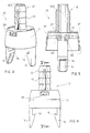
- a cap 10 is positioned at the rear above the lamp-holder 1.
- the cap 10 is made of insulating material and comprises a substantially cylindrical hollow body 11. Above the body 11 rises a hollow tubular part 12 having an entry hole 100 for the electric cable.
- the tubular part 12 has flexible serrations 13 that protrude outward to allow forced engagement inside a hole in a supporting base 14 of the lamp.
- the tubular part 12 can have an outer thread for fixing to the base of the lamp by means of a nut or metal ring.
- the tongues 15 have protrusions or small retaining teeth 16 such as to engage in corresponding seats made in the lamp-holder 1.
- Two opposite jaws 20 are provided inside the body 11 of the cap. Each jaw 20 is supported by a small bridge 21 connected to the inner wall of the body 11.
- the small bridge 21 is made of a suitable flexible material to allow elastic yielding of the jaws 20.
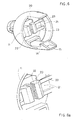
- two reinforcing ribs 23 ( Figures 6 and 7), parallel with each other, to avoid possible breakage of the small bridge.
- two slits 24 are made, in diametrically opposite positions, to allow elastic yielding of the small bridges 21 when pressure is exerted.
- the opposite surfaces of the jaws 20 have serrations 22 which are inclined slightly downward in order to be able to clasp the electric cable 6.
- the electric cable 6 is inserted through the hole 100 from the top of the tubular part 12, then passes through the jaws 20 provided inside the body 11 of the cap 10.
- the jaws 20 are in close contact with the cable 6. Downward traction of the cable 6 causes pressure on the jaws 20 and thus downward elastic yielding of the small bridges 21 that support the jaws. Since the serrations 22 of the jaws face downward, they do not oppose downward sliding of the cable 6.
- the strands 5 of the cable are inserted in the seats 4 of the contacts of the lamp-holder 1 and the cap 10 is snap fastened onto the lamp-holder through engagement of the elastic tongues 15.
Landscapes
- Arrangement Of Elements, Cooling, Sealing, Or The Like Of Lighting Devices (AREA)
- Fastening Of Light Sources Or Lamp Holders (AREA)
Applications Claiming Priority (2)
| Application Number | Priority Date | Filing Date | Title |
|---|---|---|---|
| IT2000MI000073A IT1316292B1 (it) | 2000-01-21 | 2000-01-21 | Portalampada con dispositivo di bloccaggio rapido nel cavo dialimentazione |
| ITMI200073 | 2000-01-21 |
Publications (2)
| Publication Number | Publication Date |
|---|---|
| EP1119081A1 true EP1119081A1 (de) | 2001-07-25 |
| EP1119081B1 EP1119081B1 (de) | 2008-07-23 |
Family
ID=11443738
Family Applications (1)
| Application Number | Title | Priority Date | Filing Date |
|---|---|---|---|
| EP00112489A Expired - Lifetime EP1119081B1 (de) | 2000-01-21 | 2000-06-13 | Lampenfassung mit Schnellfixieranordnung für elektrische Kabel |
Country Status (4)
| Country | Link |
|---|---|
| EP (1) | EP1119081B1 (de) |
| DE (1) | DE60039575D1 (de) |
| ES (1) | ES2332866T3 (de) |
| IT (1) | IT1316292B1 (de) |
Cited By (1)
| Publication number | Priority date | Publication date | Assignee | Title |
|---|---|---|---|---|
| CN114696173A (zh) * | 2020-12-29 | 2022-07-01 | 欧普照明股份有限公司 | 一种灯座 |
Citations (3)
| Publication number | Priority date | Publication date | Assignee | Title |
|---|---|---|---|---|
| GB1396790A (en) * | 1972-05-26 | 1975-06-04 | British Insulated Callenders | Electrical fitting incorporating cable-strain relieving means |
| DE2829639B1 (de) * | 1978-07-06 | 1979-11-29 | Subklew Christof Fa | Elektrischer Baustein |
| DE8805216U1 (de) * | 1987-04-24 | 1988-08-25 | VLM-W. Murjahn GmbH & Co., 40822 Mettmann | Glühlampenfassung |
-
2000
- 2000-01-21 IT IT2000MI000073A patent/IT1316292B1/it active
- 2000-06-13 ES ES00112489T patent/ES2332866T3/es not_active Expired - Lifetime
- 2000-06-13 DE DE60039575T patent/DE60039575D1/de not_active Expired - Fee Related
- 2000-06-13 EP EP00112489A patent/EP1119081B1/de not_active Expired - Lifetime
Patent Citations (3)
| Publication number | Priority date | Publication date | Assignee | Title |
|---|---|---|---|---|
| GB1396790A (en) * | 1972-05-26 | 1975-06-04 | British Insulated Callenders | Electrical fitting incorporating cable-strain relieving means |
| DE2829639B1 (de) * | 1978-07-06 | 1979-11-29 | Subklew Christof Fa | Elektrischer Baustein |
| DE8805216U1 (de) * | 1987-04-24 | 1988-08-25 | VLM-W. Murjahn GmbH & Co., 40822 Mettmann | Glühlampenfassung |
Cited By (1)
| Publication number | Priority date | Publication date | Assignee | Title |
|---|---|---|---|---|
| CN114696173A (zh) * | 2020-12-29 | 2022-07-01 | 欧普照明股份有限公司 | 一种灯座 |
Also Published As
| Publication number | Publication date |
|---|---|
| EP1119081B1 (de) | 2008-07-23 |
| IT1316292B1 (it) | 2003-04-10 |
| ITMI20000073A0 (it) | 2000-01-21 |
| DE60039575D1 (de) | 2008-09-04 |
| ITMI20000073A1 (it) | 2001-07-21 |
| ES2332866T3 (es) | 2010-02-15 |
Similar Documents
| Publication | Publication Date | Title |
|---|---|---|
| US7151223B2 (en) | Snap fit electrical connector assembly with outer frustro conical retainer ring and internal unidirectional snap fit wire conductor retainer | |
| US4880387A (en) | Connector for flexible electrical conduit | |
| US7154042B2 (en) | Electrical connector with snap fit retainer ring constructed to enhance the connection of the connector to an electrical box | |
| US7358448B2 (en) | Electrical connector assembly with frusto-conical snap fit retaining ring for enhancing electrical grounding of the connector assembly to an electrical box and installation tool therefor | |
| CA2120684C (en) | Easy-insertion integrally hinged c-shaped connector | |
| US6849803B1 (en) | Electrical connector | |
| US5132493A (en) | Device for connecting non-metallic sheathed cable to an electric box | |
| US6335488B1 (en) | Snap in cable connector | |
| US7057107B2 (en) | Snap fit electrical connector assembly with conical outer snap fit retainer and externally mounted internal wire retainer | |
| US20070026735A1 (en) | Button style cord connector | |
| US5411228A (en) | Cable clip | |
| US4474489A (en) | Tension-relieving cable duct | |
| US7214890B2 (en) | Electrical connector having an outlet end angularly disposed relative an inlet end with outer retainer ring about the outlet end and internal unidirectional conductor retainer in the inlet end | |
| US20060141827A1 (en) | Snap fit electrical connector assembly with operating tool for facilitating the connection of a connector assembly to an electrical box | |
| US7506993B2 (en) | Fluorescent bulb retaining spring | |
| JPS5855725B2 (ja) | 一体造りの金属クリツプ | |
| EP1119081B1 (de) | Lampenfassung mit Schnellfixieranordnung für elektrische Kabel | |
| KR100217971B1 (ko) | 제1부재를 제2부재상의 소정의 위치에 보유시키는 고정장치 | |
| US20080296061A1 (en) | Connector for an electrical junction box | |
| GB2028411A (en) | A Clamp for Mounting a Housing on a Bar | |
| JP2000034810A (ja) | 竪樋取付け構成体 | |
| CN218565226U (zh) | 一种快装吸顶灯 | |
| GR3035598T3 (en) | Cable clamp | |
| JPH0653659U (ja) | カランの取付構造 | |
| US4294503A (en) | Locking means for a lamp holder |
Legal Events
| Date | Code | Title | Description |
|---|---|---|---|
| PUAI | Public reference made under article 153(3) epc to a published international application that has entered the european phase |
Free format text: ORIGINAL CODE: 0009012 |
|
| AK | Designated contracting states |
Kind code of ref document: A1 Designated state(s): DE ES SE |
|
| AX | Request for extension of the european patent |
Free format text: AL;LT;LV;MK;RO;SI |
|
| 17P | Request for examination filed |
Effective date: 20011116 |
|
| AKX | Designation fees paid |
Free format text: DE ES SE |
|
| 17Q | First examination report despatched |
Effective date: 20061027 |
|
| GRAP | Despatch of communication of intention to grant a patent |
Free format text: ORIGINAL CODE: EPIDOSNIGR1 |
|
| GRAS | Grant fee paid |
Free format text: ORIGINAL CODE: EPIDOSNIGR3 |
|
| GRAA | (expected) grant |
Free format text: ORIGINAL CODE: 0009210 |
|
| AK | Designated contracting states |
Kind code of ref document: B1 Designated state(s): DE ES SE |
|
| REF | Corresponds to: |
Ref document number: 60039575 Country of ref document: DE Date of ref document: 20080904 Kind code of ref document: P |
|
| REG | Reference to a national code |
Ref country code: SE Ref legal event code: TRGR |
|
| PLBE | No opposition filed within time limit |
Free format text: ORIGINAL CODE: 0009261 |
|
| STAA | Information on the status of an ep patent application or granted ep patent |
Free format text: STATUS: NO OPPOSITION FILED WITHIN TIME LIMIT |
|
| 26N | No opposition filed |
Effective date: 20090424 |
|
| REG | Reference to a national code |
Ref country code: ES Ref legal event code: FG2A Ref document number: 2332866 Country of ref document: ES Kind code of ref document: T3 |
|
| PG25 | Lapsed in a contracting state [announced via postgrant information from national office to epo] |
Ref country code: DE Free format text: LAPSE BECAUSE OF NON-PAYMENT OF DUE FEES Effective date: 20100101 |
|
| REG | Reference to a national code |
Ref country code: ES Ref legal event code: FD2A Effective date: 20090615 |
|
| PG25 | Lapsed in a contracting state [announced via postgrant information from national office to epo] |
Ref country code: ES Free format text: LAPSE BECAUSE OF NON-PAYMENT OF DUE FEES Effective date: 20090615 |
|
| PGFP | Annual fee paid to national office [announced via postgrant information from national office to epo] |
Ref country code: SE Payment date: 20110622 Year of fee payment: 12 |
|
| REG | Reference to a national code |
Ref country code: SE Ref legal event code: EUG |
|
| PG25 | Lapsed in a contracting state [announced via postgrant information from national office to epo] |
Ref country code: SE Free format text: LAPSE BECAUSE OF NON-PAYMENT OF DUE FEES Effective date: 20120614 |