EP1118580A1 - Device for automatic tension control of a cable for a piste grooming device - Google Patents
Device for automatic tension control of a cable for a piste grooming device Download PDFInfo
- Publication number
- EP1118580A1 EP1118580A1 EP01200199A EP01200199A EP1118580A1 EP 1118580 A1 EP1118580 A1 EP 1118580A1 EP 01200199 A EP01200199 A EP 01200199A EP 01200199 A EP01200199 A EP 01200199A EP 1118580 A1 EP1118580 A1 EP 1118580A1
- Authority
- EP
- European Patent Office
- Prior art keywords
- setpoint
- rope
- winch
- control unit
- sensor elements
- Prior art date
- Legal status (The legal status is an assumption and is not a legal conclusion. Google has not performed a legal analysis and makes no representation as to the accuracy of the status listed.)
- Granted
Links
Images


Classifications
-
- B—PERFORMING OPERATIONS; TRANSPORTING
- B66—HOISTING; LIFTING; HAULING
- B66D—CAPSTANS; WINCHES; TACKLES, e.g. PULLEY BLOCKS; HOISTS
- B66D1/00—Rope, cable, or chain winding mechanisms; Capstans
- B66D1/28—Other constructional details
- B66D1/40—Control devices
- B66D1/48—Control devices automatic
- B66D1/50—Control devices automatic for maintaining predetermined rope, cable, or chain tension, e.g. in ropes or cables for towing craft, in chains for anchors; Warping or mooring winch-cable tension control
- B66D1/505—Control devices automatic for maintaining predetermined rope, cable, or chain tension, e.g. in ropes or cables for towing craft, in chains for anchors; Warping or mooring winch-cable tension control electrical
Landscapes
- Engineering & Computer Science (AREA)
- Mechanical Engineering (AREA)
- Road Paving Machines (AREA)
- Carriers, Traveling Bodies, And Overhead Traveling Cranes (AREA)
- Lifting Devices For Agricultural Implements (AREA)
- Operation Control Of Excavators (AREA)
- Earth Drilling (AREA)
- Control And Safety Of Cranes (AREA)
- Load-Engaging Elements For Cranes (AREA)
- Lift-Guide Devices, And Elevator Ropes And Cables (AREA)
Abstract
Description
Die vorliegende Erfindung bezieht sich auf eine Einrichtung zur automatischen Einstellung und Regelung der Zugkraft des Seiles einer Überkopfseilwinde für ein Pistenpflegegerät gemäß dem Oberbegriff des Anspruchs 1.The present invention relates to a Automatic adjustment device and Regulation of the tensile force of the rope of an overhead winch for a slope grooming device according to the preamble of claim 1.
Zum Einhalten einer vorgegebenen Seilzugkraft sind Regeleinrichtungen für Seilwinden bekannt, um einen steuerbaren Windenantrieb derart zu beeinflussen, dass ein Überschreiten und Unterschreiten der eingestellten Zugkräfte vermieden werden. Eine erhöhte Seilbelastung kann zum Seilriss mit schwerwiegenden Folgen führen. Außerdem berücksichtigen Regeleinrichtungen der bekannten Art nicht die Dynamik eines Fahrzeuges an dem sie angebracht sind, insbesondere nicht die verschiedenen Winkelpositionen, die das Seil gegenüber dem Fahrzeug einnehmen kann. Dadurch dass die Regeleinrichtungen der Seilkraft bei bekannten Seilwinden nur in Abhängigkeit des Sollwertes der zulässigen Seilspannung einstellbar sind, wird nicht den Fahrgegebenheiten des Fahrzeuges Rechnung getragen und das Seil unterliegt Zugkräften, die durch die Ausführung von bestimmten Arbeiten in ihrer Größe nicht notwendig sind. Dies verringert unnütziger Weise die Seillebensdauer. To maintain a specified rope pulling force control devices for winches are known, to such a controllable winch drive influence that an exceeding and falling below of the set tractive forces avoided become. An increased rope load can lead to Lead rope break with serious consequences. Moreover take into account control devices of the known type not the dynamics of a vehicle to which they are attached, in particular not the different angular positions that the rope can take up opposite the vehicle. Because of the control devices of the rope force with known winches only dependent the nominal value of the permissible rope tension are adjustable, is not the driving conditions of the vehicle and that Rope is subject to tensile forces caused by the execution of certain works in their size are not necessary. This reduces uselessness Way the rope life.
Die Aufgabe der vorliegenden Erfindung liegt daher darin, die Nachteile der bekannten Regeleinrichtungen zu beseitigen und eine Einrichtung zur automatischen Verstellung der Zugkraft vorzuschlagen, den Gegebenheiten eines Pistenpflegegerätes Rechnung zu tragen, mit dem Ziel, die erforderliche Zugkraft jederzeit zur Verfügung zu stellen, sie aber gleichzeitig auf das gerade erforderliche Maß zu beschränken. Überdies soll eine Sollwertvorgabe für die Zugkraft selbsttätig erfolgen.The object of the present invention is therefore in it the disadvantages of the known control devices eliminate and set up for automatic adjustment of the pulling force propose the circumstances of a Piste grooming device to take into account with the Aim to provide the required traction at all times To make them available, but at the same time to limit the measure just required. In addition, a target value for the pulling force should be given done automatically.
Diese Aufgabe wird erfindungsgemäß durch eine Einrichtung zur automatischen Regelung der Zugkraft einer Überkopfseilwinde für ein Pistenpflegegerät gelöst, in der die Merkmale des kennzeichnenden Teils des Anspruchs 1 vorgesehen werden.This object is achieved by a Automatic traction control device an overhead winch for a piste grooming device solved in which the characteristics of the characterizing part of claim 1 provided become.
Mit Hilfe einer Steuer- und Regeleinheit und dort hinterlegten Algorithmus aus verschiedenen mit Sensoren gewonnenen Messwerten wird ein Sollwert für die Zugkraft ermittelt. Der Sollwert wird in Abhängigkeit vom Druck im hydrostatischen Fahrantrieb und vom Winkel des Seils relativ zum Fahrzeug sowie eines vom Fahrer vorgegebenen Korrekturwertes gebildet. In einem nachgeschalteten geschlossenen Regelkreis wird der so gewonnene Sollwert mit dem mittels eines Kraftmessbolzens gemessene Istwert verglichen und die Zugkraft auf den Sollwert geregelt. With the help of a control and regulation unit and there algorithm from different Measured values obtained with sensors become a Target value for the tensile force determined. The setpoint is dependent on the pressure in the hydrostatic Travel drive and the angle of the rope relative to the vehicle and one from the driver predetermined correction value formed. In one downstream closed loop the setpoint obtained in this way by means of a Force measuring bolt measured actual value compared and the traction is regulated to the setpoint.
Als Maß für die erforderliche Zugkraft bietet sich der Druck im Fahrantrieb an. Wenn sich das Windenseil z.B. in Fahrtrichtung vorn befindet und ein hoher Druck auf der Vorwärtsseite des Fahrantriebes liegt, so sollte auch die Windenzugkraft entsprechend höher gewählt werden. Liegt der Druck jedoch auf der "Rückwärtsseite" an, mit dem Windenseil in Fahrtrichtung vorne, so bedeutet dies, dass die Überkopfseilwinde gegen den Fahrantrieb arbeitet. In diesem Fall sollte die Windenzugkraft möglichst gering eingestellt werden.As a measure of the required pulling force the pressure in the traction drive. If that Winch rope e.g. in the direction of travel and a high pressure on the forward side of the Traction drive, so should the winch traction be chosen accordingly higher. However, if the pressure is on the "reverse side" with the winch rope in the direction of travel at the front, so this means that the overhead winch works against the travel drive. In this case the winch pull should be set as low as possible become.
Weiterhin soll die Windenzugkraft reduziert werden, wenn sie quer zur Fahrtrichtung angreift. Für den Fall, dass die Steuer- und Regeleinheit aufgrund ungünstiger Schneeverhältnisse (z.B. Neuschnee) falsche Zugkraftsollwerte liefert, hat der Fahrer die Möglichkeit zum Übersteuern, u.zw. eine Steigerung oder Reduktion der Zugkraft zu ermöglichen.Furthermore, the winch pulling force should be reduced if it attacks transversely to the direction of travel. In the event that the control and regulating unit due to unfavorable snow conditions (e.g. fresh snow) incorrect tractive force setpoints delivers, the driver has the opportunity to Oversteer, etc. an increase or decrease to allow the tractive force.
Weitere Merkmale und Vorteile der erfindungsgemäßen Einrichtung gehen aus den Ansprüchen und aus der folgenden Beschreibung einer bevorzugten Ausführungsform unter Bezugnahme auf die beigefügte Zeichnung hervor. Es zeigen,
- Figur 1
- ein Schaubild der erfindungsgemäßen Einrichtung angewandt auf ein Pistenpflegegerät bekannter Art,
- Figur 2
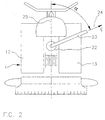
- schematisch ein Pistenpflegegerät mit Überkopfseile,
- Figur 3
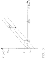
- ein Diagramm zur Bestimmung eines Zugkraftwertes,
Figur 4- ein Diagramm zur Bestimmung der maximal zulässigen Zugkraft, und
- Figur 5
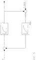
- schematisch einen Regelkreis zum Vergleich eines Istwertes der Zugkraft und Regelung des Istwertes auf den Sollwert.
- Figure 1
- 2 shows a diagram of the device according to the invention applied to a piste grooming device of a known type,
- Figure 2
- schematically a piste grooming device with overhead ropes,
- Figure 3
- a diagram for determining a tensile force value,
- Figure 4
- a diagram for determining the maximum permissible tractive force, and
- Figure 5
- schematically a control loop for comparing an actual value of the tractive force and regulating the actual value to the setpoint.
In Figur 1 ist schematisch ein Bild mit der Bezugsziffer
1 im allgemein bezeichnetes Pistenpflegegerät
bekannter Art angegeben. Es umfasst
beispielsweise einen Dieselmotor 2, der über
ein Getriebe 3 eine erste Pumpe 4 und eine
zweite Pumpe 5 antreibt. Die hydraulische Pumpe
4 versorgt über eine Förderleitung 6 einen Hydromotor
7, bzw. die Pumpe 5 versorgt über eine
Förderleitung 8 einen Hydromotor 9 mit Druckmittel.
Der Hydromotor 7 ist über eine Rückführleitung
10 und der Hydromotor 9 über eine
Rückführleitung 11 mit der Pumpe 4 bzw. 5 verbunden.
Der Hydromotor 7 treibt eine, in Fahrtrichtung
gesehen rechte Raupenkette 12 und der
Hydromotor 9 eine linke Raupenkette 13 an. Die
bis jetzt beschriebenen Teile eines Pistenpflegegerätes
sind bekannter Art und dienen nur zur
besseren Verständlichkeit der nachfolgenden Beschreibung
der erfindungsgemäßen Einrichtung. In Figure 1 is a diagram with the reference number schematically
1 generally designated piste grooming device
known type specified. It includes
for example, a diesel engine 2, the
a transmission 3, a
Die Förderleitung 6 ist über eine Abzweigung 14
und die Förderleitung 8 über eine Abzweigung 15
mit einem Wechselventil 16 verbunden, das fähig
ist, den höheren der beiden in den Leitungen 6
und 8 anstehenden Drücke über eine Leitung 17
von einem Drucksensor A erfassen zu lassen.The delivery line 6 is via a
Auf ähnliche Weise ist die Rückleitung 10 über
eine Abzweigung 18 und die Rückleitung 8 über
eine Abzweigung 19 mit einem Wechselventil 20
verbunden, das über eine Leitung 21 mit einem
Drucksensor B verbunden ist.Similarly,
Somit werden für die Messung des Druckes im
Fahrantrieb die beiden Drucksensoren A und B
verwendet. Der Sensor A ist somit über das
Wechselventil 16 mit den "Vorwärtsseiten", der
zweite Sensor B über das Wechselventil 20 mit
den "Rückwärtsseiten" der beiden hydrostatischen
Fahrantriebe in der Form der Hydromotore
7 und 9 verbunden. Dadurch steht an den beiden
Sensoren A und B der jeweils höhere Druck der
"Vorwärtsseite" bzw. "Rückwärtsseite" des rechten
und des linken Fahrantriebes an.Thus, for the measurement of the pressure in the
Travel drive the two pressure sensors A and B.
used. Sensor A is thus over the
In Figur 2 ist schematisch das Pistenpflegegerät
aus Figur 1 von oben dargestellt. Eine Überseilwinde
ist in 22 symbolisiert. Sie besitzt
einen Windenausleger 23, der das Windenseil
24 innerhalb eines Winkels α gegenüber der
Fahrtrichtung 25 des Pistenpflegegerätes 1
führt. The piste grooming device is shown schematically in FIG
shown in Figure 1 from above. A cable winch
is symbolized in 22. she owns
a
Der Winkel α des Seils 24 bzw. des Windenauslegers
23 bezüglich der Fahrzeuglenkachse bzw.
der Fahrtrichtung 25 wird mit Hilfe eines nicht
dargestellten Drehwinkelgeber bekannter Art bestimmt,
der ein zum Winkel α proportionales
Spannungssignal liefert. Befindet sich der Windenausleger
23 in Fahrtrichtung vorn, so entspricht
dies α = 0°, befindet er sich in Fahrtrichtung
hinten, entspricht dies einem Winkel
von α = 180°. Das Winkelsignal ist für positive
und negative Winkel gleich (z.B. liefert ein
Winkel von α = 60° das gleiche Signal wie ein
Winkel von α = -60° bzw. α = 300°), da eine Unterscheidung
zwischen rechter und linker Seite
für die Ermittlung der Zugkraft von keiner Bedeutung
ist.The angle α of the
Über ein nicht dargestelltes Potentiometer kann ein Korrekturwert vom Fahrer eingestellt werden. Die Steuer- und Regeleinheit für die Windenzugkraft, die im Normalbetrieb vollautomatisch arbeitet, kann durch Einstellen eines Korrekturwertes vom Fahrer gesteuert werden. Das dafür eingesetzte Potentiometer kann aus einer federbelasteten Mittelstellung heraus in positive und negative Richtung ausgelenkt werden. Dadurch ist es möglich, den von der Steuer- und Regeleinrichtung automatisch ermittelten Zugkraftsollwert je nach Bedarf zu verringern oder zu erhöhen. Nach Loslassen des Potentiometers kehrt dies automatisch in die Mittelstellung zurück, so dass der Korrekturwert 0 ist und der Zugkraftsollwert nunmehr wieder vollautomatisch ermittelt wird.Via a potentiometer, not shown a correction value can be set by the driver. The control unit for the winch traction, the fully automatic in normal operation works by setting a Correction value can be controlled by the driver. The potentiometer used for this can be switched off a spring-loaded middle position in positive and negative direction are deflected. This makes it possible to and control device automatically determined Reduce the pulling force setpoint as required or increase. After releasing the potentiometer this automatically returns to the middle position back so that the correction value is 0 and the tractive force setpoint is now again is determined fully automatically.
Die Ermittlung des Zugkraftsollwertes in der
Steuer- und Regeleinrichtung erfolgt in zwei
Schritten:
Wie in Figur 3 gezeigt, wird abhängig vom Druck
p im Fahrantrieb und vom Korrekturwert K1 der
vom Fahrer über das Potentiometer einstellbar
ist, der Zugkraftwert F* wie folgt unter Bezugnahme
auf Figur 3 bestimmt:
As shown in FIG. 3, the tensile force value F * is determined as follows, with reference to FIG. 3, as a function of the pressure p in the traction drive and the correction value K 1 that can be set by the driver via the potentiometer:
In einem zweiten Schritt wird gemäß der Figur 4 je nach Winkel α des Windenauslegers und Anliegen der Drücke PA und PB die maximal zulässige Kraft Fzul bestimmt , wobei das obere Diagramm der Figur 4 für Druck auf der "Vorwärtsseite" ausgelegt ist und das untere Diagramm für Druck auf der "Rückwärtsseite".In a second step, according to FIG. 4, depending on the angle α of the winch arm and the application of pressures P A and P B, the maximum permissible force F perm is determined, the upper diagram in FIG. 4 being designed for pressure on the "forward side" and that lower diagram for pressure on the "reverse side".
Der geringere der beiden Werte F* und Fzul stellt den Zugkraftsollwert Fsoll dar. The lower of the two values F * and F represents the permissible tensile force setpoint F is intended.
In einem geschlossenen Regelkreis wird dieser Wert mit dem mittels eines Kraftmessbolzens gemessenen Istwert der Zugkraft Fist verglichen und der Istwert wird auf den Sollwert geregelt.In a closed control loop, this value is compared with the actual value of the tensile force F ist measured by means of a force measuring bolt and the actual value is regulated to the target value.
Claims (5)
Applications Claiming Priority (2)
| Application Number | Priority Date | Filing Date | Title |
|---|---|---|---|
| IT2000BZ000005A IT1316116B1 (en) | 2000-01-21 | 2000-01-21 | DEVICE FOR THE AUTOMATIC SETTING AND ADJUSTMENT OF THE FORZADI TRACTION OF A ROPE OF A WINCH OVERHEAD FOR A MACHINE |
| ITBZ200005 | 2000-01-21 |
Publications (2)
| Publication Number | Publication Date |
|---|---|
| EP1118580A1 true EP1118580A1 (en) | 2001-07-25 |
| EP1118580B1 EP1118580B1 (en) | 2004-09-22 |
Family
ID=11440841
Family Applications (1)
| Application Number | Title | Priority Date | Filing Date |
|---|---|---|---|
| EP01200199A Expired - Lifetime EP1118580B1 (en) | 2000-01-21 | 2001-01-19 | Device for automatic tension control of a cable for a piste grooming device |
Country Status (6)
| Country | Link |
|---|---|
| US (1) | US6585232B2 (en) |
| EP (1) | EP1118580B1 (en) |
| JP (1) | JP4780837B2 (en) |
| AT (1) | ATE276966T1 (en) |
| DE (1) | DE50103695D1 (en) |
| IT (1) | IT1316116B1 (en) |
Cited By (6)
| Publication number | Priority date | Publication date | Assignee | Title |
|---|---|---|---|---|
| EP1431236A2 (en) * | 2002-12-17 | 2004-06-23 | Kässbohrer Geländefahrzeug AG | Method for controlling the winch of a ski track maintenance vehicle and said vehicle |
| DE102010049984A1 (en) * | 2010-10-19 | 2012-04-19 | Kässbohrer Geländefahrzeug AG | Method for controlling a winch of a tracked vehicle and snowcat |
| CN102491173A (en) * | 2011-12-12 | 2012-06-13 | 中联重科股份有限公司 | Crane and closed type winch negative power control system for crane |
| IT201700064293A1 (en) * | 2017-06-09 | 2018-12-09 | Prinoth Spa | ASSISTANT WINCH GROUP FOR THE MOVEMENT OF A TRACKED VEHICLE AND ITS CONTROL METHOD |
| IT202100032639A1 (en) | 2021-12-24 | 2023-06-24 | Prinoth Spa | WINCH ASSEMBLY TO AID THE MOVEMENT OF A TRACKED VEHICLE AND RELATED CONTROL METHOD |
| EP4242162A1 (en) | 2022-03-10 | 2023-09-13 | Kässbohrer Geländefahrzeug AG | Method for controlling a winch assembly of a piste caterpillar, device for carrying out said method and piste caterpillar |
Families Citing this family (17)
| Publication number | Priority date | Publication date | Assignee | Title |
|---|---|---|---|---|
| ITBZ20030005A1 (en) * | 2003-01-30 | 2004-07-31 | High Technology Invest Bv | PRESSER DEVICE FOR CONDUCTING ROPE IN ROPE TRACTION TRANSPORT SYSTEMS. |
| DE102005031076B4 (en) * | 2005-06-27 | 2007-11-29 | Kässbohrer Geländefahrzeug AG | Piste care vehicle with cable torque compensation |
| ITBZ20050051A1 (en) * | 2005-09-29 | 2007-03-30 | High Technology Invest Bv | ANTI-SCROLL-UP DEVICE FOR FUNPOSAL SYSTEM ROPES. |
| ITMI20070835A1 (en) * | 2007-04-20 | 2008-10-21 | Rolic Invest Sarl | ROPE TRANSPORTATION SYSTEM AND METHOD OF OPERATION OF THE SAME |
| ITMI20070157U1 (en) * | 2007-04-20 | 2008-10-21 | Rolic Invest Sarl | CHAIRLIFT |
| ITMI20071618A1 (en) | 2007-08-03 | 2009-02-04 | Rolic Invest Sarl | ROPE TRANSPORTATION SYSTEM AND METHOD OF OPERATION OF THE SAME |
| ITMI20072071A1 (en) * | 2007-10-26 | 2009-04-27 | Rolic Invest Sarl | ROPE TRANSPORTATION SYSTEM AND METHOD OF OPERATION OF THE SAME |
| EP2075172A1 (en) * | 2007-12-28 | 2009-07-01 | Rolic Invest Sarl | Cableway system with supporting cables and a separate haulage cable |
| MX2011003461A (en) * | 2008-10-03 | 2011-05-19 | Schlumberger Technology Bv | Configurable hydraulic system. |
| IT1395098B1 (en) | 2009-07-09 | 2012-09-05 | Rolic Invest Sarl | TRANSPORT UNIT FOR ROPE TRANSPORT SYSTEMS |
| IT1395737B1 (en) | 2009-08-04 | 2012-10-19 | Rolic Invest Sarl | RECALL OF A SEAT FOR SKILIFT |
| US8613426B1 (en) | 2009-12-14 | 2013-12-24 | L.E. Myers Co. | Power line puller control package |
| IT1401120B1 (en) | 2010-07-14 | 2013-07-12 | Rolic Invest Sarl | EXCHANGE FOR ROPE TRANSPORTATION SYSTEM AND ROPE TRANSPORTATION SYSTEM INCLUDING SUCH EXCHANGE. |
| CN102424330B (en) * | 2011-08-19 | 2013-12-18 | 三一汽车起重机械有限公司 | Crane and hook take-up system and method thereof |
| EP3067309B1 (en) | 2015-03-10 | 2019-08-07 | HAWE Hydraulik SE | Control valve for a hydraulic unit and hydraulic system with a corresponding control valve |
| US10633230B2 (en) * | 2018-04-10 | 2020-04-28 | Goodrich Corporation | Integrated hoist maintenance and method of hoist operation |
| IT202200003908A1 (en) * | 2022-03-02 | 2023-09-02 | Prinoth Spa | TRACKED VEHICLE FOR THE PREPARATION OF SKI SLOPES AND METHOD OF DRIVING THE TRACKED VEHICLE |
Citations (3)
| Publication number | Priority date | Publication date | Assignee | Title |
|---|---|---|---|---|
| US4108264A (en) * | 1975-12-29 | 1978-08-22 | Kabushiki Kaisha Komatsu Seisakusho | Cable take-up device for electric drive vehicle |
| EP0761890A1 (en) * | 1995-09-07 | 1997-03-12 | MDP Meccanica del Piave S.p.A. | Safety device for the manoeuvring and auxiliary winching of self-propelled vehicles used on steep slopes |
| DE19647169A1 (en) * | 1996-11-13 | 1998-05-28 | Samsung Heavy Ind | Control device for driving system in construction vehicles |
Family Cites Families (10)
| Publication number | Priority date | Publication date | Assignee | Title |
|---|---|---|---|---|
| US3032321A (en) * | 1960-01-29 | 1962-05-01 | Plumettaz Sa | Control devices for powered winches |
| US3940110A (en) * | 1974-04-12 | 1976-02-24 | Kenro Motoda | Lifting apparatus |
| GB1589769A (en) * | 1976-12-14 | 1981-05-20 | Secretary Industry Brit | System for controlling the position of a tethered floating vessel |
| US4187681A (en) * | 1978-08-28 | 1980-02-12 | Bucyrus-Erie Company | Hydrostatic winch |
| US4448398A (en) * | 1982-03-01 | 1984-05-15 | Garlock Equipment Company | Winch control system |
| JPH063850Y2 (en) * | 1990-06-25 | 1994-02-02 | 株式会社トーメン | Slope maintenance equipment |
| JPH07113564A (en) * | 1993-10-18 | 1995-05-02 | Seirei Ind Co Ltd | Self-traveling ice scattering apparatus |
| JP3305834B2 (en) * | 1993-10-18 | 2002-07-24 | セイレイ工業株式会社 | Hydraulic circuit of self-propelled ice spreader |
| JP3508662B2 (en) * | 1998-12-25 | 2004-03-22 | コベルコ建機株式会社 | Hydraulic drive winch control method and device |
| US6382595B1 (en) * | 2000-07-26 | 2002-05-07 | Schlumberger Technology Corporation | Differential hydrostatic transmission system |
-
2000
- 2000-01-21 IT IT2000BZ000005A patent/IT1316116B1/en active
-
2001
- 2001-01-17 US US09/766,459 patent/US6585232B2/en not_active Expired - Lifetime
- 2001-01-19 DE DE50103695T patent/DE50103695D1/en not_active Expired - Fee Related
- 2001-01-19 JP JP2001011350A patent/JP4780837B2/en not_active Expired - Lifetime
- 2001-01-19 EP EP01200199A patent/EP1118580B1/en not_active Expired - Lifetime
- 2001-01-19 AT AT01200199T patent/ATE276966T1/en active
Patent Citations (3)
| Publication number | Priority date | Publication date | Assignee | Title |
|---|---|---|---|---|
| US4108264A (en) * | 1975-12-29 | 1978-08-22 | Kabushiki Kaisha Komatsu Seisakusho | Cable take-up device for electric drive vehicle |
| EP0761890A1 (en) * | 1995-09-07 | 1997-03-12 | MDP Meccanica del Piave S.p.A. | Safety device for the manoeuvring and auxiliary winching of self-propelled vehicles used on steep slopes |
| DE19647169A1 (en) * | 1996-11-13 | 1998-05-28 | Samsung Heavy Ind | Control device for driving system in construction vehicles |
Cited By (18)
| Publication number | Priority date | Publication date | Assignee | Title |
|---|---|---|---|---|
| EP1431236A2 (en) * | 2002-12-17 | 2004-06-23 | Kässbohrer Geländefahrzeug AG | Method for controlling the winch of a ski track maintenance vehicle and said vehicle |
| DE10261944A1 (en) * | 2002-12-17 | 2004-07-01 | Kässbohrer Geländefahrzeug AG | Method for controlling a winch of a piste grooming vehicle and piste grooming vehicle |
| EP1431236A3 (en) * | 2002-12-17 | 2005-04-27 | Kässbohrer Geländefahrzeug AG | Method for controlling the winch of a ski track maintenance vehicle and said vehicle |
| US7165758B2 (en) | 2002-12-17 | 2007-01-23 | Kaessbohrer Gelaendefahrzeug Ag | Snow-trail grooming vehicle having a cable winch thereon and a method for controlling the cable winch |
| DE102010049984A1 (en) * | 2010-10-19 | 2012-04-19 | Kässbohrer Geländefahrzeug AG | Method for controlling a winch of a tracked vehicle and snowcat |
| EP2444356A1 (en) * | 2010-10-19 | 2012-04-25 | Kässbohrer Geländefahrzeug AG | Method for operating a winch of a tracked vehicle and snow groomer |
| CN102491173A (en) * | 2011-12-12 | 2012-06-13 | 中联重科股份有限公司 | Crane and closed type winch negative power control system for crane |
| CN102491173B (en) * | 2011-12-12 | 2014-04-02 | 中联重科股份有限公司 | Crane and closed type winch negative power control system for crane |
| IT201700064293A1 (en) * | 2017-06-09 | 2018-12-09 | Prinoth Spa | ASSISTANT WINCH GROUP FOR THE MOVEMENT OF A TRACKED VEHICLE AND ITS CONTROL METHOD |
| WO2018225031A1 (en) * | 2017-06-09 | 2018-12-13 | Prinoth S.P.A. | Winch assembly for assisting the movement of a tracked vehicle and control method thereof |
| CN109019379A (en) * | 2017-06-09 | 2018-12-18 | 普瑞诺斯股份公司 | The winch component and its control method and caterpillar of caterpillar |
| CN109019379B (en) * | 2017-06-09 | 2021-05-25 | 普瑞诺斯股份公司 | Winch assembly of crawler-type vehicle, control method of winch assembly and crawler-type vehicle |
| RU2771072C2 (en) * | 2017-06-09 | 2022-04-26 | ПРИНОТ С.п.А. | Winch assembly for assistance in movement of tracked vehicle and method for controlling it |
| US11753283B2 (en) | 2017-06-09 | 2023-09-12 | Prinoth S.P.A. | Winch assembly for assisting the movement of a tracked vehicle and control method thereof |
| IT202100032639A1 (en) | 2021-12-24 | 2023-06-24 | Prinoth Spa | WINCH ASSEMBLY TO AID THE MOVEMENT OF A TRACKED VEHICLE AND RELATED CONTROL METHOD |
| EP4201867A1 (en) | 2021-12-24 | 2023-06-28 | PRINOTH S.p.A. | Winch assembly for assisting the movement of a tracked vehicle and relative control method |
| EP4242162A1 (en) | 2022-03-10 | 2023-09-13 | Kässbohrer Geländefahrzeug AG | Method for controlling a winch assembly of a piste caterpillar, device for carrying out said method and piste caterpillar |
| DE102022202414A1 (en) | 2022-03-10 | 2023-09-14 | Kässbohrer Geländefahrzeug Aktiengesellschaft | Method for controlling a winch arrangement of a snow groomer, device for carrying out the method and snow groomer |
Also Published As
| Publication number | Publication date |
|---|---|
| DE50103695D1 (en) | 2004-10-28 |
| ATE276966T1 (en) | 2004-10-15 |
| US20010017366A1 (en) | 2001-08-30 |
| EP1118580B1 (en) | 2004-09-22 |
| ITBZ20000005A1 (en) | 2001-07-21 |
| IT1316116B1 (en) | 2003-03-28 |
| JP4780837B2 (en) | 2011-09-28 |
| JP2001248125A (en) | 2001-09-14 |
| US6585232B2 (en) | 2003-07-01 |
Similar Documents
| Publication | Publication Date | Title |
|---|---|---|
| EP1118580B1 (en) | Device for automatic tension control of a cable for a piste grooming device | |
| EP1818245B1 (en) | Trailer and method of driving a trailer | |
| DE10145588A1 (en) | Method and device for controlling a clutch | |
| DE3317091A1 (en) | TORQUE CONTROL SYSTEM WITH SPEED LIMITATION AND CONTROL METHOD FOR A HYDROSTATIC AUXILIARY DRIVE | |
| EP2377999B1 (en) | Front drive of a road finisher and method for controlling same | |
| DE202013012756U1 (en) | Stabilization of a forestry unit | |
| EP1826420B1 (en) | Method and apparatus for controlling a drive system | |
| DE60112716T2 (en) | METHOD AND DEVICE FOR REGULATING THE DRIVE SLIP FOR A VEHICLE WITH HYDRAULIC DRIVE | |
| DE10219270C1 (en) | Agricultural tractor with drive slip regulation using central microprocessor box coupled to slip and minimal velocity setting regulators and mode switch for primary control of velocity dependent on slip | |
| EP1431236B1 (en) | Method for controlling the winch of a ski track maintenance vehicle and said vehicle | |
| EP3427560B1 (en) | Towing device | |
| EP2444356B1 (en) | Method for operating a winch of a tracked vehicle and snow groomer | |
| DE202020107297U1 (en) | Control system for a hydrostatic drive | |
| DE60315779T2 (en) | vehicle steering | |
| DE3126184A1 (en) | ARRANGEMENT FOR LIMITING UN CONTROLLED BENDING MOVEMENTS IN THE JOINT BETWEEN VEHICLE UNITS OF ARTICULATED VEHICLES, IN PARTICULAR JOINT COMBUSES | |
| DE3321443A1 (en) | VIBRATION ROLLER WITH POWER LIMITATION DEVICE | |
| DE102011116528A1 (en) | Method for rotational torque control of hydrostatic drive unit of e.g. municipal vehicle, involves determining actual torque from absorption volume of hydraulic motor and pressure in closed circuits, and changing absorption volume | |
| WO2010133285A1 (en) | Arrangement for controlling the stroke of a stroking tool of a vehicle and method for controlling stroke | |
| EP3067309B1 (en) | Control valve for a hydraulic unit and hydraulic system with a corresponding control valve | |
| WO2011057688A1 (en) | Calibration method and hydraulic drive system | |
| DE10006407C2 (en) | Hydrostatic drive for a winch | |
| EP4242162A1 (en) | Method for controlling a winch assembly of a piste caterpillar, device for carrying out said method and piste caterpillar | |
| EP4384733A1 (en) | Method for starting up in a hydrostatic drive with brake | |
| WO2023016722A1 (en) | Tracked vehicle having a track tensioner | |
| DE102023202657A1 (en) | METHOD OF CONTROLLING A HYDROSTATIC DRIVE |
Legal Events
| Date | Code | Title | Description |
|---|---|---|---|
| PUAI | Public reference made under article 153(3) epc to a published international application that has entered the european phase |
Free format text: ORIGINAL CODE: 0009012 |
|
| AK | Designated contracting states |
Kind code of ref document: A1 Designated state(s): AT CH DE FR IT LI |
|
| AX | Request for extension of the european patent |
Free format text: AL;LT;LV;MK;RO;SI |
|
| 17P | Request for examination filed |
Effective date: 20011019 |
|
| AKX | Designation fees paid |
Free format text: AT CH DE FR IT LI |
|
| GRAP | Despatch of communication of intention to grant a patent |
Free format text: ORIGINAL CODE: EPIDOSNIGR1 |
|
| GRAS | Grant fee paid |
Free format text: ORIGINAL CODE: EPIDOSNIGR3 |
|
| GRAA | (expected) grant |
Free format text: ORIGINAL CODE: 0009210 |
|
| AK | Designated contracting states |
Kind code of ref document: B1 Designated state(s): AT CH DE FR IT LI |
|
| REG | Reference to a national code |
Ref country code: CH Ref legal event code: EP |
|
| REF | Corresponds to: |
Ref document number: 50103695 Country of ref document: DE Date of ref document: 20041028 Kind code of ref document: P |
|
| REG | Reference to a national code |
Ref country code: CH Ref legal event code: NV Representative=s name: KELLER & PARTNER PATENTANWAELTE AG |
|
| PLBE | No opposition filed within time limit |
Free format text: ORIGINAL CODE: 0009261 |
|
| STAA | Information on the status of an ep patent application or granted ep patent |
Free format text: STATUS: NO OPPOSITION FILED WITHIN TIME LIMIT |
|
| PG25 | Lapsed in a contracting state [announced via postgrant information from national office to epo] |
Ref country code: DE Free format text: LAPSE BECAUSE OF NON-PAYMENT OF DUE FEES Effective date: 20050802 |
|
| ET | Fr: translation filed | ||
| 26N | No opposition filed |
Effective date: 20050623 |
|
| REG | Reference to a national code |
Ref country code: CH Ref legal event code: PCAR Free format text: NEW ADDRESS: EIGERSTRASSE 2 POSTFACH, 3000 BERN 14 (CH) |
|
| REG | Reference to a national code |
Ref country code: FR Ref legal event code: PLFP Year of fee payment: 16 |
|
| REG | Reference to a national code |
Ref country code: FR Ref legal event code: PLFP Year of fee payment: 17 |
|
| REG | Reference to a national code |
Ref country code: FR Ref legal event code: PLFP Year of fee payment: 18 |
|
| PGFP | Annual fee paid to national office [announced via postgrant information from national office to epo] |
Ref country code: AT Payment date: 20200123 Year of fee payment: 20 Ref country code: IT Payment date: 20200103 Year of fee payment: 20 |
|
| PGFP | Annual fee paid to national office [announced via postgrant information from national office to epo] |
Ref country code: CH Payment date: 20200127 Year of fee payment: 20 |
|
| PGFP | Annual fee paid to national office [announced via postgrant information from national office to epo] |
Ref country code: FR Payment date: 20200128 Year of fee payment: 20 |
|
| REG | Reference to a national code |
Ref country code: CH Ref legal event code: PFA Owner name: LEITNER S.P.A., IT Free format text: FORMER OWNER: LEITNER S.P.A., IT |
|
| REG | Reference to a national code |
Ref country code: CH Ref legal event code: PL |
|
| REG | Reference to a national code |
Ref country code: AT Ref legal event code: MK07 Ref document number: 276966 Country of ref document: AT Kind code of ref document: T Effective date: 20210119 |