EP1117578B1 - Vorrichtung zur bremskraftsteuerung einer bremsanlage - Google Patents
Vorrichtung zur bremskraftsteuerung einer bremsanlage Download PDFInfo
- Publication number
- EP1117578B1 EP1117578B1 EP99970970A EP99970970A EP1117578B1 EP 1117578 B1 EP1117578 B1 EP 1117578B1 EP 99970970 A EP99970970 A EP 99970970A EP 99970970 A EP99970970 A EP 99970970A EP 1117578 B1 EP1117578 B1 EP 1117578B1
- Authority
- EP
- European Patent Office
- Prior art keywords
- value
- control
- actual
- nominal
- variable
- Prior art date
- Legal status (The legal status is an assumption and is not a legal conclusion. Google has not performed a legal analysis and makes no representation as to the accuracy of the status listed.)
- Expired - Lifetime
Links
- 230000008859 change Effects 0.000 claims description 34
- 230000008520 organization Effects 0.000 claims description 10
- 238000001514 detection method Methods 0.000 claims description 7
- 230000009467 reduction Effects 0.000 claims description 6
- 230000003321 amplification Effects 0.000 claims description 5
- 238000012544 monitoring process Methods 0.000 claims description 5
- 238000003199 nucleic acid amplification method Methods 0.000 claims description 5
- 230000005540 biological transmission Effects 0.000 claims description 4
- 238000012423 maintenance Methods 0.000 claims 3
- 230000006870 function Effects 0.000 description 10
- 238000010586 diagram Methods 0.000 description 9
- 230000007704 transition Effects 0.000 description 8
- 238000000034 method Methods 0.000 description 7
- 230000003014 reinforcing effect Effects 0.000 description 6
- 108010014172 Factor V Proteins 0.000 description 3
- 230000008901 benefit Effects 0.000 description 3
- 230000008569 process Effects 0.000 description 3
- 238000007789 sealing Methods 0.000 description 2
- 230000006978 adaptation Effects 0.000 description 1
- 230000001419 dependent effect Effects 0.000 description 1
- 230000000694 effects Effects 0.000 description 1
- 230000001771 impaired effect Effects 0.000 description 1
- 230000006872 improvement Effects 0.000 description 1
- 238000004519 manufacturing process Methods 0.000 description 1
- 230000007246 mechanism Effects 0.000 description 1
- 230000004044 response Effects 0.000 description 1
- 230000000630 rising effect Effects 0.000 description 1
- 238000005070 sampling Methods 0.000 description 1
- 230000003068 static effect Effects 0.000 description 1
- 239000000725 suspension Substances 0.000 description 1
Images




Classifications
-
- B—PERFORMING OPERATIONS; TRANSPORTING
- B60—VEHICLES IN GENERAL
- B60T—VEHICLE BRAKE CONTROL SYSTEMS OR PARTS THEREOF; BRAKE CONTROL SYSTEMS OR PARTS THEREOF, IN GENERAL; ARRANGEMENT OF BRAKING ELEMENTS ON VEHICLES IN GENERAL; PORTABLE DEVICES FOR PREVENTING UNWANTED MOVEMENT OF VEHICLES; VEHICLE MODIFICATIONS TO FACILITATE COOLING OF BRAKES
- B60T7/00—Brake-action initiating means
- B60T7/12—Brake-action initiating means for automatic initiation; for initiation not subject to will of driver or passenger
-
- B—PERFORMING OPERATIONS; TRANSPORTING
- B60—VEHICLES IN GENERAL
- B60T—VEHICLE BRAKE CONTROL SYSTEMS OR PARTS THEREOF; BRAKE CONTROL SYSTEMS OR PARTS THEREOF, IN GENERAL; ARRANGEMENT OF BRAKING ELEMENTS ON VEHICLES IN GENERAL; PORTABLE DEVICES FOR PREVENTING UNWANTED MOVEMENT OF VEHICLES; VEHICLE MODIFICATIONS TO FACILITATE COOLING OF BRAKES
- B60T13/00—Transmitting braking action from initiating means to ultimate brake actuator with power assistance or drive; Brake systems incorporating such transmitting means, e.g. air-pressure brake systems
- B60T13/10—Transmitting braking action from initiating means to ultimate brake actuator with power assistance or drive; Brake systems incorporating such transmitting means, e.g. air-pressure brake systems with fluid assistance, drive, or release
- B60T13/66—Electrical control in fluid-pressure brake systems
- B60T13/72—Electrical control in fluid-pressure brake systems in vacuum systems or vacuum booster units
Definitions
- the invention relates to a device for braking force control of a brake system with a sensor system for determining an actual value of a brake braking force, a determination device for determining a desired value for the braking force and a control unit for determining a control variable for an actuator for adjusting the braking force, wherein the control unit Setpoint value of the detection device and the actual value of the sensor receives, determines one of at least two different operating conditions of the brake system in accordance with the setpoint and / or the actual value, the control variable for the actuator in dependence on the desired value and / or the actual value and in accordance with the determined operating condition and outputs the control variable to the actuator.
- the device for brake force control can be adapted in particular to different braking situations, so that a control with high quality is made possible.
- a brake system for motor vehicles is described with an actuating unit, which consists of a pneumatic brake booster and a master cylinder downstream of it. Wheel brakes are connected to the master cylinder.
- the control valve of the brake booster can be controlled independently of the driver's will by means of an electromagnet, by whose armature one of the control valve sealing seats can be actuated.
- the brake system includes a brake pressure regulator to which a signal corresponding to a desired brake pressure and a signal corresponding to an actual brake pressure are supplied and whose output corresponds to a desired value of the electric current to be supplied to the electromagnet.
- the brake pressure regulator is formed by a parallel connection of an electronic control circuit processing the desired brake pressure signal to a first current value and a control circuit which processes a control difference formed from the desired brake pressure signal and the actual pressure signal into a second current value, wherein the output variable of the brake pressure regulator is formed by adding the two current values.
- this brake pressure regulator has the disadvantage that it is not optimally adapted to each braking situation, whereby the control quality is impaired.
- a device for braking force control of a brake system of the type mentioned is also known.
- the previously known device has a brake pressure regulator, which is followed by a current regulator having means for compensation of the occurring during the actuation of the electromagnetically actuated sealing seat mechanical and magnetic hysteresis effects.
- this brake pressure regulator is not optimally adapted to any braking situation.
- DE 195 11 694 A1 also discloses a device for braking force control of a brake system of the type mentioned.
- the brake pressure regulator by a parallel circuit of a first controller, the rapid changes in the signal corresponding to the target brake pressure signal follows, and a second Regulator, the slow changes or static values of the desired brake pressure signal follows follows is formed. Subsequently, the output variables of the two controllers are supplied to situational switching logic. It is considered less advantageous in the case of the known brake pressure regulator that adaptation to any situation is not sufficiently variable, which results in a control quality that is not sufficiently comfortable.
- An object of the invention is to provide an apparatus for braking force control of a brake system, which allows improved braking force control with high accuracy.
- the brake system can on the one hand cause hydraulic braking via a brake pressure, wherein the braking force can then be a brake pressure to be controlled.
- the brake system can cause electromechanical braking, in which case, for example, the braking force of the brake pads acting on a brake disc or also, for example, the clamping force for clamping the brake can be controlled.
- a brake pressure is controlled.
- the drive variable may be a current for driving an electromagnet which drives, for example, a valve of a brake booster.
- the drive variable may also be a motor-driving current, wherein the motor in turn can control a mechanism for clamping the brake.
- the desired value can be determined, for example, by a vehicle control, wherein the vehicle controller can regulate a distance to a vehicle in front, for example.
- the setpoint could also be specified by a driver via a brake pedal or another actuator.
- the actual value can be determined, for example, via a pressure sensor in a tandem master cylinder of the brake system or, for example, via a force measuring screw.
- a control unit may be provided which, depending on the desired value and / or the actual value, can determine an operating state of the brake system, ie, for example, a specific braking situation. It can continue to determine accordingly the drive quantity, which it can output to an actuator such as an electromagnet or a motor.
- the control variable for example, can also be supplied as a setpoint to another controller, which can serve to control the control variable.
- a force build-up phase a power reduction phase and / or a force-holding phase can be detected.
- the control unit can have a situation recognition module.
- the situation recognition module preferably evaluates the desired value or the desired value change as a function of time.
- a force-holding phase may then be used e.g. be detected if the setpoint does not change or only slightly changes over a certain period of time.
- the control unit may further include a control device, applied to the input side of the actual value and the setpoint, a controller depending on the control difference between the setpoint and the actual value can determine the control variable for the actuator.
- the control difference can be formed on the one hand from the subtraction of the setpoint from the actual value and on the other hand from the subtraction of the actual value from the setpoint.
- Other operating conditions may be e.g. depending on the height of the setpoint and / or the actual value and / or the control difference and / or the rate of change of the control difference result.
- adapted to the respective operating conditions control or regulation is possible, so that it is possible to achieve an improved control quality.
- FIG. 1 shows a sensor system 1 for determining an actual value P actual , which outputs it to a control unit 3.
- the sensor 1 may include, for example, a pressure sensor which detects the actual pressure in a tandem master cylinder.
- the control unit 3 also receives a setpoint P set by a determination means 2.
- the determination means 2 can, as already mentioned, be a vehicle controller, determines, for example, in response to an input signal of a distance sensor to the target value P set.
- the control unit 3 includes a control unit 5 with a controller 6, at whose inputs the setpoint P set and the actual value P abut.
- the controller 6 may be a PID controller, for example. He outputs a first manipulated variable S1 to a linking device 9.
- the control unit 3 further contains a situation recognition module 7 to which the desired value P setpoint is supplied, wherein the situation recognition module 7 can recognize a force build-up phase, power reduction phase and / or a force-holding phase, for example by evaluating the desired value course. Accordingly, it can output a signal to a nonlinear transmission element 8 having a three-point characteristic. The transmission element 8 can then output a second control variable S2 accordingly.
- a predetermined upper second manipulated variable S2 when detecting a force build-up phase, a predetermined upper second manipulated variable S2 can be output, a lower second manipulated variable S2 can be output when a force reduction phase is detected, and an average second manipulated variable S2 whose value can be between those of the upper and lower second manipulated variable S2 when a force holding phase is detected; wherein the lower, middle and upper second manipulated variable S2 are preferably greater than or equal to zero.
- the linking device 9 combines the two manipulated variables S1 and S2 to a final control variable I for an actuator 4.
- the two manipulated variables S1 and S2 are added.
- a connection between the situation detection module 7 and the control device 5 or the controller 6 may be provided, whereby then, for example, the controller parameters such as gain factors or time constants depending on the detected by the situation detection module 7 operating state can be influenced. It is also conceivable that the situation recognition module 7 and the transmission member 8 are realized in the control device 5.
- the control device 5 includes the controller 6 shown in Fig. 1, which at a summation point 39, the difference AP between the target value P setpoint and the actual value P is formed.
- This difference .DELTA.P is supplied to a gain member 10 and a three-point switch 11.
- the control difference .DELTA.P can be output, for example, from the control device 5 to another arbitrary module of the control unit, not shown.
- the reinforcing member 10 outputs the first manipulated variable S1.
- the amplification factor V of the reinforcing member 10 can be changed, for example, in dependence on the control difference .DELTA.P.
- the amplification factor V can be increased, for example, if the control deviation .DELTA.P is outside a predetermined difference range.
- the control difference .DELTA.P can be equal to zero, in which case the difference range can be arranged around the zero line.
- the three-point switch 11 can, for example, output three different third manipulated variables S3 as a function of the control difference .DELTA.P.
- the third manipulated variable S3 may assume a predetermined negative value if the control difference ⁇ P falls below a predetermined negative threshold value.
- the third manipulated variable S3 may be equal to a predetermined positive value if the control difference ⁇ P exceeds a predetermined positive threshold value. If the control difference .DELTA.P is between the negative threshold and the positive threshold, for example
- the third manipulated variable S3 can be equal to zero.
- a shift of the areas into positive or negative is also conceivable.
- the three-point switch 11 is active only during a hold phase.
- a corresponding signal can be input, for example, from the situation recognition module 7 via the line 13 into the regulation device 5.
- the controller 6 may also comprise a differentiator with e.g. a downstream gain element and / or an integrator with e.g. a downstream reinforcing member included.
- the differentiating and / or integrating element then differentiates or integrates the control difference ⁇ P and can then be used e.g. accordingly output further manipulated variables.
- the respective gain factors of the reinforcing members may be e.g. also be changed depending on the detected by the situation detection module 7 operating state.
- the control device 5 also includes a feedforward control 12, which outputs a corresponding fourth manipulated variable S4 as a function of the desired value P desired .
- the precontrol 12 may, for example, contain a reinforcing member and / or a differentiating member with, for example, a downstream reinforcing member. Again, the respective gain members of the feedforward control 12 can be changed, for example, in accordance with the determined by the situation detection module 7 operating state.
- the fourth manipulated variable S4 is determined at greater time intervals, for example every 7 ms, as the first S1 and / or third S3 manipulated variable, which can be determined, for example, every 2 ms.
- the manipulated variables of the controller 6 should be able to change quickly in order to be able to ensure the stability of the overall system. Therefore, the controller 6 should work at shorter intervals.
- FIG. 3 shows another embodiment of the control unit 3 according to the invention from FIG. 1. It will be fed to the actual value P actual and the setpoint P set , which can be supplied via a line 20, which may also consist of several lines, other facilities.
- the control unit 3 contains an organization module 14 which can determine different operating states as a function of the actual value P actual and / or the setpoint P desired and can output respective signals to a ramp module 15, a force control module 16, an overshoot module 18 and a rest module 19.
- the modules 15, 16, 18 and 19 then determine according to the respective operating state a control variable I ramp , I rule , I Uder or I rest .
- the control unit 3 can then select and output the corresponding control variable I from this.
- control unit 3 has a monitoring module 17, which can subtract the setpoint P setpoint from the actual value P actual in order to obtain a control deviation P diff , and which can also differentiate the control deviation P diff in order to obtain the rate of change of the control deviation ⁇ diff ,
- the monitoring module 17 determines, for example, an overshoot operating state if the control deviation P diff is greater than an overshoot value Ü and, for example, additionally the positive rate of change of the system deviation ⁇ diff is greater than an overshoot change value ⁇ Ü.
- the monitoring module 17 can then output a corresponding signal to the organization module 14.
- the overshoot value Ü can be, for example, in a range between 2 bar and 10 bar, for example 6 bar.
- the overshoot variation value ⁇ Ü can be in a range between 5 bar / s and 20 bar / s, for example 10 bar / s.
- the control deviation P diff may correspond to the control difference .DELTA.P of the controller 6 and could then also be determined by it, for example. Likewise, the rate of change of the control deviation ⁇ diff could then be determined via a differentiator of the controller 6.
- the control deviation P diff and the rate of change of the control deviation P diff can then be supplied, for example, from the controller 6 to the monitoring module 17, which can then dispense with the input variables actual value P actual and setpoint P setpoint .
- the mode of operation of the individual modules of FIG. 3 will be explained in more detail later with reference to the further figures.
- step 21 the setpoint value P soll is first determined in step 21. Thereafter, the actual value P actual is determined in step 22. Then, inquiry is made in step 23 whether the target value P target is greater than or equal to a predetermined threshold value SW target, which for example may be in a range between 0 and 1 bar, for example at 0.2 bar. If this is not the case, a quiescent operating state is determined in step 24 and transferred accordingly to the idle mode. In this case, in the subsequent step 25, the control variable I is set equal to a rest control variable I rest , which does not control the actuator 4.
- the rest drive size I rest for example, can be zero.
- step 23 If the query in step 23 is affirmative, ie, that the setpoint P setpoint is greater than the setpoint setpoint threshold SW setpoint , the setpoint P setpoint is subtracted from the actual value P actual in step 26, resulting in the control deviation P diff . Thereafter, a query is made in step 27 as to whether the control deviation P diff is greater than the overshoot value Ü. If this is the case, an overshoot operating state is determined in step 28 and transferred accordingly in the overshoot mode. Accordingly, in the subsequent step 29, the drive quantity I is set equal to a minimum drive quantity I min , which may be equal to the sleep drive amount I rest .
- step 30 If the query is answered in the negative in step 27, ie, that the control deviation P diff is less than or equal to the overshoot value Ü, a query is made in step 30 as to whether the brake system is in overshoot mode. If this is the case, the process goes to step 31 of FIG. 4B. If this is not the case, the process proceeds to step 34 of FIG. 4B.
- step 31 it is first queried in step 31 whether the duration of the overshoot operating state is shorter than a holding time period t. If this is the case, the control variable I is set to a holding value I stop . If the query in step 31 is answered in the negative, that is to say that the duration of the overshoot operating state is greater than or equal to the hold time duration t, the end of the overshoot operating state is determined in step 33. Subsequently, in order to determine a new operating state, a query is made in step 34 as to whether the actual value P actual is smaller than an actual threshold value SW actual . If this is the case, a ramp operating state is determined in step 35 and passed into the ramp mode accordingly.
- Step 36 set the control variable I to a ramp value I ramp . If the query is denied in step 34, ie that the actual value P actual is greater than or equal to the actual threshold value SW actual , a force control operating state is determined in step 37 and transferred accordingly into the force control mode. Accordingly, in the following step 38, the control variable I is set to a control value I rule .
- Fig. 4 it is clear that it may be important in the embodiment shown there, how large the setpoint P is Soll . If it is smaller than the set threshold value SW desired, a non-operation state is maintained as long as the continues, until the value P target is greater than or equal to the set threshold value SW target. Only then can the further operating states, which can also be referred to as active operating states, be determined. This has the advantage that undesired disturbances of the setpoint P desired , for example, deviations from zero, do not already lead to a control of the actuator 4, since braking is not yet desired.
- the setpoint threshold SW setpoint may be, for example, 0.2 bar.
- the drive quantity I does not necessarily have to be set to zero, but it can also be kept at a small value, which is not suitable for driving the actuator 4.
- the drive quantity I does not necessarily have to be set to zero, but it can also be kept at a small value, which is not suitable for driving the actuator 4.
- it requires a minimum current in order to generate or detect an actual pressure P actual .
- the overshoot operating state is superior to all other active operating states.
- an overshoot is detected by the fact that the deviation P diff is larger than the overshoot value T, is entered in the ringing operation.
- This mode of operation is terminated only when the control variable was I for a time t stop on a holding value I just held.
- other conditions for the termination of the overshoot operating state are conceivable. These could be determined as a function of the control deviation P diff , the change in the control deviation ⁇ diff or, for example, also as a function of the actual value P actual or the target value P setpoint .
- the ramp operating state is used to bring the actual value P actual as fast as possible and without overshooting to the actual threshold SW actual .
- This value can be, for example, in a range between 0 and 1 bar, for example 0.1 bar. Only then can it make sense to regulate the braking force in the force control mode.
- FIG. 5 gives an overview of some possible operating states or phases.
- the course of the control variable I, the target value P set and the actual value of P are shown as a function of time.
- the setpoint P set starts to increase.
- the brake system is, however, as long as at rest, until the desired value P set at the time T2 reaches the set threshold value SW target.
- the ramp operating state characterized by the area A, passed, in which, for example, the ramp module 15 can specify the control variable I.
- control variable I is initially set abruptly to a value h (jump height). Thereafter, the drive quantity I can run in accordance with a straight line with a predetermined slope. A differently designed, preferably rising course is also possible. At time T3, the actual value P actual has reached the actual threshold SW actual . Thereafter, in the power control mode, characterized by the areas B and C, passed, in which the force control module 16 can determine the control variable I. In this case, the control variable I can be determined, for example, by the control device 5.
- the rate of change of the control variable ⁇ preferably the rate of change of the control variable
- ⁇ max an equal slope of the control variable I at the time T3 in the transition from region A to B and also at the time T4 in the transition from region B to C are made possible.
- transition phase B is completed from time T4.
- the value ⁇ max during the transition phase B is constant and increases at the beginning of the subsequent phase C to a final value ⁇ max . In another embodiment, however, it is conceivable that the value ⁇ max already during the transition phase B increases to a final value.
- the value or the course of the maximum value I max may also in accordance with the target value P soll and the target value path set.
- a limit setpoint G should be provided, the value of which may be in a range between 1 bar and 5 bar, for example 2 bar. It can then, for example, the target value P to the limit nominal value G to be compared. If the value P should be less than to the limit nominal value G and increases the target value P soll, so the maximum value i max may be set to a constant value. If a slight overshoot (P diff ) occurs, the maximum value ⁇ max may increase in proportion to P diff , so that the controller can correct the overshoot. If the desired value P desired is constant or becomes smaller, then the maximum value I max can rise to its final value after a predetermined function, eg exponentially. The same can apply if the setpoint is greater than or equal to the limit setpoint G soll .
- the maximum value ⁇ max is quasi jumped up to its final value when an overshoot mode is determined, so that the control variable I changed as quickly as possible, preferably can be reduced to counteract the overshoot.
- the setpoint P setpoint and the correspondingly controlled actual value P actual are constant. It can then be recognized as a holding phase, for example, during which the drive quantity I can be reduced.
- FIG. 6 shows how the specification of the control variable I in the ramp operating state can be adapted as a function of the rate of change of the setpoint P desired , ie the slope of the setpoint course.
- the jump height h is set approximately to the value required to be able to detect an actual value P actual , such as a pressure in a tandem master cylinder. This value h can be permanently stored, but can also be during operation the brake system each be re-optimized. Further details will be explained later with reference to FIG. 7.
- the curves of the control variable I, the set point value P soll and the actual value P is illustrated for two different setpoint profiles. One case is shown in solid lines, and the other case in dash-dot lines.
- the jump height h is the same in both cases.
- the setpoint P set runs steeper, ie, it is to be braked faster and / or with greater force, for example. Accordingly, in this embodiment, the course of the control variable I in the ramp operating state is steeper so that the actual value P actual can follow the setpoint P setpoint more quickly. In the first case, the actual value P actual reaches the actual threshold value SW actual at time T3. In the second case of the solid lines, the course of the desired value P setpoint is not so steep, which is why the slope of the course of the control variable I is correspondingly smaller. As a result, the actual value P actual in the second case reaches the actual threshold value SW actual only at a later point in time T3 '.
- the slope of the ramp (straight line) from the control variable I may in particular be equal to the slope of the setpoint curve.
- the duration of the ramp operating state is approximately equal in FIG. 6 in both cases, range T2 to T3 or range T2 'to T3'.
- the duration of the ramp operating state t Ramp can be monitored.
- a time range can be specified within which the time period t may be ramp .
- This range is limited by a lower time limit T u , which may be, for example, 120 ms, and an upper time limit T o , which may be 150 ms, for example.
- the time limits can be set according to the brake system.
- one Ramp operating state can then be determined, for example, the duration of this operating state and compared with the time limits. If the time duration t ramp is below the lower time limit value T u , the jump height h is reduced by a predetermined reduction value W1, for example.
- the jump height h can be increased by an increase value W2, for example.
- the time period t ramp can be extended, and in addition the noise development of the brake system, in particular of the electromagnet or of the valve can be reduced.
- the time duration t ramp can be shortened.
- the difference between the rates of change of the target value P set and the actual value P can, for example, by evaluating the rate of change of the control deviation ⁇ diff be determined.
- the jump height h can be determined, for example, during the idle operating state, at the end of the production of the vehicle for initialization, after each ignition, or also, for example, during an automatic distance control (ACC) under certain conditions.
- the procedure is exemplary in FIG. 7 explained. There are during this so-called. Learning phase, the course of the control variable I and the actual value P actual shown as a function of time.
- the control variable I can be set, for example, to an initial value h A , eg 1A, and then increased stepwise. This can be done, for example, step-shaped with a step width T h and a step height .DELTA.h. During this time, for example, the actual value P actual is detected.
- control variable I is then increased, for example, until an actual actual value P actual is detected. For example, this value can be approximately equal to the actual threshold value SW Ist .
- the then applied value of the control variable I is then stored, for example, as a jump height h. Subsequently, the control variable I can then be reduced again, whereby the learning phase is completed.
- the time duration T h, ges of the learning phase can be limited to a minimum and / or maximum value, for example. It can be for example 3 s.
- the step width T h may, for example, be in a range between 10 ms and 1 s, for example 100 ms.
- the step height .DELTA.h may depend on the accuracy of the detection of the actual value sensor, for example, may be a maximum of 50 mA.
- the jump height h can be 2.2 A, for example.
- the sizes referred to in the learning phase may vary considerably depending on the braking system used.
- the curves of the control variable I, the target value P Soll, the actual value of p is the rate of change of the control deviation ⁇ diff shown for two different cases.
- the first case shown with solid lines, shows the Gradients in the event that the overshoot module 18 is not provided.
- the second case represented by the dot-dashed lines, shows the waveforms under the influence of the overshoot module 18 in the overshoot mode.
- the target pressure P Soll runs the same in both cases. From time T3, a gray area 40 is drawn above the setpoint P setpoint . This identifies the area to the actual value P Is not exceeding.
- the lower gray area 41 which also begins from the time T3, denotes the area which the rate of change ⁇ diff should not fall below.
- the upper range 40 must be exceeded by the actual value P actual and in addition the lower range 41 must be below the rate of change ⁇ diff , so that an overshoot is detected.
- the advantage is that a high overshoot of the actual value P actual compared to the target value P target can be counteracted by the overshoot module 18, whereas a slight overshoot eg can be compensated by the force control module. In this example, overshoot is not checked until the force control mode starts.
- the range between the times T6 and T8 represents the range of the overshoot operating state.
- the rate of change of the control deviation ⁇ diff falls below the permitted range 41 already before the time T6 (solid line). However, an overshoot is not yet recognized since the actual value P actual is still within the allowed range 40. Only when the limit of area 40 is reached at time T6 is the overshoot operating state determined, since the rate of change continues to be determined the control deviation ⁇ diff has fallen below the range 41.
- the drive quantity I can be set to the minimum value I min (dash-dotted line).
- the actual value of P is defined as the rate of change of the control deviation ⁇ diff within the respective regions 40 and 41 so that the control variable I for example to a holding value I may be set stop, which may be h below the transition altitude.
- the actuation value I can then, for example for a period of time t hold are maintained at the hold value I halt.
- the hold period t halt may be permanently stored, for example. But it can also be kept variable depending on certain sizes.
- normal force control mode is entered, in which, e.g. the force control module 16 again determines the control variable I.
- a frequent cause for an overshoot of the actual value P actual may be, for example, a runaway of the magnet armature of the electromagnet; ie this goes into saturation and remains independent of the current in an extreme position (stop), which corresponds for example to a complete valve opening.
- stop which corresponds for example to a complete valve opening.
- a relationship between the solenoid current, ie the control variable I and the valve position, ie the brake pressure control no longer guaranteed. Therefore, often only helps an abrupt suspension of the force control and a withdrawal of the current, for example, to I min , until the armature settles from his attack again.
- the overshoot module 18 may thus provide the system Stabilize an unstable controlled system again.
- the device according to the invention can be implemented entirely or partially on a computer, so that the implemented method can be carried out digitally.
- the sampling steps may be so small that the method can be regarded as quasi-continuous. If the value resolution is sufficient, the values can also be regarded as quasi-continuous.
- the specified values such as the actual value P actual or the desired value P setpoint , are quantities or signals corresponding to the actual values, which can be processed, for example, in a computer.
- the computer can accordingly output the control variable as a signal, which can then be converted, for example, into a corresponding control variable for control. In the case of a magnetic current, this may mean, for example, that the control variable is present in the form of PWM signals.
- the times or durations may be in the form of computer counts and / or evaluated.
Landscapes
- Engineering & Computer Science (AREA)
- Transportation (AREA)
- Mechanical Engineering (AREA)
- Regulating Braking Force (AREA)
- Braking Systems And Boosters (AREA)
Description
- Die Erfindung betrifft eine Vorrichtung zur Bremskraftsteuerung einer Bremsanlage mit einer Sensorik zur Ermittlung eines Istwertes einer eine Bremsung verursachenden Bremskraft, einer Ermittlungseinrichtung zum Ermitteln eines Sollwertes für die Bremskraft und einer Steuereinheit zum Ermitteln einer Ansteuergröße für ein Stellglied zum Einstellen der Bremskraft, wobei die Steuereinheit den Sollwert von der Ermittlungseinrichtung und den Istwert von der Sensorik empfängt, einen von zumindest zwei unterschiedlichen Betriebszuständen der Bremsanlage nach Maßgabe des Sollwertes und/oder des Istwertes bestimmt, die Ansteuergröße für das Stellglied in Abhängigkeit von dem Sollwert und/oder dem Istwert und nach Maßgabe des bestimmten Betriebszustandes ermittelt und die Ansteuergröße an das Stellglied ausgibt. Die Vorrichtung zur Bremskraftsteuerung kann insbesondere an verschiedene Bremssituationen angepaßt werden, so daß eine Steuerung mit hoher Güte ermöglicht wird.
- In der Druckschrift DE 196 243 76 A1 ist eine Bremsanlage für Kraftfahrzeuge mit einer Betätigungseinheit beschrieben, die aus einem pneumatischen Bremskraftverstärker sowie einen ihm nachgeschalteten Hauptbremszylinder besteht. An den Hauptbremszylinder sind Radbremsen angeschlossen. Das Steuerventil des Bremskraftverstärkers ist unabhängig vom Fahrerwillen mittels eines Elektromagneten ansteuerbar, durch dessen Anker einer der Steuerventil-Dichtsitze betätigbar ist. Die Bremsanlage enthält einen Bremsdruckregler, dem ein einem Soll-Bremsdruck entsprechendes Signal und ein einem Ist-Bremsdruck entsprechendes Signal zugeführt wird und dessen Ausgangsgröße einem Sollwert des dem Elektromagneten zuzuführenden elektrischen Strom entspricht. Der Bremsdruckregler ist durch eine Parallelschaltung einer das Sollbremsdrucksignal zu einem ersten Stromwert verarbeitenden elektronischen Steuerschaltung sowie einer Regelschaltung gebildet, die eine aus dem Sollbremsdrucksignal sowie dem Istdrucksignal gebildete Regeldifferenz zu einem zweiten Stromwert verarbeitet, wobei die Ausgangsgröße des Bremsdruckreglers durch Addition der beiden Stromwerte gebildet wird.
- Dieser Bremsdruckregler hat jedoch den Nachteil, daß er nicht an jede Bremssituation optimal angepaßt ist, wodurch die Regelgüte beeinträchtigt wird.
- Aus der DE 196 24 794 A1 ist ebenfalls eine Vorrichtung zur Bremskraftsteuerung einer Bremsanlage der eingangs genannten Gattung bekannt. Die vorbekannte Vorrichtung weist einen Bremsdruckregler auf, dem ein Stromregler nachgeschaltet ist, der Mittel zur Kompensation von der bei der Betätigung des elektromagnetisch betätigbaren Dichtsitzes auftretenden mechanischen und magnetischen Hystereseeffekten aufweist. Allerdings ist auch dieser Bremsdruckregler nicht an jede Bremssituation optimal angepaßt.
- Die DE 195 11 694 A1 offenbart ebenfalls eine Vorrichtung zur Bremskraftsteuerung einer Bremsanlage der eingangs genannten Gattung. Bei der vorbekannten Vorrichtung ist zur Erhöhung der Qualität der Regelung vorgesehen, dass der Bremsdruckregler durch eine Parallelschaltung eines ersten Reglers, der schnellen zeitlichen Änderungen des dem Soll-Bremsdruck entsprechenden Signals folgt, und eines zweiten Reglers, der langsamen Änderungen bzw. statischen Werten des dem Soll-Bremsdruck entsprechenden Signals folgt, gebildet ist. Anschließend werden die Ausgangsgrößen der beiden Regler einer situativen Umschaltlogik zugeführt. Als weniger vorteilhaft ist bei dem vorbekannten Bremsdruckregler anzusehen, dass eine Anpassung an beliebige Situationen nicht ausreichend variabel vorgenommen wird, was eine nicht ausreichend komfortable Regelgüte zur Folge hat.
- Eine Aufgabe der Erfindung ist es, eine Vorrichtung zur Bremskraftsteuerung einer Bremsanlage anzugeben, die eine verbesserte Bremskraftsteuerung mit einer hohen Genauigkeit ermöglicht.
- Diese Aufgabe wird mit den Merkmalen des unabhängigen Anspruchs 1 gelöst. Abhängige Ansprüche sind auf bevorzugte Ausführungsformen der Erfindung gerichtet.
- Die Bremsanlage kann zum einen hydraulisch über einen Bremsdruck eine Bremsung verursachen, wobei die Bremskraft dann ein Bremsdruck sein kann, der gesteuert werden soll. Zum anderen kann die Bremsanlage elektromechanisch eine Bremsung bewirken, wobei dann z.B. die Bremskraft der auf eine Bremsscheibe wirkenden Bremsbeläge oder auch z.B. die Spannkraft zum Spannen der Bremse gesteuert werden können. Vorzugsweise wird jedoch ein Bremsdruck gesteuert. Die Ansteuergröße kann ein Strom zum Ansteuern eines Elektromagneten sein, der z.B. ein Ventil eines Bremskraftverstärkers ansteuert. Die Ansteuergröße kann auch ein einen Motor ansteuernder Strom sein, wobei der Motor wiederum eine Mechanik zum Spannen der Bremse ansteuern kann.
- Der Sollwert kann z.B. von einer Fahrzeugregelung ermittelt werden, wobei der Fahrzeugregler z.B. einen Abstand zu einem Vorderfahrzeug regeln kann. Der Sollwert könnte aber auch von einem Fahrer über ein Bremspedal oder ein anderes Betätigungselement vorgegeben werden. Der Istwert kann z.B. über einen Drucksensor in einem Tandemhauptzylinder der Bremsanlage oder z.B. über eine Kraftmeßschraube ermittelt werden. Erfindungsgemäß kann eine Steuereinheit vorgesehen sein, die in Abhängigkeit von dem Sollwert und/oder dem Istwert einen Betriebszustand der Bremsanlage, d.h. z.B. eine bestimmte Bremssituation bestimmen kann. Sie kann weiterhin dementsprechend die Ansteuergröße ermitteln, die sie an ein Stellglied wie z.B. einen Elektromagneten oder einen Motor ausgeben kann. Weiterhin kann die Ansteuergröße z.B. auch als Sollgröße einem weiteren Regler zugeführt werden, der zur Regelung der Ansteuergröße dienen kann.
- Als mögliche zu bestimmende Betriebszustände können zum einen eine Kraftaufbauphase, eine Kraftabbauphase und/oder eine Krafthaltephase erkannt werden. Dafür kann die Steuereinheit ein Situationserkennungsmodul aufweisen. Das Situationserkennungsmodul wertet vorzugsweise den Sollwert bzw. die Sollwertänderung in Abhängigkeit von der Zeit aus. Eine Krafthaltephase kann dann z.B. erkannt werden, wenn sich der Sollwert über einen bestimmten Zeitraum nicht oder nur geringfügig ändert.
- Die Steuereinheit kann weiterhin eine Regelungseinrichtung enthalten, an der eingangsseitig der Istwert und der Sollwert anliegen, wobei ein Regler in Abhängigkeit von der Regeldifferenz zwischen dem Sollwert und dem Istwert die Ansteuergröße für das Stellglied ermitteln kann. Die Regeldifferenz kann dabei zum einen aus der Subtraktion des Sollwertes von dem Istwert und zum anderen aus der Subtraktion des Istwertes von dem Sollwert gebildet werden.
- Weitere Betriebszustände können sich z.B. in Abhängigkeit von der Höhe des Sollwertes und/oder des Istwertes und/oder der Regeldifferenz und/oder der Änderungsgeschwindigkeit der Regeldifferenz ergeben. Dadurch ist eine an die jeweiligen Betriebszustände angepaßte Steuerung bzw. Regelung möglich, so daß sich eine verbesserte Regelgüte erzielen läßt.
- Verschiedene Ausführungsformen der Erfindung werden im folgenden beispielhaft mit Bezug auf die schematischen Zeichnungen näher beschrieben. Es zeigen:
- Fig. 1
- ein Blockschaltbild einer Ausführungsform der erfindungsgemäßen Vorrichtung,
- Fig. 2
- ein Blockschaltbild einer Ausführungsform einer Regelungseinrichtung zum Regeln einer Bremskraft,
- Fig. 3
- ein Blockschaltbild einer Ausführungsform der erfindungsgemäßen Steuereinheit,
- Fig. 4
- ein Flußdiagramm einer Ausführungsform des implementierten Verfahrens,
- Fig. 5
- beispielhaft ein Diagramm, das den Sollwertverlauf, den Istwertverlauf und den Verlauf der Ansteuergröße über der Zeit darstellt,
- Fig. 6
- beispielhaft ein Diagramm, das den Verlauf des Sollwertes, des Istwertes und der Ansteuergröße für zwei unterschiedliche Sollwertverläufe über der Zeit darstellt,
- Fig. 7
- beispielhaft ein Diagramm zur Verdeutlichung der Ermittlung der Sprunghöhe für die Ansteuergröße und
- Fig. 8
- beispielhaft ein Diagramm zur Verdeutlichung des Überschwingbetriebszustands.
- In Fig. 1 ist eine Sensorik 1 zur Ermittlung eines Istwertes PIst dargestellt, die diesen an eine Steuereinheit 3 ausgibt. Die Sensorik 1 kann z.B. einen Drucksensor enthalten, der den Ist-Druck in einem Tandemhauptzylinder erfaßt. Die Steuereinheit 3 empfängt weiterhin einen Sollwert PSoll von einer Ermittlungseinrichtung 2. Die Ermittlungseinrichtung 2 kann, wie bereits erwähnt, ein Fahrzeugregler sein, der z.B. in Abhängigkeit von einem Eingangssignal eines Abstandssensors den Sollwert PSoll ermittelt. Die Steuereinheit 3 enthält eine Regelungseinrichtung 5 mit einem Regler 6, an deren Eingänge der Sollwert PSoll und der Istwert PIst anliegen. Der Regler 6 kann z.B. ein PID-Regler sein. Er gibt eine erste Stellgröße S1 an eine Verknüpfungseinrichtung 9 aus.
- Die Steuereinheit 3 enthält weiterhin ein Situationserkennungsmodul 7, dem der Sollwert PSoll zugeführt wird, wobei das Situationserkennungsmodul 7 z.B. durch Auswerten des Sollwertverlaufes eine Kraftaufbauphase, Kraftabbauphase und/oder eine Krafthaltephase erkennen kann. Dementsprechend kann es ein Signal an ein nichtlineares Übertragungsglied 8 mit einer Dreipunktkennlinie ausgeben. Das Übertragungsglied 8 kann dann entsprechend eine zweite Stellgröße S2 ausgeben. So kann z.B. bei Erkennen einer Kraftaufbauphase eine vorgegebene obere zweite Stellgröße S2 ausgegeben werden, bei Erkennen einer Kraftabbauphase eine untere zweite Stellgröße S2 und bei Erkennen einer Krafthaltephase eine mittlere zweite Stellgröße S2, deren Wert zwischen denen der oberen und unteren zweiten Stellgröße S2 liegen kann, wobei die untere, mittlere und obere zweite Stellgröße S2 vorzugsweise größer oder gleich Null sind.
- Die Verknüpfungseinrichtung 9 verknüpft die beiden Stellgrößen S1 und S2 zu einer endgültigen Ansteuergröße I für ein Stellglied 4. Vorzugsweise werden die beiden Stellgrößen S1 und S2 addiert. Weiterhin kann eine Verbindung zwischen dem Situationserkennungsmodul 7 und der Regelungseinrichtung 5 bzw. dem Regler 6 vorgesehen sein, wodurch dann z.B. die Reglerparameter wie z.B. Verstärkungsfaktoren oder Zeitkonstanten in Abhängigkeit von dem vom Situationserkennungsmodul 7 erkannten Betriebszustand beeinflußt werden können. Denkbar ist auch, daß das Situationserkennungsmodul 7 und das Übertragungsglied 8 in der Regelungseinrichtung 5 realisiert sind.
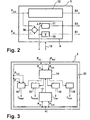
- In Fig. 2 ist eine Ausführungsform der in Fig. 1 gezeigten Regelungseinrichtung 5 detaillierter dargestellt. Die Regelungseinrichtung 5 weist den in Fig. 1 gezeigten Regler 6 auf, der an einem Summationspunkt 39 die Differenz ΔP zwischen dem Sollwert PSoll und dem Istwert PIst bildet. Diese Differenz ΔP wird einem Verstärkungsglied 10 und einem Dreipunktschalter 11 zugeführt. Außerdem kann die Regeldifferenz ΔP z.B. von der Regelungseinrichtung 5 an ein weiteres nicht gezeigtes beliebiges Modul der Steuereinheit ausgegeben werden. In dieser Ausführungsform gibt das Verstärkungsglied 10 die erste Stellgröße S1 aus. Der Verstärkungsfaktor V des Verstärkungsgliedes 10 kann z.B. in Abhängigkeit von der Regeldifferenz ΔP geändert werden. Dieses erfolgt vorzugsweise während einer Krafthaltephase, so daß der Verstärkungsfaktor V optimal eingestellt werden kann. Der Verstärkungsfaktor V kann z.B. vergrößert werden, wenn die Regeldifferenz ΔP außerhalb eines vorgegebenen Differenzbereichs liegt. Im optimalen Fall kann die Regeldifferenz ΔP gleich Null sein, wobei dann der Differenzbereich um die Nullinie angeordnet sein kann.
- Der Dreipunktschalter 11 kann z.B. drei unterschiedliche dritte Stellgrößen S3 in Abhängigkeit von der Regeldifferenz ΔP ausgeben. So kann die dritte Stellgröße S3 z.B. einen vorgegebenen negativen Wert annehmen, wenn die Regeldifferenz ΔP einen vorgegebenen negativen Schwellenwert unterschreitet. Die dritte Stellgröße S3 kann z.B. gleich einem vorgegebenen positiven Wert sein, wenn die Regeldifferenz ΔP einen vorgegebenen positiven Schwellenwert überschreitet. Liegt die Regeldifferenz ΔP z.B. zwischen dem negativen Schwellenwert und dem positiven Schwellenwert, so kann die dritte Stellgröße S3 z.B. gleich Null sein. Eine Verschiebung der Bereiche ins Positive oder Negative ist auch denkbar. Vorzugsweise ist der Dreipunktschalter 11 nur während einer Haltephase aktiv. Ein entsprechendes Signal kann z.B. von dem Situationserkennungsmodul 7 über die Leitung 13 in die Regelungseinrichtung 5 eingegeben werden.
- Der Regler 6 kann auch einen Differenzierer mit z.B. einem nachgeschalteten Verstärkungsglied und/oder einen Integrierer mit z.B. einem nachgeschalteten Verstärkungsglied enthalten. Das Differenzier- und/oder Integrierglied differenziert bzw. integriert dann die Regeldifferenz ΔP und kann dann z.B. entsprechend weitere Stellgrößen ausgeben. Die jeweiligen Verstärkungsfaktoren der Verstärkungsglieder können z.B. auch in Abhängigkeit von dem vom Situationserkennungsmodul 7 erkannten Betriebszustand geändert werden.
- Die Regelungseinrichtung 5 enthält außerdem eine Vorsteuerung 12, die in Abhängigkeit vom Sollwert PSoll eine entsprechende vierte Stellgröße S4 ausgibt. Die Vorsteuerung 12 kann z.B. ein Verstärkungsglied und/oder ein Differenzierglied mit z.B. einem nachgeschalteten Verstärkungsglied enthalten. Auch hier können die jeweiligen Verstärkungsglieder der Vorsteuerung 12 z.B. nach Maßgabe des vom Situationserkennungsmodul 7 bestimmten Betriebszustandes geändert werden.
- Vorteilhaft wird die vierte Stellgröße S4 in größeren Zeitabständen, z.B. alle 7 ms, ermittelt als die erste S1 und/oder dritte S3 Stellgröße, die z.B. alle 2 ms ermittelt werden können. Dieses hat den Vorteil, daß ein wesentlicher Anteil an Rechenzeit eingespart wird. Häufig ändert sich der Sollwert PSoll nur sehr langsam, so daß auch die Vorsteuerung 12 nicht so schnell arbeiten muß. Dahingegen sollten sich die Stellgrößen des Reglers 6 schnell ändern können, um die Stabilität des Gesamtsystems gewährleisten zu können. Daher sollte der Regler 6 in kürzeren Zeitabständen arbeiten.
- In Fig. 3 ist eine andere Ausführungsform der erfindungsgemäßen Steuereinheit 3 aus Fig. 1 gezeigt. Ihr werden der Istwert PIst und der Sollwert PSoll zugeführt, die über eine Leitung 20, die auch aus mehreren Leitungen bestehen kann, weiteren Einrichtungen zugeführt werden können. Die Steuereinheit 3 enthält ein Organisationsmodul 14, das in Abhängigkeit von dem Istwert PIst und/oder dem Sollwert PSoll unterschiedliche Betriebszustände bestimmen kann und entsprechende Signale jeweils an ein Rampenmodul 15, ein Kraftregelmodul 16, ein Überschwingmodul 18 und ein Ruhemodul 19 ausgeben kann. Die Module 15, 16, 18 und 19 ermitteln dann entsprechend dem jeweiligen Betriebszustand eine Ansteuergröße IRampe, IRegel, IUder bzw. IRuhe. Die Steuereinheit 3 kann dann daraus die entsprechende Ansteuergröße I auswählen und ausgeben.
- Weiterhin weist die Steuereinheit 3 ein Überwachungsmodul 17 auf, das den Sollwert PSoll von dem Istwert PIst subtrahieren kann, um eine Regelabweichung Pdiff zu erhalten, und das außerdem die Regelabweichung Pdiff differenzieren kann, um die Änderungsgeschwindigkeit der Regelabweichung Ṗdiff zu erhalten. Das Überwachungsmodul 17 bestimmt dann z.B. einen Überschwingbetriebszustand, wenn die Regelabweichung Pdiff größer als ein Überschwingwert Ü ist und z.B. zusätzlich die positive Änderungsgeschwindigkeit der Regelabweichung Ṗdiff größer als ein Überschwingänderungswert ΔÜ ist. Das Überwachungsmodul 17 kann dann ein entsprechendes Signal an das Organisationsmodul 14 ausgeben. Der Überschwingwert Ü kann z.B. in einem Bereich zwischen 2 bar und 10 bar, beispielsweise bei 6 bar liegen. Der Überschwingänderungswert ΔÜ kann in einem Bereich zwischen 5 bar/s und 20 bar/s, beispielsweise bei 10 bar/s liegen.
- Die Regelabweichung Pdiff kann der Regeldifferenz ΔP des Reglers 6 entsprechen und könnte dann auch z.B. von diesem ermittelt werden. Ebenso könnte die Änderungsgeschwindigkeit der Regelabweichung Ṗdiff dann über ein Differenzierglied des Reglers 6 ermittelt werden. Die Regelabweichung Pdiff und die Änderungsgeschwindigkeit der Regelabweichung Pdiff können dann z.B. vom Regler 6 dem Überwachungsmodul 17 zugeführt werden, das dann auf die Eingangsgrößen Istwert PIst und Sollwert PSoll verzichten kann. Die Arbeitsweise der einzelnen Module der Fig. 3 wird später anhand der weiteren Figuren näher erläutert.
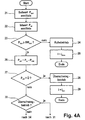
- In Fig. 4 ist ein Flußdiagramm einer erfindungsgemäßen Ausführungsform gezeigt. In Fig. 4A wird zunächst im Schritt 21 der Sollwert Psoll ermittelt. Danach wird im Schritt 22 der Istwert PIst ermittelt. Anschließend wird im Schritt 23 abgefragt, ob der Sollwert PSoll größer oder gleich einem Sollschwellenwert SWSoll ist, der z.B. in einem Bereich zwischen 0 und 1 bar, beispielsweise bei 0,2 bar liegen kann. Ist dieses nicht der Fall, wird im Schritt 24 ein Ruhebetriebszustand ermittelt und entsprechend in den Ruhebetrieb übergegangen. Dabei wird im anschließenden Schritt 25 die Ansteuergröße I gleich einer Ruheansteuergröße IRuhe gesetzt, die das Stellglied 4 nicht ansteuert. Die Ruheansteuergröße IRuhe kann z.B. gleich Null sein. Wird die Abfrage im Schritt 23 bejaht, d.h., daß der Sollwert PSoll größer als der Sollschwellenwert SWSoll ist, wird im Schritt 26 der Sollwert PSoll von dem Istwert PIst abgezogen, woraus sich die Regelabweichung Pdiff ergibt. Danach wird im Schritt 27 abgefragt, ob die Regelabweichung Pdiff größer als der Überschwingwert Ü ist. Ist dies der Fall, wird im Schritt 28 ein Überschwingbetriebszustand ermittelt und entsprechend in den Überschwingbetrieb übergegangen. Dementsprechend wird im nachfolgenden Schritt 29 die Ansteuergröße I gleich einer minimalen Ansteuergröße Imin gesetzt, die gleich der Ruheansteuergröße IRuhe sein kann. Wird die Abfrage im Schritt 27 verneint, d.h., daß die Regelabweichung Pdiff kleiner oder gleich dem Überschwingwert Ü ist, wird im Schritt 30 abgefragt, ob sich die Bremsanlage im Überschwingbetrieb befindet. Ist dies der Fall, wird zum Schritt 31 der Fig. 4B übergegangen. Ist dies nicht der Fall, wird zum Schritt 34 der Fig. 4B übergegangen.
- In Fig. 4B wird zunächst im Schritt 31 abgefragt, ob die Zeitdauer des Überschwingbetriebszustandes kleiner als eine Haltezeitdauer thalt ist. Ist dies der Fall, wird die Ansteuergröße I auf einen Haltewert Ihalt gesetzt. Wird die Abfrage im Schritt 31 verneint, d.h., daß die Zeitdauer des Überschwingbetriebszustands größer oder gleich der Haltezeitdauer thalt ist, wird im Schritt 33 das Ende des Überschwingbetriebszustandes bestimmt. Daran anschließend wird zur Bestimmung eines neuen Betriebszustandes im Schritt 34 abgefragt, ob der Istwert PIst kleiner als ein Istschwellenwert SWIst ist. Ist dies der Fall, wird im Schritt 35 ein Rampenbetriebszustand ermittelt und entsprechend in den Rampenbetrieb übergegangen. Dementsprechend wird im nachfolgenden Schritt 36 die Ansteuergröße I auf einen Rampenwert IRampe gesetzt. Wird die Abfrage im Schritt 34 verneint, d.h., daß der Istwert PIst größer oder gleich dem Istschwellenwert SWIst ist, wird im Schritt 37 ein Kraftregelbetriebszustand ermittelt und entsprechend in den Kraftregelbetrieb übergegangen. Dementsprechend wird im nachfolgenden Schritt 38 die Ansteuergröße I auf einen Regelwert IRegel gesetzt.
- Aus der Fig. 4 wird deutlich, daß es in der dort gezeigten Ausführungsform wichtig sein kann, wie groß der Sollwert PSoll ist. Ist er kleiner als der Sollschwellenwert SWSoll, so wird ein Ruhebetriebszustand aufrechterhalten, der solange andauert, bis der Sollwert PSoll größer oder gleich dem Sollschwellenwert SWSoll ist. Erst dann können die weiteren Betriebszustände, die auch als aktive Betriebszustände bezeichnet werden können, bestimmt werden. Das hat den Vorteil, daß ungewollte Störungen des Sollwertes PSoll, z.B. Abweichungen von Null, nicht bereits zu einer Ansteuerung des Stellglieds 4 führen, da eine Bremsung noch nicht gewünscht ist. Der Sollschwellenwert SWSoll kann z.B. bei 0,2 bar liegen.
- Im Ruhebetrieb muß die Ansteuergröße I nicht notwendigerweise auf Null gesetzt werden, sondern sie kann auch auf einem kleinen Wert gehalten werden, der nicht dazu geeignet ist, das Stellglied 4 anzusteuern. Insbesondere bei der Ansteuerung eines Elektromagneten zur Ansteuerung eines Ventils bedarf es eines Mindeststromes, um einen Istdruck PIst zu erzeugen bzw. erfassen zu können.
- Weiterhin ist in der Ausführungsform der Fig. 4 der Überschwingbetriebszustand allen anderen aktiven Betriebszuständen übergeordnet. Sobald in einem der aktiven Betriebszustände ein Überschwingen dadurch erkannt wird, daß die Regelabweichung Pdiff größer als der Überschwingwert Ü ist, wird in den Überschwingbetrieb übergegangen. Dieser Betriebszustand wird erst beendet, wenn die Ansteuergröße I für eine Zeitdauer thalt auf einem Haltewert Ihalt gehalten wurde. Es sind jedoch auch andere Bedingungen für die Beendigung des Überschwingbetriebszustandes denkbar. Diese könnten in Abhängigkeit von der Regelabweichung Pdiff, der Änderung der Regelabweichung Ṗdiff oder z.B. auch in Abhängigkeit von dem Istwert PIst oder dem Sollwert PSoll festgelegt werden.
- Der Rampenbetriebszustand wird eingesetzt, um den Istwert PIst möglichst schnell und ohne Überschwingen auf den Istschwellenwert SWIst zu bringen. Dieser Wert kann z.B. in einem Bereich zwischen 0 und 1 bar, beispielsweise bei 0,1 bar liegen. Erst dann kann es sinnvoll sein, die Bremskraft im Kraftregelbetriebszustand zu regeln.
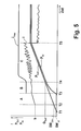
- Fig. 5 gibt einen Überblick über einige mögliche Betriebszustände bzw. Phasen. In dem dargestellten Diagramm sind der Verlauf der Ansteuergröße I, des Sollwertes PSoll und des Istwertes PIst in Abhängigkeit von der Zeit dargestellt. Zum Zeitpunkt T1 beginnt der Sollwert PSoll zu steigen. Die Bremsanlage befindet sich jedoch solange im Ruhezustand, bis der Sollwert PSoll zum Zeitpunkt T2 den Sollschwellenwert SWSoll erreicht. Dann wird zum Rampenbetriebszustand, gekennzeichnet durch den Bereich A, übergegangen, in dem z.B. das Rampenmodul 15 die Ansteuergröße I vorgeben kann.
- Hierbei wird die Ansteuergröße I zunächst sprungartig auf einen Wert h (Sprunghöhe) gesetzt. Danach kann die Ansteuergröße I entsprechend einer Geraden mit einer vorgegebenen Steigung verlaufen. Ein anders ausgebildeter, vorzugsweise ansteigender Verlauf ist auch möglich. Zum Zeitpunkt T3 hat der Istwert PIst den Istschwellenwert SWIst erreicht. Danach wird in den Kraftregelbetriebszustand, gekennzeichnet durch die Bereiche B und C, übergegangen, in dem das Kraftregelmodul 16 die Ansteuergröße I ermitteln kann. Hierbei kann die Ansteuergröße I z.B. von der Regelungseinrichtung 5 ermittelt werden. Um einen glatten Übergang zwischen dem Rampenbetriebszustand und dem Kraftregelbetriebszustand zu ermöglichen, kann z.B. während einer Übergangsphase B die Änderungsgeschwindigkeit der Ansteuergröße İ, vorzugsweise der Betrag der Änderungsgeschwindigkeit der Ansteuergröße |İ| auf einen Maximalwert İmax begrenzt werden. Dadurch kann z.B. eine gleiche Steigung der Ansteuergröße I zum Zeitpunkt T3 beim Übergang von Bereich A zu B und ebenso zum Zeitpunkt T4 beim Übergang vom Bereich B zu C ermöglicht werden. Im Bereich C ist ab dem Zeitpunkt T4 die Übergangsphase B beendet. In der in Fig. 5 gezeigten Ausführungsform ist der Wert İmax während der Übergangsphase B konstant und steigt zu Beginn der nachfolgenden Phase C auf einen endgültigen Wert İmax an. In einer anderen Ausführungsform ist es jedoch denkbar, daß der Wert İmax bereits während der Übergangsphase B auf einen endgültigen Wert ansteigt.
- Der Wert bzw. der Verlauf des Maximalwertes İmax kann auch nach Maßgabe des Sollwertes Psoll bzw. des Sollwertverlaufes eingestellt werden. Hierfür kann ein Grenzsollwert Gsoll vorgesehen sein, dessen Wert in einem Bereich zwischen 1 bar und 5 bar, beispielsweise bei 2 bar liegen kann. Es kann dann z.B. der Sollwert Psoll mit dem Grenzsollwert Gsoll verglichen werden. Ist der Sollwert Psoll kleiner als der Grenzsollwert Gsoll und steigt der Sollwert Psoll an, so kann der Maximalwert İmax auf einen konstanten Wert eingestellt werden. Tritt ein leichter Überschwinger (Pdiff)auf, kann sich der Maximalwert İmax proportional zu Pdiff erhöhen, damit der Regler den Überschwinger ausregeln kann. Ist der Sollwert PSoll konstant oder wird kleiner, so kann der Maximalwert Imax nach einer vorgegebenen Funktion, z.B. exponentiell, auf seinen endgültigen Wert ansteigen. Dasselbe kann gelten, wenn der Sollwert größer oder gleich dem Grenzsollwert Gsoll ist.
- Vorzugsweise wird der Maximalwert İmax quasi sprungförmig auf seinen endgültigen Wert hochgesetzt, wenn ein Überschwingbetriebszustand ermittelt wird, damit die Ansteuergröße I möglichst schnell geändert, vorzugsweise herabgesetzt werden kann, um dem Überschwingen entgegenzuwirken.
- Zum Zeitpunkt T5 sind der Sollwert PSoll und der entsprechend geregelte Istwert PIst konstant. Es kann dann z.B. eine Haltephase erkannt werden, während der die Ansteuergröße I verringert werden kann.
- Fig. 6 zeigt, wie die Vorgabe der Ansteuergröße I im Rampenbetriebszustand in Abhängigkeit von der Änderungsgeschwindigkeit des Sollwertes PSoll, d.h. der Steigung des Sollwertverlaufes angepaßt werden kann. Die Sprunghöhe h wird in etwa auf den Wert eingestellt, der benötigt wird, um einen Istwert PIst, wie z.B. einen Druck in einem Tandemhauptzylinder, erfassen zu können. Dieser Wert h kann fest abgespeichert sein, kann z.B. aber auch während des Betriebes der Bremsanlage jeweils neu optimiert werden. Näheres dazu wird später anhand der Fig. 7 erläutert. In Fig. 6 sind die Verläufe der Ansteuergröße I, des Sollwertes Psoll und des Istwertes PIst für zwei verschiedene Sollwertverläufe dargestellt. Der eine Fall ist jeweils in durchgezogenen Linien gezeigt, und der andere Fall in Strich-Punkt-Linien. Die Sprunghöhe h ist in beiden Fällen gleich. Im ersten Fall der Strich-Punkt-Linien verläuft der Sollwert PSoll steiler, d.h., es soll z.B. schneller und/oder mit größerer Kraft gebremst werden. Dementsprechend ist in dieser Ausführungsform der Verlauf der Ansteuergröße I im Rampenbetriebszustand steiler, damit der Istwert PIst dem Sollwert PSoll schneller folgen kann. Im ersten Fall erreicht der Istwert PIst zum Zeitpunkt T3 den Istschwellenwert SWIst. Im zweiten Fall der durchgezogenen Linien ist der Verlauf des Sollwertes PSoll nicht so steil, weshalb dementsprechend die Steigung des Verlaufs der Ansteuergröße I geringer ist. Dadurch erreicht der Istwert PIst im zweiten Fall erst zum späteren Zeitpunkt T3' den Istschwellenwert SWIst. Die Steigung der Rampe (Gerade) von der Ansteuergröße I kann insbesondere gleich der Steigung des Sollwertverlaufs sein. Die Dauer des Rampenbetriebszustandes ist in Fig. 6 in beiden Fällen, Bereich T2 bis T3 bzw. Bereich T2' bis T3', in etwa gleich lang.
- Die Dauer des Rampenbetriebszustandes tRampe kann überwacht werden. Dafür kann ein Zeitbereich vorgegeben werden, innerhalb dessen die Zeitdauer tRampe liegen darf. Dieser Bereich wird durch einen unteren Zeitgrenzwert Tu, der z.B. 120 ms betragen kann, und einen oberen Zeitgrenzwert To, der z.B. 150 ms betragen kann, begrenzt. Die Zeitgrenzwerte können je nach Bremsanlage eingestellt werden. Während eines Rampenbetriebszustandes kann dann z.B. die Dauer dieses Betriebszustandes bestimmt und mit den Zeitgrenzwerten verglichen werden. Liegt die Zeitdauer tRampe unterhalb des unteren Zeitgrenzwertes Tu, wird z.B. die Sprunghöhe h um einen vorgegebenen Verringerungswert W1 verringert. Als zusätzliche Bedingung für die Verringerung der Sprunghöhe h kann z.B. zusätzlich vorgegeben werden, daß der Unterschied zwischen der Änderungsgeschwindigkeit des Sollwertes ṖSoll und der Änderungsgeschwindigkeit des Istwertes ṖIst einen Änderungsschwellenwert nicht über- und/oder unterschreiten darf. Bei Vorliegen einer oder beider Bedingungen könnte dann die Sprunghöhe h verringert werden.
- Liegt dagegen die Zeitdauer tRampe des Rampenbetriebszustands oberhalb des oberen Zeitgrenzwertes To, so kann die Sprunghöhe h z.B. um einen Erhöhungswert W2 erhöht werden.
- Durch die Verringerung der Sprunghöhe h kann die Zeitdauer tRampe verlängert werden, und zusätzlich kann die Geräuschentwicklung der Bremsanlage, insbesondere des Elektromagneten bzw. des Ventils verringert werden. Durch die Erhöhung der Sprunghöhe h kann die Zeitdauer tRampe verkürzt werden. Der Unterschied zwischen den Änderungsgeschwindigkeiten des Sollwertes PSoll und des Istwertes PIst kann z.B. durch Auswerten der Änderungsgeschwindigkeit der Regelabweichung Ṗdiff ermittelt werden.
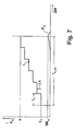
- Die Sprunghöhe h kann z.B. während des Ruhebetriebszustandes, am Ende der Herstellung des Fahrzeugs zur Initialisierung, nach jeder Zündung oder auch z.B. während einer automatischen Abstandsregelung (ACC) unter bestimmten Bedingungen ermittelt werden. Die Vorgehensweise ist in Fig. 7 beispielhaft erläutert. Dort sind während dieser sog. Lernphase der Verlauf der Ansteuergröße I und des Istwertes PIst in Abhängigkeit von der Zeit dargestellt. Zu Beginn kann die Ansteuergröße I z.B. auf einen Anfangswert hA, z.B. 1A gesetzt und danach stufenweise erhöht werden. Dies kann z.B. treppenförmig mit einer Stufenbreite Th und einer Stufenhöhe Δh erfolgen. Während dieser Zeit wird z.B. der Istwert PIst erfaßt. Die Ansteuergröße I wird dann z.B. solange erhöht, bis ein tatsächlicher Istwert PIst erfaßt wird. Dieser Wert kann z.B. etwa gleich dem Istschwellenwert SWIst sein. Der dann anliegende Wert der Ansteuergröße I wird dann z.B. als Sprunghöhe h gespeichert. Anschließend kann dann die Ansteuergröße I wieder verringert werden, womit die Lernphase beendet ist.
- Die Zeitdauer Th,ges der Lernphase kann z.B. auf einen minimalen und/oder maximalen Wert begrenzt werden. Sie kann z.B. 3 s betragen. Die Stufenbreite Th kann z.B. in einem Bereich zwischen 10 ms und 1 s liegen, beispielsweise 100 ms betragen. Die Stufenhöhe Δh kann von der Genauigkeit der Erfassung des Istwert-Sensors abhängen, kann z.B. maximal 50 mA betragen. Die Sprunghöhe h kann z.B. bei 2,2 A liegen. Die in bezug auf die Lernphase genannten Größen können erheblich in Abhängigkeit von dem verwendeten Bremssystem variieren.
- Anhand von Fig. 8 wird nun beispielhaft der Überschwingbetriebszustand näher erläutert. In dem Diagramm sind die Verläufe der Ansteuergröße I, des Sollwertes PSoll, des Istwertes PIst und der Änderungsgeschwindigkeit der Regelabweichung Ṗdiff für zwei verschiedene Fälle dargestellt. Der erste Fall, dargestellt mit durchgezogenen Linien, zeigt die Verläufe für den Fall, daß das Überschwingmodul 18 nicht vorgesehen ist. Der zweite Fall, dargestellt durch die Strich-Punkt-Linien, zeigt die Verläufe unter Einwirkung des Überschwingmoduls 18 im Überschwingbetriebszustand. Der Solldruck PSoll verläuft in beiden Fällen gleich. Ab dem Zeitpunkt T3 ist ein grauer Bereich 40 oberhalb des Sollwertes PSoll eingezeichnet. Dieser kennzeichnet den Bereich, den der Istwert PIst nicht überschreiten darf. Der untere graue Bereich 41, der ebenfalls ab dem Zeitpunkt T3 beginnt, bezeichnet den Bereich, den die Änderungsgeschwindigkeit Ṗdiff nicht unterschreiten sollte. In der dargestellten Ausführungsform muß der obere Bereich 40 von dem Istwert PIst überschritten sein und zusätzlich der untere Bereich 41 von der Änderungsgeschwindigkeit Ṗdiff unterschritten sein, damit ein Überschwingen erkannt wird. Der Vorteil liegt darin, daß einem hohen Überschwingen des Istwertes PIst gegenüber dem Sollwert PSoll durch das Überschwingmodul 18 entgegengewirkt werden kann, wohingegen ein geringes Überschwingen z.B. von dem Kraftregelmodul ausgeregelt werden kann. In diesem Beispiel wird ein Überschwingen erst nach dem Beginn des Kraftregelbetriebszustands überprüft.
- Der Bereich zwischen den Zeitpunkten T6 und T8 stellt den Bereich des Überschwingbetriebszustandes dar. Die Änderungsgeschwindigkeit der Regelabweichung Ṗdiff unterschreitet bereits vor dem Zeitpunkt T6 (durchgezogene Linie) den erlaubten Bereich 41. Hierbei wird jedoch ein Überschwingen noch nicht erkannt, da der Istwert PIst noch innerhalb des erlaubten Bereiches 40 liegt. Erst bei Erreichen der Grenze des Bereiches 40 zum Zeitpunkt T6 wird der Überschwingbetriebszustand bestimmt, da auch weiterhin die Änderungsgeschwindigkeit der Regelabweichung Ṗdiff den Bereich 41 unterschritten hat. Zu Beginn des Überschwingbetriebszustandes kann die Ansteuergröße I auf den Minimalwert Imin gesetzt (Strich-Punkt-Linie) werden. Zum Zeitpunkt T7 liegen sowohl der Istwert PIst als auch die Änderungsgeschwindigkeit der Regelabweichung Ṗdiff innerhalb der jeweiligen Bereiche 40 und 41, so daß die Ansteuergröße I z.B. auf einen Haltewert Ihalt gesetzt werden kann, der unterhalb der Sprunghöhe h liegen kann. Die Ansteuergröße I kann dann z.B. für eine Zeitdauer thalt auf dem Haltewert Ihalt gehalten werden. Die Haltezeitdauer thalt kann z.B. fest gespeichert sein. Sie kann aber auch in Abhängigkeit von bestimmten Größen variabel gehalten werden.
- Nach Beendigung des Überschwingbetriebszustands zum Zeitpunkt T8 wird in den normalen Kraftregelbetrieb übergegangen, in dem z.B. das Kraftregelmodul 16 wieder die Ansteuergröße I ermittelt.
- Eine häufige Ursache für ein Überschwingen des Istwertes PIst kann z.B. ein Durchgehen des Magnetankers des Elektromagneten sein; d.h. dieser geht in die Sättigung und verbleibt unabhängig vom Strom in einer Extremposition (Anschlag), die z.B. einer vollständigen Ventilöffnung entspricht. In diesem Fall ist daher ein Zusammenhang zwischen dem Magnetstrom, d.h. der Ansteuergröße I und der Ventilposition, d.h. der Bremsdrucksteuerung, nicht mehr garantiert. Deshalb hilft häufig nur noch ein abruptes Aussetzen der Kraftregelung und ein Zurücknehmen des Stromes z.B. auf Imin, bis der Magnetanker von seinem Anschlag wieder absetzt. Das Überschwingmodul 18 kann somit das System bei einer instabil gewordenen Regelstrecke wieder stabilisieren.
- Die erfindungsgemäße Vorrichtung kann ganz, oder teilweise auf einem Rechner realisiert sein, so daß das implementierte Verfahren digital durchgeführt werden kann. Dabei können die Abtastschritte jedoch so klein sein, daß das Verfahren als quasi-kontinuierlich angesehen werden kann. Bei ausreichender Werteauflösung können auch die Werte als quasi-kontinuierlich angesehen werden. Entsprechend sind die angegebenen Werte, wie z.B. der Istwert PIst oder der Sollwert PSoll, den tatsächlichen Werten entsprechende Größen bzw. Signale, die z.B. in einem Rechner verarbeitet werden können. Der Rechner kann dementsprechend die Ansteuergröße als Signal ausgeben, das dann z.B. noch in eine entsprechende Ansteuergröße zur Ansteuerung umgewandelt werden kann. Im Falle eines Magnetstromes kann dieses z.B. bedeuten, daß die Ansteuergröße in Form von PWM-Signalen vorliegt. Die Zeiten bzw. Zeitdauern können in Form von Rechnerzählwerten vorliegen und/oder ausgewertet werden.
- Die obigen Ausführungen zeigen, daß die Merkmale der erfindungsgemäßen Vorrichtung äußerst variabel an beliebige Situationen angepaßt werden können und somit eine deutliche Verbesserung z.B. in Bezug auf die Regelgüte gegenüber herkömmlichen Bremsregelungen darstellen. Sie können ohne weiteres für weitere nicht genannte Bremssituationen bzw. -zustände erweitert werden, da die genannten Zustände nicht abschließend sind.
Claims (14)
- Vorrichtung zur Bremskraftsteuerung einer Bremsanlage mit einer Sensorik (1) zur Ermittlung eines Istwertes (PIst) einer eine Bremsung verursachenden Bremskraft, einer Ermittlungseinrichtung (2) zum Ermitteln eines Sollwertes (PSoll) für die Bremskraft und einer Steuereinheit (3) zum Ermitteln einer Ansteuergröße (I) für ein Stellglied (4) zum Einstellen der Bremskraft, wobei die Steuereinheit (3) den Sollwert (PSoll) von der Ermittlungseinrichtung (2) und den Istwert (PIst) von der Sensorik (1) empfängt, einen von zumindest zwei unterschiedlichen Betriebszuständen der Bremsanlage nach Maßgabe des Sollwertes (PSoll) und/oder des Istwertes (PIst) bestimmt, die Ansteuergröße (I) für das Stellglied (4) in Abhängigkeit von dem Sollwert (PSoll) und/oder dem Istwert (PIst) und nach Maßgabe des bestimmten Betriebszustandes ermittelt und die Ansteuergröße (I) an das Stellglied (4) ausgibt, dadurch gekennzeichnet, dass die Steuereinheit (3) enthält:- ein Organisationsmodul (14), das den Istwert (PIst) mit einem Istschwellenwert (SWIst) vergleicht und• dann, wenn der Istwert (PIst) kleiner als der Istschwellenwert (SWIst) ist, einen Rampenbetriebszustand ermittelt, und• ansonsten einen Kraftregelbetriebszustand ermittelt,- ein Rampenmodul (15), das bei Vorliegen des Rampenbetriebszustands ein entsprechendes Signal von dem Organisationsmodul (14) erhält und dann die Ansteuergröße (I) gemäß einer vorgegebenen Zeitfunktion ändert, insbesondere erhöht, und- ein Kraftregelmodul (16), an dessen Eingang der Istwert (PIst) und der Sollwert (PSoll) anliegen und das bei Vorliegen des Kraftregelbetriebszustands ein entsprechendes Signal von dem Organisationsmodul (14) erhält und dann die Ansteuergröße (I) in Abhängigkeit von dem Istwert (PIst) und dem Sollwert (PSoll) ermittelt.
- Vorrichtung nach Anspruch 1, bei der die Steuereinheit (3) eine Regelungseinrichtung (5) enthält, an der eingangsseitig der Istwert und der Sollwert anliegen und die einen Regler (6) enthält, der in Abhängigkeit von der Regeldifferenz (ΔP) zwischen dem Sollwert (PSoll) und dem Istwert (PIst) eine erste Stellgröße (S1) für das Stellglied (4) ermittelt, wobei die Steuereinheit (3) ein Situationserkennungsmodul (7) enthält, das als Betriebszustand eine Kraftaufbauphase, eine Kraftabbauphase und eine Krafthaltephase erkennt und ein entsprechendes Signal an ein nachfolgendes nichtlineares Übertragungsglied (8) mit einer Dreipunktkennlinie ausgibt, das eine entsprechende zweite Stellgröße (S2) für das Stellglied (4) ausgibt, wobei die Steuereinheit (3) die erste Stellgröße (S1) mit der zweiten Stellgröße (S2) kombiniert, um die Ansteuergröße (I) für das Stellglied (4) zu erhalten.
- Vorrichtung nach Anspruch 2, bei der der Regler (6) ein Verstärkungsglied (10) zum Verstärken der Regeldifferenz (ΔP) enthält und bei dem während einer Krafthaltephase dann, wenn die Regeldifferenz (ΔP) einen erlaubten Bereich über- oder unterschreitet, eine Änderung des Verstärkungsfaktors (V) des Verstärkungsgliedes (10) bewirkt wird.
- Vorrichtung nach Anspruch 2 oder 3, bei der der Regler (6) einen Dreipunktschalter (11) enthält, an dessen Eingang die Regeldifferenz (ΔP) anliegt und der während der Krafthaltephase in Abhängigkeit von der Regeldifferenz (ΔP) eine dritte Stellgröße (S3) für das Stellglied (4) ausgibt, wobei die Steuereinheit (3) die dritte Stellgröße (S3) mit der ersten (S1) und zweiten Stellgröße (S2) kombiniert, um die Ansteuergröße (I) zu erhalten.
- Vorrichtung nach zumindest einem der Ansprüche 2 bis 4, bei der die Regelungseinrichtung (5) eine Vorsteuerung (12) enthält, die in Abhängigkeit von dem Sollwert (PSoll) eine vierte Stellgröße (S4) für das Stellglied (4) ermittelt, wobei die Steuereinheit (3) die vierte Stellgröße (S4) mit der ersten (S1), zweiten (S2) und dritten Stellgröße (S3) kombiniert, um die Ansteuergröße (I) zu erhalten, und wobei die Vorsteuerung (12) die vierte Stellgröße (S4) in größeren Zeitabständen ermittelt als der Regler (6) die erste (S1) und/oder dritte Stellgröße (S3).
- Vorrichtung nach einem der Ansprüche 1 bis 5, bei der das Kraftregelmodul (16) der Regelungseinrichtung (5) nach zumindest einem der Ansprüche 2 bis 5 entspricht.
- Vorrichtung nach Anspruch 1, bei der die Zeitfunktion einen Sprung einer bestimmten Sprunghöhe (h) und/oder eine Gerade mit einer bestimmten Rampensteigung (s) aufweist.
- Vorrichtung nach Anspruch 7, bei der die Sprunghöhe (h) etwa derjenigen Ansteuergröße (I) entspricht, die benötigt wird, um eine minimale Bremskraft zu erzeugen, und/oder bei dem die Rampensteigung (s) in Abhängigkeit von der Änderungsgeschwindigkeit des Sollwertes (ṖSoll) bestimmt wird.
- Vorrichtung nach Anspruch 7 oder 8, bei der das Rampenmodul (15) die Sprunghöhe (h)- dann, wenn die Zeitdauer (tRampe) des Rampenbetriebszustands kleiner als ein unterer Zeitgrenzwert (Tu) ist und der Unterschied zwischen der Änderungsgeschwindigkeit des Sollwertes (Ṗsoll) und der Änderungsgeschwindigkeit des Istwertes (ṖIst) einen Änderungsschwellenwert (ΔSW) überschreitet, um einen Verringerungswert (W1) verringert, und/oder- dann, wenn die Zeitdauer (tRampe) des Rampenbetriebszustands größer als ein oberer Zeitgrenzwert (To) ist, um einen Erhöhungswert (W2) erhöht.
- Vorrichtung nach zumindest einem der Ansprüche 7 bis 9, bei der das Kraftregelmodul (16) zu Beginn des Kraftregelbetriebszustands während einer Übergangszeitdauer (tü) die Änderungsgeschwindigkeit der Ansteuergröße (i) auf eine maximale Änderungsgeschwindigkeit (İmax) begrenzt und die maximale Änderungsgeschwindigkeit (İmax) der Ansteuergröße zeitabhängig erhöht.
- Vorrichtung nach zumindest einem der Ansprüche 7 bis 10, bei der die Steuereinheit (3) enthält:- ein Überwachungsmodul (17), das den Sollwert (PSoll) von dem Istwert (PIst) subtrahiert, um eine Regelabweichung (Pdiff) zu erhalten, und einen Überschwingbetriebszustand ermittelt, wenn die Regelabweichung (Pdiff) größer als ein Überschwingwert (Ü) ist und die positive Änderungsgeschwindigkeit der Regelabweichung (Ṗdiff) größer als ein Überschwingänderungswert (ΔÜ) ist, und ein entsprechendes Signal an das Organisationsmodul (14) ausgibt, und- ein Überschwingmodul (18), dem bei Vorliegen des Überschwingbetriebszustands vom Organisationsmodul (14) ein entsprechendes Signal zugeführt wird und das dann die Ansteuergröße (I) auf ein Ansteuerminimum (Imin) setzt.
- Vorrichtung nach Anspruch 11, bei der das Überschwingmodul (18) im Überschwingbetriebszustand dann, wenn die Regelabweichung (Pdiff) kleiner als oder gleich dem Überschwingwert (Ü) ist, die Ansteuergröße (I) auf einen Haltewert (Ihalt) setzt, der größer als das Ansteuerminimum (Imin) und kleiner als die Sprunghöhe (h) ist.
- Vorrichtung nach Anspruch 11 oder 12, bei der das Organisationsmodul (14) einen dem Überschwingbetriebszustand folgenden Kraftregelbetriebszustand ermittelt, wenn die Ansteuergröße (I) für eine Haltezeitdauer (thalt) auf dem Haltewert (Ihalt) gehalten wurde.
- Vorrichtung nach zumindest einem der Ansprüche 1 bis 13, bei der das Organisationsmodul (14) den Sollwert (PSoll) mit einem Sollschwellenwert (SWSoll) vergleicht und dann, wenn der Sollwert (PSoll) kleiner als der Sollschwellenwert (SWSoll) ist, einen Ruhebetriebszustand ermittelt, wobei die Steuereinheit (3) ein Ruhemodul (19) enthält, das bei Vorliegen des Ruhebetriebszustands ein entsprechendes Signal von dem Organisationsmodul (14) erhält und dann die Ansteuergröße (I) auf einen das Stellglied (4) nicht ansteuernden Ruhewert (IRuhe) setzt.
Applications Claiming Priority (5)
| Application Number | Priority Date | Filing Date | Title |
|---|---|---|---|
| DE19849411 | 1998-10-27 | ||
| DE19849411 | 1998-10-27 | ||
| DE19940252 | 1999-08-25 | ||
| DE19940252A DE19940252A1 (de) | 1998-10-27 | 1999-08-25 | Vorrichtung und Verfahren zur Bremskraftsteuerung einer Bremsanlage |
| PCT/EP1999/008124 WO2000024617A2 (de) | 1998-10-27 | 1999-10-27 | Vorrichtung und verfahren zur bremskraftsteuerung einer bremsanlage |
Publications (2)
| Publication Number | Publication Date |
|---|---|
| EP1117578A2 EP1117578A2 (de) | 2001-07-25 |
| EP1117578B1 true EP1117578B1 (de) | 2006-06-21 |
Family
ID=26049777
Family Applications (1)
| Application Number | Title | Priority Date | Filing Date |
|---|---|---|---|
| EP99970970A Expired - Lifetime EP1117578B1 (de) | 1998-10-27 | 1999-10-27 | Vorrichtung zur bremskraftsteuerung einer bremsanlage |
Country Status (3)
| Country | Link |
|---|---|
| EP (1) | EP1117578B1 (de) |
| DE (1) | DE59913606D1 (de) |
| WO (1) | WO2000024617A2 (de) |
Families Citing this family (1)
| Publication number | Priority date | Publication date | Assignee | Title |
|---|---|---|---|---|
| DE102014215297A1 (de) * | 2014-08-04 | 2016-02-04 | Continental Teves Ag & Co. Ohg | Regelschaltung zur Regelung sowie Schaltungsanordnung zur Steuerung einer Bremsanlage für Kraftfahrzeuge |
Citations (1)
| Publication number | Priority date | Publication date | Assignee | Title |
|---|---|---|---|---|
| DE19511694A1 (de) * | 1995-03-30 | 1996-10-02 | Teves Gmbh Alfred | Bremsanlage für Kraftfahrzeuge |
Family Cites Families (3)
| Publication number | Priority date | Publication date | Assignee | Title |
|---|---|---|---|---|
| DE19624376A1 (de) * | 1996-06-19 | 1998-01-02 | Teves Gmbh Alfred | Bremsanlage für Kraftfahrzeuge |
| DE19624794A1 (de) * | 1996-06-21 | 1998-01-02 | Teves Gmbh Alfred | Bremsanlage für Kraftfahrzeuge |
| DE19718168A1 (de) * | 1997-04-29 | 1998-11-05 | Siemens Ag | Bremskraftverstärker für ein Kraftfahrzeug |
-
1999
- 1999-10-27 EP EP99970970A patent/EP1117578B1/de not_active Expired - Lifetime
- 1999-10-27 DE DE59913606T patent/DE59913606D1/de not_active Expired - Lifetime
- 1999-10-27 WO PCT/EP1999/008124 patent/WO2000024617A2/de not_active Ceased
Patent Citations (1)
| Publication number | Priority date | Publication date | Assignee | Title |
|---|---|---|---|---|
| DE19511694A1 (de) * | 1995-03-30 | 1996-10-02 | Teves Gmbh Alfred | Bremsanlage für Kraftfahrzeuge |
Also Published As
| Publication number | Publication date |
|---|---|
| WO2000024617A3 (de) | 2000-08-03 |
| EP1117578A2 (de) | 2001-07-25 |
| WO2000024617A2 (de) | 2000-05-04 |
| DE59913606D1 (de) | 2006-08-03 |
Similar Documents
| Publication | Publication Date | Title |
|---|---|---|
| EP0669565B1 (de) | Druckregeleinrichtung | |
| DE19654427B4 (de) | Verfahren und Vorrichtung zur Regelung des Drucks in wenigstens einer Radbremse | |
| DE3836471C2 (de) | ||
| EP1478557B1 (de) | Verfahren zum einregeln eines vorgegebenen veränderlichen bremsdruckes | |
| DE19616732B4 (de) | Verfahren und Vorrichtung zur Steuerung der Bremsanlage eines Fahrzeugs | |
| EP0697317B1 (de) | Verfahren und Einrichtung zur Druckregelung | |
| EP1324906A1 (de) | Verfahren und regelsystem zur ansteuerung eines elektronisch regelbaren bremsbetätigungssystems | |
| DE102011076675A1 (de) | Verfahren und Vorrichtung zur Regelung eines elektrohydraulischen Bremssystems für Kraftfahrzeuge | |
| EP3354527B1 (de) | Verfahren zum einstellen von bremsdrücken eines kraftfahrzeugs über ansteuerung eines drucksteuerventils, bremsanlage zur durchführung des verfahrens sowie kraftfahrzeug | |
| DE19615805A1 (de) | Verfahren und Vorrichtung zur Steuerung der Bremsanlage eines Fahrzeugs | |
| DE19848960B4 (de) | Verfahren und Vorrichtung zur Steuerung eines Drucksteuerventils, insbesondere einer Bremsanlage | |
| EP0814990A1 (de) | Bremsanlage für kraftfahrzeuge | |
| DE19653230B4 (de) | Verfahren und Vorrichtung zur Steuerung der Bremsanlage eines Fahrzeugs | |
| DE3904573C2 (de) | ||
| DE19739827B4 (de) | Verfahren und Vorrichtung zur Steuerung einer Betriebsgröße eines Kraftfahrzeugs | |
| DE10034873B4 (de) | Verfahren und Bremsanlage zum Regeln des Bremsvorgangs bei einem Kraftfahrzeug | |
| EP0460126B1 (de) | System zur elektronischen steuerung und/oder regelung der leistung einer brennkraftmaschine eines kraftfahrzeugs | |
| EP0473914A2 (de) | System zur Regelung eines Stellwerks in einem Kraftfahrzeug | |
| DE19940252A1 (de) | Vorrichtung und Verfahren zur Bremskraftsteuerung einer Bremsanlage | |
| DE10142040A1 (de) | Verfahren und Regelsystem zur Ansteuerung eines elektronisch regelbaren Bremsbetätigungssystems | |
| EP1028043B1 (de) | Druckregeleinrichtung | |
| EP1140597B1 (de) | Elektronisch steuerbarer bremskraftverstärker | |
| EP0814982B1 (de) | Bremsanlage für kraftfahrzeuge | |
| DE19604220A1 (de) | Verfahren und Vorrichtung zur Regelung bzw. Begrenzung der Fahrgeschwindigkeit eines Fahrzeugs | |
| EP1118517B1 (de) | Fahrzeugbremsanlage |
Legal Events
| Date | Code | Title | Description |
|---|---|---|---|
| PUAI | Public reference made under article 153(3) epc to a published international application that has entered the european phase |
Free format text: ORIGINAL CODE: 0009012 |
|
| 17P | Request for examination filed |
Effective date: 20010426 |
|
| AK | Designated contracting states |
Kind code of ref document: A2 Designated state(s): AT BE CH CY DE DK ES FI FR GB GR IE IT LI LU MC NL PT SE |
|
| RBV | Designated contracting states (corrected) |
Designated state(s): DE FR IT |
|
| 17Q | First examination report despatched |
Effective date: 20050202 |
|
| GRAP | Despatch of communication of intention to grant a patent |
Free format text: ORIGINAL CODE: EPIDOSNIGR1 |
|
| RTI1 | Title (correction) |
Free format text: DEVICE FOR CONTROLLING THE BRAKING POWER OF A BRAKE SYSTEM |
|
| GRAS | Grant fee paid |
Free format text: ORIGINAL CODE: EPIDOSNIGR3 |
|
| GRAA | (expected) grant |
Free format text: ORIGINAL CODE: 0009210 |
|
| AK | Designated contracting states |
Kind code of ref document: B1 Designated state(s): DE FR IT |
|
| PG25 | Lapsed in a contracting state [announced via postgrant information from national office to epo] |
Ref country code: IT Free format text: LAPSE BECAUSE OF FAILURE TO SUBMIT A TRANSLATION OF THE DESCRIPTION OR TO PAY THE FEE WITHIN THE PRESCRIBED TIME-LIMIT;WARNING: LAPSES OF ITALIAN PATENTS WITH EFFECTIVE DATE BEFORE 2007 MAY HAVE OCCURRED AT ANY TIME BEFORE 2007. THE CORRECT EFFECTIVE DATE MAY BE DIFFERENT FROM THE ONE RECORDED. Effective date: 20060621 |
|
| REF | Corresponds to: |
Ref document number: 59913606 Country of ref document: DE Date of ref document: 20060803 Kind code of ref document: P |
|
| ET | Fr: translation filed | ||
| PLBE | No opposition filed within time limit |
Free format text: ORIGINAL CODE: 0009261 |
|
| STAA | Information on the status of an ep patent application or granted ep patent |
Free format text: STATUS: NO OPPOSITION FILED WITHIN TIME LIMIT |
|
| 26N | No opposition filed |
Effective date: 20070322 |
|
| PGFP | Annual fee paid to national office [announced via postgrant information from national office to epo] |
Ref country code: IT Payment date: 20091022 Year of fee payment: 11 Ref country code: FR Payment date: 20091117 Year of fee payment: 11 |
|
| PG25 | Lapsed in a contracting state [announced via postgrant information from national office to epo] |
Ref country code: FR Free format text: LAPSE BECAUSE OF NON-PAYMENT OF DUE FEES Effective date: 20101102 |
|
| REG | Reference to a national code |
Ref country code: FR Ref legal event code: ST Effective date: 20110630 |
|
| PG25 | Lapsed in a contracting state [announced via postgrant information from national office to epo] |
Ref country code: IT Free format text: LAPSE BECAUSE OF NON-PAYMENT OF DUE FEES Effective date: 20101027 |
|
| PGFP | Annual fee paid to national office [announced via postgrant information from national office to epo] |
Ref country code: DE Payment date: 20181031 Year of fee payment: 20 |
|
| REG | Reference to a national code |
Ref country code: DE Ref legal event code: R071 Ref document number: 59913606 Country of ref document: DE |