Technical Field
The present invention relates to an apparatus for
processing panoramic images or the like which have been
photographed in all directions.
Background Art
It is strongly desired to observe surrounding
environments at a certain view point as if the viewer was
at that site. Specifically, if a viewing direction for an
image of scenery photographed during a trip can be freely
varied to display scenery extending in the viewing direction,
the viewer can feel as if he or she was looking around though
he or she is not actually at that site.
If the viewing direction can be freely varied for an image
such as that obtained using a fisheye lens or an
omnidirectional image obtained using a reflection mirror,
which image has a field of view much larger than that obtained
by a normal camera lens, the feeling of being at the site
is further improved.
Japanese Patent Laid-Open No. 9-62861 discloses an
apparatus for storing panoramic images photographed around
a view point moving while traveling through space as well
as a relative-moving position from a certain point.
In reproducing an image, an image extending in a
specified viewing direction is synthesized from the panoramic
image stored in the apparatus, and the synthesized image is
displayed. When the user indicates a next view point or line
of sight, a next image is correspondingly invoked, computed,
and displayed; this operation is repeated.
The view point is a position where an image is
photographed, and the line of sight is a direction in which
a viewer looks at the view point position.
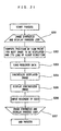
FIG. 21 shows a process loop of image reproduction
according to this conventional technique.
The following description follows this process loop.
S201 is a loop in which an image is repeatedly synthesized
and displayed.
At S202, a view point and a line-of-sight direction for
a traveling path are initially computed. After the start
loop, the next view point position and line-of-sight
direction to be displayed are computed and determined from
a relative movement computed at S206, relative to the current
view point and line-of-sight direction.
At S203, a panoramic image corresponding to the view
point position determined at S202 is loaded.
At S204, an image extending in the line-of-sight
direction determined at S202 is synthesized from the
panoramic image.
At S205, the image synthesized at S204 is displayed.
At S206, a user views the image displayed at S205 to
indicate movement of the view point and the line-of-sight
direction in which a visual angle is moved.
At S207, the process returns to S201 to repeat processing
from S202 to S206.
At S206 the user can command move forward, move backward,
stop, clockwise rotation, counterclockwise rotation, upward
rotation, downward rotation, enlargement, contraction, and
end.
Additionally, by retaining history of the view point
position and line-of-sight direction, this conventional
apparatus can predict the next possible view point position
and line-of-sight direction to be indicated by the user in
order to load a required image in advance, thereby achieving
fast display.
In this manner, for a video photographed in all
directions during movement, the conventional apparatus
repeatedly invokes, for each reproduction, images
photographed at a view point position and in a line-of-sight
direction dependent on the user's command and synthesizes
and displays the images, to provide the user with images that
provide him or her with the feeling of being at the site.
The above described conventional apparatus, however,
still has the following problems:
Disclosure of Invention
It is an object of the present invention to provide an
omnidirectional video output method that enables fast
reproduction and provides users with the feeling of being
at the site.
It is another object of the present invention to provide
an omnidirectional video output method that allows a user
to easily input desired traveling path and line of sight to
a terminal device to receive display of only images on a
required path.
An omnidirectional video output method according to the
present invention comprises transmitting image pickup
position data representing a service area having
omnidirectional images, from a supply center to a terminal
device, and transmitting at least view point information of
desired view point information and line-of-sight information
from the terminal device to the supply center. When only the
view point information is transmitted from the terminal
device to the supply center, only image information for a
traveling path desired by the terminal device is transmitted
from the supply center to the terminal device, which then
processes and outputs the information depending on the
desired view point. When the view point and line-of-sight
information is transmitted from the terminal device to the
supply center, only image information for a traveling path
desired by the terminal device is processed depending on the
desired line of sight based on the view point and line-of-sight
information received from the terminal device and
is then transmitted from the supply center to the terminal
device, which then outputs the information.
According to the configuration of the present invention,
the amount of data in information between the supply center
and the terminal device is reduced to increase the
reproduction speed, thereby providing users with the feeling
of being at the site.
This configuration also improves the input method for
the terminal device to facilitate the operation of inputting
the desired traveling path and line of sight.
In addition, when the terminal device indicates the
desired view point to the supply center, the supply center
presents image pickup position data for omnidirectional
images to the terminal device, which receives, based on the
image pickup position data, image information for a desired
traveling path determined depending on the desired view point.
Accordingly, the user can easily input the desired traveling
path and can continuously view only images on the desired
traveling path in such a manner that the reproduction time
passes smoothly.
Further, if not only the view point information but also
the line-of-sight information is transmitted from the
terminal device to the supply center, the supply center
extracts omnidirectional images from an omnidirectional
image position file based on the view point information,
subsequently processes the images based on the line-of-sight
information, and then transmits only the required image to
the terminal device for display. Consequently, the user can
enjoy an all-image display that provides users with the
feeling of being at the site, regardless of an
arithmetic-operation process speed of the terminal device.
Brief Description of Drawings
FIG. 1 is a block diagram of an omnidirectional video
apparatus according to (Embodiment 1) of the present
invention;
FIG. 2 is a schematic view of the system configuration
of the omnidirectional video apparatus according to this
embodiment;
FIG. 3 is a view useful in explaining the principle of
image pickup of omnidirectional images according to this
embodiment;
FIG. 4 is a schematic view of omnidirectional images
according to this embodiment;
FIG. 5 is a view useful in explaining a traveling path
for a video sensor according to this embodiment;
FIG. 6 is a view useful in explaining an omnidirectional
image position file according to this embodiment;
FIG. 7 is a view useful in explaining a result of display
of all image pickup positions according to this embodiment;
FIG. 8 is a view useful in explaining a result of
indication of an observation path;
FIG. 9 is a schematic view of a expanded image according
to this embodiment;
FIG. 10 is a view useful in explaining a expanded image
file according to this embodiment;
FIG. 11 is a view useful in explaining a window image
according to this embodiment;
FIG. 12 is a view useful in explaining a line-of-sight
indicating means according to this embodiment;
FIG. 13 is a block diagram of an omnidirectional video
apparatus according to (Embodiment 2) of the present
invention;
FIG. 14 is a view useful in explaining a result of
indication of an observation path;
FIG. 15 is a block diagram of an omnidirectional video
apparatus according to (Embodiment 3) of the present
invention;
FIG. 16 is a view useful in explaining a result of display
of all image pickup positions according to this embodiment;
FIG. 17 is a view useful in explaining a result of
indication of an observation path;
FIG. 18 is a block diagram of an omnidirectional video
apparatus according to (Embodiment 4) of the present
invention;
FIG. 19 is a view useful in explaining a result of
indication of an object according to this embodiment;
FIG. 20 is a view useful in explaining a result of
computation for an observation path according this
embodiment; and
FIG. 21 is a block diagram showing an operational
procedure executed by a conventional apparatus.
Best Mode for Carrying Out the Invention
Each embodiment of the present invention will be
explained below with reference to FIGS. 1 to 20.
(Embodiment 1)
FIGS. 1 to 12 show (Embodiment 1).
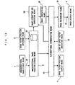
FIG. 1 is an omnidirectional video apparatus according
to Embodiment 1.
An omnidirectional image pickup means 1 photographs
omnidirectional images at a view point position to output
image data. An image pickup position obtaining means 2
obtains positions where the omnidirectional image pickup
means 1 picked up the images. The images picked up by the
omnidirectional image pickup means 1 and the image pickup
positions obtained by the image pickup position obtaining
means 2 are stored in an omnidirectional image position
storage means 3.
The omnidirectional image position storage means 3 and
an image pickup position display means 4 are connected
together via a bidirectional communication means 10 so that
image pickup positions stored in the omnidirectional image
position storage means 3 are displayed on the image pickup
position display means 4.
A user specifies one of the image pickup positions
displayed by the image pickup position display means 4, as
his or her desired view point position, by inputting it to
a view point position indicating means 5. The view point
position indicating means 5 is connected to an image
converting means 6 via a bidirectional communication means
10, and the image converting means 6 invokes from the
omnidirectional view point position storage means 3 an image
recorded at a position indicated by the view point position
indicating means 5 and geometrically converts and rearranges
the image, which was photographed in all directions.
The image converting means 6 is connected to an image
processing means 8 via the bidirectional communication means
10, and the image processing means 8 has a line-of-sight
indicating means 7 connected thereto for indicating a
line-of-sight direction and an angle of view for the image
obtained from the image converting means 6.
The image processing means 8 cuts a partial image out
from the image obtained from the image converting means 6
depending on the line-of-sight direction and angle of view
specified by the line-of-sight indicating means 7. The
partial image obtained by the image processing means 8 by
cutting out the original image is displayed by the image
display means 9.
Specifically, the omnidirectional image pickup means 1
and the image pickup position obtaining means 2 are provided
in a video sensor device 11 in an arrangement drawing of the
entire system shown in FIG. 2. The omnidirectional image
position storage means 3 and the image converting means 6
are provided in a supply center 12. The image pickup position
display means 4, the view point position indicating means
5, the line-of-sight indicating means 7, the image processing
means 8, and the image display means 9 are provided in a
terminal device 13. The supply center 12 and the terminal
device 13 are connected together via the bidirectional
communication means 10 for bidirectional information
communication.
Although FIG. 2 shows the one supply center 12 and the
one terminal device 13, a plurality of supply centers or
terminal devices may be connected to the bidirectional
communication means 10.
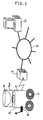
The video sensor device 11 is configured to move in a
direction perpendicular to the direction of an optical axis
of a television camera 15 while mounting a mirror 14 and the
television camera 15 on a traveling device 17. In this
explanation, the traveling device 17 moves on a horizontal
plane.
The television camera 15 is installed in such a manner
that the optical axis extends in a vertical direction, to
pick up an image reflected by the mirror 14. The mirror 14
is installed in such a manner that the optical axis of the
television camera 15 aligns with the center axis of the mirror
14 so that the image reflected by the mirror 14 can be picked
up to obtain an omnidirectional image around the optical axis
of the television camera 15 at one time.
Specifically, the mirror 14 is a curved surface that is
symmetrical with respect to the axis. It may be shaped into
a cone or a spherical surface but will be described as having
a hyperboloid. Reference numeral 14a denotes a cylindrical
translucent body for supporting the mirror 14 at a target
position. In this embodiment, however, a method for picking
up an image extending around a view point position through
360° using the mirror 14, but for example, a fisheye lens may
be used for image pickup or the camera may be rotated to
synthesize picked-up images, as long as the image can be
arranged around the view point position through 360°.
Additionally, in the following description, the video
sensor device 11 is used outdoors.
During outdoor image pickup, brightness is not uniform
in all directions, so that the user often fails to pick up
appropriate omnidirectional images with a fixed exposure.
Thus, the television camera 15 can desirably obtain
dynamic-range images that are larger than those obtained by
normal cameras; a preferable television camera can synthesize
images obtained with a normal exposure and a short-time
exposure, into one field.
The video sensor device 11 has a GPS device 16 mounted
thereon as the image pickup position obtaining means 2, to
obtain global positions of the video sensor device 11. The
GPS device 16 obtains its own position on the earth (latitude
and longitude) via a satellite (not shown). A preferable GPS
is a differential one that can obtain its own position by
detecting its relative position to a certain point the
latitude and longitude of which are known.
First, an omnidirectional image picked up by the video
sensor device 11 will be explained with reference to FIGS.
3 and 4.
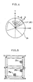
FIG. 3 is a view useful in explaining the principle of
image pickup of an omnidirectional image. Reference numeral
18 denotes a photographing object. Reference numeral 19
denotes an image forming plane of the television camera 15.
Reference numeral 20 is a focal point of the television camera
15. Reference numeral 21 denotes a position on the image
forming plane 19 where the photographing object 18 is formed
into an image. Reference numeral 22 denotes an area of the
formed image obtained by image pickup in all directions.
Coordinate axes X and Y are set on a plane parallel with
the image forming plane 19 using a focal point 20 of the
television camera 20 as an origin. In addition, a Z axis is
set in a direction perpendicular to the image forming plane
19 using the focal point 20 of the television camera 15 as
an origin. The center axis of the mirror 14 aligns with the
Z axis. In this case, an image of the photographing object
18 has its direction changed by the mirror 14 and passes
through the focal point 20 of the television camera before
reaching an image forming position 21 on the image forming
plane 19.
Since the mirror 14 is shaped into a hyperboloid, an
extension of a beam directed from the photographing object
18 to the mirror 14 always passe through a point 23 on the
Z axis despite a change in the position of the photographing
object. Reference numeral 23 is referred to as a "virtual
focal point".
Thus, the formed image 22 corresponds to an image
observed from the virtual focal point 23 through an azimuth
of 360° around the X axis. An elevation direction at the
virtual focal point 23 from an XY plane varies depending on
the angle of view of the television camera 15.
In this manner, images observed through 360° around the
Z axis in the azimuth direction and at a predetermined
elevation direction are formed in the area 22 of the formed
image at one time. The circular formed image thus obtained
is referred to as an "omnidirectional image".
An example of an omnidirectional image is shown in FIG.
4.
Reference numeral 24 denotes an omnidirectional image
that is circular. In this case, when a radial direction of
the omnidirectional image 24 is denoted by R and its
circumferential direction is denoted by , the radial
direction R corresponds to the direction of the elevation
angle of the line of sight from the virtual focal point 23
in FIG. 3, and the circumferential direction corresponds
to the direction of the azimuth of the line of sight from
the virtual focal point 23 in FIG. 3.
Next, a method for obtaining an image and positional
information stored in the omnidirectional image position
storage means 3 and how the image and the information are
recorded therein will be described with reference to FIGS.
5 and 6.
FIG. 5 is an image showing a traveling path of the video
sensor device 11. The arrow shows a traveling direction,
indicating that the device starts from point A and moves in
the order of A, B, C, D, E, F, C, D, and A. Reference numerals
25a, 25b, and 25c denote the positions of buildings located
on the path.
While moving along the traveling path shown in FIG. 5,
the video sensor device 11 uses the television camera 15 and
the GPS device 16 mounted thereon to obtain an omnidirectional
image and positional information and then transmits them to
the supply center 12. The transmission of the
omnidirectional image and positional information from the
video sensor device 11 to the supply center 12 can be
implemented by using radio or wired communication or
recording them on a recording medium such as a DVD.
FIG. 6 is a schematic view showing how omnidirectional
images and positions are recorded in the supply center 12.
In FIG. 6, reference numeral 26 denotes an
omnidirectional image position file in which are recorded
omnidirectional images photographed at the same time and
their positions which are allocated with record numbers. For
explanation, the case where the omnidirectional image and
positional information are recorded together is shown, but
they may be individually recorded and have the same record
number attached thereto.
At an arbitrary point of time after the omnidirectional
image and the positional information have been recorded in
the omnidirectional image position storage means 3, the
bidirectional communication means 10 starts communication
between the supply center 12 and the terminal device 13 in
response to a command from the terminal device 13.
Operational steps executed by the omnidirectional video
device after start of communication will be explained below
with reference to FIGS. 7 to 12.
(Step 1-1)
The omnidirectional image position storage means 3 has
the omnidirectional image position file 26 recorded therein
as shown in FIG. 6. First, positional information and a
record number are obtained, and all image pickup positions
are displayed on the image pickup position display means 4
of the terminal device 13 via the bidirectional communication
means 10.
FIG. 7 shows all image pickup positions displayed on the
image pickup position display means 4. Dotted lines in FIG.
7 show the image pickup position.
Since the positional information is provided as latitude
and longitude information obtained by the GPS device 16, the
image pickup position display means 4 displays the latitude
and longitude information on a reduced scale. Characters
A, B, C, D, E, and F in FIG. 7 indicating positions are for
explanation only and are not displayed on the image pickup
position display means 4.
(Step 1-2)
The user, who has checked all the image pickup positions
displayed on the image pickup position display means 4 at
(step 1-1), specifies the user's desired observation path
from all the image pickup positions using the view point
position indicating means 5. FIG. 8 shows a result of the
indication of the observation path using the view point
position indicating means 5. This figure shows, for example,
a result of the indication of a path passing through the points
A, B, C, and D. In this embodiment, the continuous
observation path is selected using the view point position
indicating means 5, but a discontinuous observation path such
as A-B and E-F may be selected.
Specific examples of the image pickup position display
means 4 and the view point position indicating means 5 will
be described. The terminal device 13 recognizes all the
image pickup positions and displays them on a display screen
of the terminal device 13 in the format shown in FIG. 7. The
user uses as an input device a touch panel mounted in such
a manner as to overlap the display screen, to touch via the
touch panel the display screen of all the image pickup
positions at positions corresponding to the observation path,
thereby inputting the indicated positions. Alternatively,
the user inputs the observation path from a keyboard of the
terminal device 13.
(Step 1-3)
Record numbers corresponding to the positions of the
observation path indicated by the view point position
indicating means 5 at (Step 1-2) are arranged in the order
of observation and then transmitted to the image converting
means 6 via the bidirectional communication means 10.
(Step 1-4)
Omnidirectional images corresponding to the record
numbers transmitted from the view point position indicating
means 5 at (Step 1-3) are invoked from the omnidirectional
image position storage means 3 and transmitted to the image
converting means 6.
(Step 1-5)
The omnidirectional images transmitted to the image
converging means 6 at (Step 1-4) are converted. The process
method executed by the image converting means 6 will be
explained with reference to FIGS. 3, 4, 9, and 10.
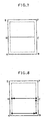
FIG. 9 shows an image into which the omnidirectional
image 24 in FIG. 4 has been converted and which is assumed
to be observed from the virtual focal point 23 shown in FIG.
3. This image is hereafter referred to as a "expanded image
27".
An X direction of the expanded image 27 corresponds to
an azimuth direction around the Z axis observed from the
virtual focal point 23, thereby allowing an image extending
through an azimuth of 360° to be obtained. In addition, a
Y direction of the image corresponds to the elevation
direction R observed from the virtual focal point 23.
Accordingly, when an arbitrary point (R1, 1) in the
omnidirectional image 24 in FIG. 4 is converted into a
position of coordinates (x1, y1) in the expanded image 27,
the following equation is established.
(x1, y1) = F (r1, 1)
A function F is a coordinate converting function and is well
known, so detailed description thereof is omitted.
At (Step 1-4), the image converting means 6 invokes the
omnidirectional images 24 corresponding to the record numbers
transmitted from the view point position indicating means
5 and converts them into the expanded images 27. The image
converting means 6 then rearranges the expanded images 27
in the order of the observation path specified by the view
point position indicating means 5.
FIG. 10 shows a sequence of the expanded images 27 thus
obtained. As shown in this figure, a expanded image file 28
having the expanded images 27 arranged in the order of the
observation is created and transmitted to the image
processing means 8 via the bidirectional communication means
10.
(Step 1-6)
The process method executed by the line-of-sight
indicating means 7 and the image processing means 8 will be
explained with reference to FIGS. 10, 11, and 12.
FIG. 11 shows an example of an image obtained by the image
processing means 8 by cutting a partial area out from the
expanded image 27 in FIG. 9. This image is hereafter referred
to as a "window image 29".
The window image 29 in FIG. 11 is obtained by specifying
a line-of-sight direction, that is, an elevation angle and
an azimuth and cutting the partial area out from the expanded
image 27 in FIG. 9. The size of the cut-out area corresponds
to the angle of view from the observation point.
(Step 1-6) will be explained below in detail.
(Step 1-6-(1))
First, the image processing means 8 uses preset
predetermined elevation angle and azimuth to create a first
window image 29 from the expanded image file 28 in FIG. 10
transmitted via the bidirectional communication means 10 at
(step 1-5), and then displays this window image on the image
display means 9. FIG. 12 is a schematic view of the sight
indicating means 7.
(Step 1-6-(2))
Then, the user uses the line-of-sight indicating means
7 to change the line-of-sight direction and the angle of view
for the image displayed on the image display means 9. FIG.
12 is a schematic view of the sight indicating means 7.
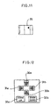
In FIG. 12, reference numerals 30a and 30b denote
elevation angle indicating buttons, reference numerals 31a
and 31b denote azimuth indicating buttons, and 32a and 32b
denote angle of view indicating buttons. These are displayed
on the image display means 9 and operated by the user using
a mouse or the like. In addition, they may be implemented
by allocating corresponding functions to ten keys of the
keyboard.
(Step 1-6-(3))
Next, the line-of-sight direction and angle of view
changed by the line-of-sight indicating means 7 are
transmitted to the image processing means 8, and the cut-out
area is changed for the next expanded image to create the
window image 29, which is then displayed on the image display
means 9. Then, (Step 1-6-(2)) and (step 1-6-(3)) are
repeated until all the expanded images 27 in the expanded
image file 28 have been processed.
As described above, according to this embodiment, the
positions at which the omnidirectional image 24 was
photographed are presented to the user beforehand so that
an image free from information on unwanted paths and
containing only a required view point position can be created
and transmitted. Consequently, the images of all the
photographed areas need not be transmitted to thereby reduce
the amount of communicated data and thus communication costs.
Additionally, the user can display images promptly to reduce
the amount of waiting time.
(Embodiment 2)
FIGS. 13 and 14 show (Embodiment 2).
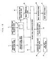
FIG. 13 shows an omnidirectional video apparatus
according to (Embodiment 2). The omnidirectional image
pickup means 1, the image pickup position obtaining means
2, the omnidirectional image position storage means 3, and
the image pickup position display means 4 are the same as
those of (Embodiment 1).
In (Embodiment 1), the terminal device 13 inputs a
desired view point and then processes data received from the
supply center 12 depending on its desired line of sight to
obtain a target display screen. (Embodiment 2) differs from
(Embodiment 1) in that not only the desired view point but
also a line-of-sight direction are specified and communicated
to the supply center 12 to obtain the target display screen
without the need to reprocess data returned to the terminal
device 13 from the supply center 12.
A line-of-sight vector indicating means 33 provided in
the terminal device 13 similarly to the image pickup position
display means 4 specifies user's desired view point position
and line-of-sight direction for an image pickup position
displayed by the image pickup position display means 4. An
output from the line-of-sight vector indicating means 33 is
input to an image extracting and converting means 34 via the
bidirectional communication means 10.
The image extracting and converting means 34 provided
in the supply center 12 invokes the omnidirectional image
24 from the omnidirectional image position file 26 of the
omnidirectional image position storage means 3, the
omnidirectional image 24 having been recorded at the view
point position indicated by the line-of-sight vector
indicating means 33. The image extracting and converting
means 34 then generates the window image 29 photographed in
the line-of-sight direction indicated by the line-of-sight
vector indicating means 33.
A sequence of the window images 29 created by the image
extracting and converting means 34 are compressed by the image
compressing means 35 and transmitted via the bidirectional
communication means 10 to the terminal device 13, where an
image recovering means 36 recovers the signal transmitted
from the image compressing means 35.
The sequence of images recovered by the image recovering
means 36 are displayed on the image display means 9.
(Embodiment 2) differs from (Embodiment 1) in that the
supply center 12 has the omnidirectional image position
storage means 3, the image extracting and converting means
34, and the image compressing means 35 and in that the terminal
device 13 has the image pickup position display means 4, the
line-of-sight vector indicating means 33, the image
recovering means 36, and the image display means 9.
The operational steps executed by the omnidirectional
video apparatus after communication has been started will
be explained.
(Step 2-1)
The omnidirectional image position storage means 3 has
the omnidirectional image position file 26 shown in FIG. 6,
recorded therein. First, positional information and record
numbers are taken out from the storage means, and the image
pickup positions are displayed on the image pickup position
display means 4 of the terminal device 13 via the
bidirectional communication means 10. The image pickup
positions displayed by the image pickup position display
means 4 are similar to those in FIG. 7.
(Step 2-2)
On checking the image pickup positions displayed on the
image pickup position display means 4 at (step 2-1), the user
specifies his or her desired observation path and line-of-sight
directions for each observation path, from all the
image pickup positions, using the line-of-sight vector
indicating means 33. FIG. 14 shows the observation path and
line-of-sight directions indicated using the line-of-sight
vector indicating means 33. The observation path is shown
by solid arrows 41, and the line-of-sight directions are
denoted by thick white arrows 42. Specifically, the
indication of the observation path is input from the display
screen or keyboard (not shown) of the terminal device 13 in
the same manner as in (Embodiment 1).
(Step 2-3)
The observation path and line-of-sight directions
indicated by the line-of-sight vector indicating means 33,
that is, the elevation angle and the azimuth are transmitted
to the image extracting and converting means 34 via the
bidirectional communication means 10.
(Step 2-4)
The image extracting and converting means 34 invokes the
omnidirectional image 24 from the omnidirectional image
position storage means 3, the omnidirectional image 24
corresponding to the observation path transmitted from the
line-of-sight vector indicating means 33.
(Step 2-5)
The image extracting and converting means 34 uses the
omnidirectional image 24 obtained at (Step 2-4) and the
line-of-sight directions obtained at (Step 2-3) to create
the window images 29 shown in FIG. 11. In this case, the
expanded images 27 shown in FIG. 9 need not necessarily be
created but the window images 29 are desirably created
directly from the omnidirectional images 24.
The created window images 29 are rearranged along the
observation path and then transmitted to the image
compressing means 35.
(Step 2-6)
The image compressing means 35 compresses the sequence
of the window images 29 obtained at (Step 2-5) to reduce the
amount of signals. Since the window images 29 have been
rearranged in the order of the observation path, for example,
the order of display, the image compression may be video
compression, for example, that based on the MPEG. The
compressed signal is transmitted to the image recovering
means 36 of the terminal device 13 via the bidirectional
communication means 10.
(Step 2-7)
The image recovering means 36 stores the images
transmitted from the image compressing means 35 in a primary
buffer (not shown) and recovers and transmits them to the
image display means 9 for display.
Thus, according to (Embodiment 2), only images required
for display can be transmitted by previously presenting the
user the positions at which the omnidirectional images 24
were photographed so that the user can indicate required view
point position and line-of-sight direction which are free
from information on unwanted paths.
Further, the images are compressed before transmission
to reduce the amount of communicated data.
In addition, the user (the terminal device 13) must
execute only the process of recovering the images and need
not execute conversions based on an image converting process,
so that the images are displayed at equal time intervals to
provide the user with the feeling of being at the site without
compromising smooth display or reproduction.
(Embodiment 3)
FIGS. 15 to 17 show (Embodiment 3).
FIG. 15 shows an omnidirectional video apparatus
according to (Embodiment 3).
(Embodiment 3) is the same as (Embodiment 2) except that
the image pickup position display means 4 of the terminal
device 13 is replaced with a map data storage means 37 and
a synthesizing position display means 38.
The map data storage means 37 according to (Embodiment
3) has map data for an area photographed by the
omnidirectional image pickup means 1, previously written
thereto. The synthesizing position display means 38 is
connected to the omnidirectional image position storage means
3 of the supply center 12 via the bidirectional communication
means 10 to display the photographing positions stored in
the omnidirectional image position storage means 3 as in
(Embodiment 1) and (Embodiment 2), while synthesizing and
displaying the map information stored in the map data storage
means 37, on the same screen.
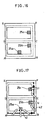
FIG. 16 shows a display format for the synthesizing
position display means 38. As also shown in FIG. 5, reference
numerals 25a, 25b, and 25c denote the positions of the
buildings on the path. In this manner, not only the traveling
path is displayed but also the map information such as the
locations of buildings are added and displayed based on the
map data.
FIG. 17 shows an observation path and a line-of-sight
direction indicated by the view point vector indicating means
33. The arrows 41 in FIG. 17 denote the observation path,
and the thick white arrows 42 denote the line-of-sight
directions. If, for example, the user desires to observe the
buildings 25a, 25b, and 25c, since their positions have been
confirmed in advance, the user selects an observation path
passing through the points A, B, C, and F and indicates the
line-of-sight directions toward the buildings 25a, 25b, and
25c.
According to (Embodiment 3), the positions where the
omnidirectional images were photographed and the map
information are synthesized and displayed to enable the user
to recognize environments of the photographing positions
beforehand to accurately indicate an observation path and
a line-of-sight direction depending on the user's tastes.
In this embodiment, the map data storage means 37 is
provided inside the terminal device 13, but similar effects
are clearly obtained by providing it inside the supply center
12 or invoking the map data storage means 37 installed in
another device (not shown) connected to the bidirectional
communication device.
(Embodiment 4)
FIGS. 18 to 20 shows (Embodiment 4).
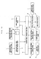
(Embodiment 4) is the same as (Embodiment 1) except that
the map data storage means 37 and the synthesizing position
display means 38 replace the image pickup position display
means 4 according to (Embodiment 1) shown in FIG. 1 and that
an object specifying means 39 and a view point position
computing means 40 replace the view point position indicating
means 5. The map data storage means 37 and the synthesizing
position display means 38 are the same as those in (Embodiment
3).
The object specifying means 39 is an input device for
specifying only a desired object of the objects on all the
image pickup paths displayed by the synthesizing position
display means 38.
A view point position computing means 40 computes an
optimal path from the position of the object specified by
the object specifying means 39.
(Step 4-1)
On receiving positional information and record numbers
from the omnidirectional image position storage means 3 via
the bidirectional communication means 10, the synthesizing
position display means 38 invokes from the map data storage
means 37 map data for an area photographed by the
omnidirectional image pickup means 1, and synthesizes and
displays them.
A path diagram displayed by the synthesizing position
display means 38 and having the additional map data is similar
to that in FIG. 16. As also shown in FIG. 5, reference
numerals 25a, 25b, and 25c denote the positions of the
buildings on the path. In this manner, not only the traveling
path is displayed but also the map information such as the
locations of buildings are added and displayed based on the
map data.
(Step 4-2-(1))
On checking all the photographing positions displayed
on the synthesizing position display means 38 at (Step 4-1),
the user uses the object specifying means 39 to specify only
a desired object on the path of the photographing positions
displayed on the synthesizing position display means 38.
FIG. 19 shows a result of specification of a plurality
of objects by means of the object specifying means 39. The
thick white arrows denote the specified objects; in FIG. 19,
the buildings 25a and 25c have been specified.
(Step 4-2-(2))
The view point position computing means 40 in FIG. 18
automatically computes a path for observing the specified
buildings 25a and 25c as shown in FIG. 19.
FIG. 20 shows a result of display of the result of the
computation of the observation path. The path is shown by
an arrow 44. To compute the path, for example, all paths
joining the buildings 25a and 25c in FIG. 19 together and
the shortest of them is determined as the observation path.
A different method may be used to compute the path as long
as it can compute a path between a plurality of objects.
Since the observation path has been established at (Step
4-2-(2)), the subsequent steps are similar to (step 1-3) to
(Step 1-6) in (Embodiment 1).
According to (Embodiment 4), the positions where the
omnidirectional images 24 were photographed and the map
information are synthesized and displayed to enable the user
to recognize environments of the photographing positions
beforehand to accurately indicate an observation path
depending on the user's tastes. In addition, the path can
be automatically created simply by specifying the user's
desired place, so that images of the user's desired place
can be simply reproduced without the need to input the view
point position.
In this embodiment, the observation path is
automatically computed while the line-of-sight direction is
indicated by the user, but the direction of the object
relative to the observation path can be easily estimated from
this path. Thus, the view point position computing means 40
can be used to mathematically obtain the observation path
and the line-of-sight direction. In that case, the process
will be similar to (Step 2-3) and (Step 2-7) in (Embodiment
2).
Specifically, the terminal device 13 has an computation
means for computing an optimal observation path joining each
view point with the position of the object specified by the
object specifying means 39 to output view point information
and estimating the direction of the object relative to the
observation path to output line-of-sight information. The
supply center 12 has the image extracting and converting means
34 for invoking required image data from the omnidirectional
image position storage means 3 to convert them into expanded
images based on the view point information and line-of-sight
information indicated by the computation means via the
bidirectional communication means 10, and processing the
expanded images 27 depending on the line-of-sight information.
The terminal device 13 has the image display means 9 for
displaying as an image a signal received from the image
extracting and converting means 34 via the bidirectional
communication means 10.