JP4098808B2 - Remote video display method, video acquisition device, method thereof, and program thereof - Google Patents
Remote video display method, video acquisition device, method thereof, and program thereof Download PDFInfo
- Publication number
- JP4098808B2 JP4098808B2 JP2005507676A JP2005507676A JP4098808B2 JP 4098808 B2 JP4098808 B2 JP 4098808B2 JP 2005507676 A JP2005507676 A JP 2005507676A JP 2005507676 A JP2005507676 A JP 2005507676A JP 4098808 B2 JP4098808 B2 JP 4098808B2
- Authority
- JP
- Japan
- Prior art keywords
- signal
- video
- camera
- acquisition
- information
- Prior art date
- Legal status (The legal status is an assumption and is not a legal conclusion. Google has not performed a legal analysis and makes no representation as to the accuracy of the status listed.)
- Expired - Fee Related
Links
Images


Classifications
-
- H—ELECTRICITY
- H04—ELECTRIC COMMUNICATION TECHNIQUE
- H04N—PICTORIAL COMMUNICATION, e.g. TELEVISION
- H04N7/00—Television systems
- H04N7/18—Closed-circuit television [CCTV] systems, i.e. systems in which the video signal is not broadcast
- H04N7/183—Closed-circuit television [CCTV] systems, i.e. systems in which the video signal is not broadcast for receiving images from a single remote source
- H04N7/185—Closed-circuit television [CCTV] systems, i.e. systems in which the video signal is not broadcast for receiving images from a single remote source from a mobile camera, e.g. for remote control
-
- H—ELECTRICITY
- H04—ELECTRIC COMMUNICATION TECHNIQUE
- H04N—PICTORIAL COMMUNICATION, e.g. TELEVISION
- H04N21/00—Selective content distribution, e.g. interactive television or video on demand [VOD]
- H04N21/20—Servers specifically adapted for the distribution of content, e.g. VOD servers; Operations thereof
- H04N21/21—Server components or server architectures
- H04N21/218—Source of audio or video content, e.g. local disk arrays
- H04N21/21805—Source of audio or video content, e.g. local disk arrays enabling multiple viewpoints, e.g. using a plurality of cameras
-
- H—ELECTRICITY
- H04—ELECTRIC COMMUNICATION TECHNIQUE
- H04N—PICTORIAL COMMUNICATION, e.g. TELEVISION
- H04N21/00—Selective content distribution, e.g. interactive television or video on demand [VOD]
- H04N21/40—Client devices specifically adapted for the reception of or interaction with content, e.g. set-top-box [STB]; Operations thereof
- H04N21/41—Structure of client; Structure of client peripherals
- H04N21/422—Input-only peripherals, i.e. input devices connected to specially adapted client devices, e.g. global positioning system [GPS]
- H04N21/4223—Cameras
-
- H—ELECTRICITY
- H04—ELECTRIC COMMUNICATION TECHNIQUE
- H04N—PICTORIAL COMMUNICATION, e.g. TELEVISION
- H04N21/00—Selective content distribution, e.g. interactive television or video on demand [VOD]
- H04N21/60—Network structure or processes for video distribution between server and client or between remote clients; Control signalling between clients, server and network components; Transmission of management data between server and client, e.g. sending from server to client commands for recording incoming content stream; Communication details between server and client
- H04N21/65—Transmission of management data between client and server
- H04N21/658—Transmission by the client directed to the server
- H04N21/6587—Control parameters, e.g. trick play commands, viewpoint selection
-
- H—ELECTRICITY
- H04—ELECTRIC COMMUNICATION TECHNIQUE
- H04N—PICTORIAL COMMUNICATION, e.g. TELEVISION
- H04N23/00—Cameras or camera modules comprising electronic image sensors; Control thereof
- H04N23/60—Control of cameras or camera modules
- H04N23/63—Control of cameras or camera modules by using electronic viewfinders
-
- H—ELECTRICITY
- H04—ELECTRIC COMMUNICATION TECHNIQUE
- H04N—PICTORIAL COMMUNICATION, e.g. TELEVISION
- H04N23/00—Cameras or camera modules comprising electronic image sensors; Control thereof
- H04N23/60—Control of cameras or camera modules
- H04N23/66—Remote control of cameras or camera parts, e.g. by remote control devices
- H04N23/661—Transmitting camera control signals through networks, e.g. control via the Internet
-
- H—ELECTRICITY
- H04—ELECTRIC COMMUNICATION TECHNIQUE
- H04N—PICTORIAL COMMUNICATION, e.g. TELEVISION
- H04N23/00—Cameras or camera modules comprising electronic image sensors; Control thereof
- H04N23/60—Control of cameras or camera modules
- H04N23/698—Control of cameras or camera modules for achieving an enlarged field of view, e.g. panoramic image capture
-
- H—ELECTRICITY
- H04—ELECTRIC COMMUNICATION TECHNIQUE
- H04N—PICTORIAL COMMUNICATION, e.g. TELEVISION
- H04N7/00—Television systems
- H04N7/18—Closed-circuit television [CCTV] systems, i.e. systems in which the video signal is not broadcast
- H04N7/181—Closed-circuit television [CCTV] systems, i.e. systems in which the video signal is not broadcast for receiving images from a plurality of remote sources
Description
この発明はパノラマ被写体を、画像センサ、つまり映像信号を出力するカメラ(以下、単にカメラと記載する)で撮影して、その撮影映像を前記カメラから離れた場所の利用者に表示する遠隔映像表示方法、その方法に用いられる映像取得装置、その映像取得方法、及び映像取得プログラムに関する。 The present invention captures a panoramic subject with an image sensor, that is, a camera that outputs a video signal (hereinafter simply referred to as a camera), and displays the captured video for a user away from the camera. The present invention relates to a method, a video acquisition device used in the method, a video acquisition method thereof, and a video acquisition program.
例えば道路の交通量を把握するために、監視用カメラを雲台上に取付けて、道路の交通状態を撮影できるように設置し、このカメラよりの映像信号を通信回線を通じて遠隔地に設置された監視装置へ伝送し、監視装置では受信した映像信号を再生して表示器に、監視カメラが撮影した道路の交通状態を表示し、監視員はその表示を見ながら遠隔制御装置の操作釦やレバーなどを操作して、監視用カメラの撮影方向(水平方向及び垂直方向)を変更する制御信号、又は/及び監視用カメラのズームレンズのズーム量を変更する制御信号を通信回線を通じて監視用カメラの制御機構部に伝送して、監視用カメラを制御し、表示器に表示される映像を見ながら監視用カメラの撮影方向や撮影状態を制御することが行われている(特許文献1参照)。 For example, in order to grasp the traffic volume on the road, a monitoring camera was installed on the camera platform so that the traffic state of the road could be photographed, and the video signal from this camera was installed at a remote location via a communication line. The monitoring device reproduces the received video signal and displays the traffic state of the road photographed by the monitoring camera on the display, and the monitor looks at the display and the operation buttons and levers of the remote control device The control signal for changing the shooting direction (horizontal direction and vertical direction) of the monitoring camera or / and the control signal for changing the zoom amount of the zoom lens of the monitoring camera are transmitted via the communication line to the monitoring camera. It is transmitted to the control mechanism unit to control the monitoring camera, and the shooting direction and shooting state of the monitoring camera are controlled while viewing the video displayed on the display (see Patent Document 1).
高層建築の屋上に雲台上に取付けたカメラを設置し、インターネットなどの通信網を通じて、パーソナルコンピュータからカメラをアクセスして、予め決められた時間、そのカメラを占有し、そのカメラの撮影映像信号をパーソナルコンピュータに受信してその表示器に再生表示し、利用者はその再生映像を見ながら、パーソナルコンピュータを操作して、カメラの撮影方向やレンズのズーム量を遠隔制御して、広い範囲のパノラマ被写体の各部分を見て楽しむサービス、いわゆるビデオライブが提供されている。 A camera mounted on a pan head is installed on the rooftop of a high-rise building, and the camera is accessed from a personal computer through a communication network such as the Internet, and the camera is occupied for a predetermined time. Is displayed on the display and displayed on the display, and the user operates the personal computer while viewing the playback video to remotely control the shooting direction of the camera and the zoom amount of the lens. Services that allow you to enjoy watching each part of a panoramic subject, so-called video live, are provided.
親が自宅あるいは、勤務先からパーソナルコンピュータを制御して、通信回線を介して幼稚園に設けたカメラをアクセスしてその撮影映像信号をパーソナルコンピュータに再生表示し、カメラの撮影方向やズーム量を遠隔制御して各種状態での子供の様子を知ることが考えられる。
更にコンビニエンスストアに設けた防犯カメラの撮影映像信号を離れた所で表示器に再生表示すると共に、守備員はその再生映像を見ながら防犯カメラの撮影方向やズーム量を遠隔制御することが考えられる。
The parent controls the personal computer from home or work, accesses the camera set up in the kindergarten via the communication line, reproduces and displays the captured video signal on the personal computer, and remotely controls the shooting direction and zoom amount of the camera. It can be considered to know the state of the child in various states by controlling.
Furthermore, it is possible that the video signal of the security camera provided at the convenience store is reproduced and displayed on the display at a distance, and the guards can remotely control the shooting direction and zoom amount of the security camera while viewing the reproduced video. .
このように遠方に設けられたカメラを遠隔制御してその撮影映像信号を表示させることは各種の利用が考えられる。いずれの場合も、従来においては、カメラ自体の撮影方向を機械的に変更制御し、あるいはズームレンズを機械的に移動させる制御を、パーソナルコンピュータを利用したボタン(キー)操作やレバー操作により行われるものであった。また、1人の利用者がカメラを遠隔制御している間は、他の利用者はそのカメラを制御できず、つまり、例えば予め決められた時間、そのカメラは1人の利用者により占有されるものである。
従来の遠隔映像表示における見たい映像を得るための制御はボタン(キー)操作、あるいはレバー操作によりカメラ自体を遠隔制御するものであるため、利用者がカメラを直接手で持って、あるいは雲台上のカメラを直接手で操作して所望の撮影映像を得る場合と比較して、操作性が悪く、つまり所望の撮影映像と多少ずれたものとなる場合があった。 In conventional remote image display, the control for obtaining the desired image is to remotely control the camera itself by button (key) operation or lever operation, so the user can hold the camera directly by hand or use the pan head. Compared with the case where a desired photographed image is obtained by directly operating the upper camera by hand, there are cases where the operability is poor, that is, the image is slightly deviated from the desired photographed image.
この発明の目的は、利用者がその手でカメラを直接操作する感覚で所望の遠隔映像を表示させることを可能とする遠隔映像表示方法、その方法に用いられる映像取得装置、その方法、及び映像取得プログラムを提供することにある。 An object of the present invention is to provide a remote image display method that enables a user to display a desired remote image with the feeling that a user directly operates a camera with his hand, an image acquisition device used in the method, an image method, and an image To provide an acquisition program.
この発明の遠隔映像表示方法によれば、パノラマ被写体を遠隔撮影装置で撮影し、その撮影したパノラマ被写体の一部分の撮影映像信号を映像取得装置を介して、遠隔撮影装置と、異なる位置の映像表示手段に送信し、映像表示手段は受信した撮影信号を再生してパノラマ被写体の上記一部分の映像として表示し、
その映像表示手段の表示を見ることができる位置のカメラ付携帯端末により、その周辺を撮影し、その周辺映像信号を映像取得装置へ送信し、
映像取得装置で、前回の受信周辺映像信号と今回の受信周辺映像信号とから、カメラ付携帯端末が撮影した周辺映像の変化情報を求め、この変化情報に基づき、撮影した周辺映像の変化と対応して、パノラマ被写体の一部分に対して変更されたパノラマ被写体の一部分の撮影映像信号を遠隔撮影装置から求め、その求めた撮影映像信号を映像表示手段へ送信する。
According to the remote image display method of the present invention, a panoramic subject is photographed by a remote photographing device, and a photographed video signal of a part of the panoramic subject photographed is displayed at a position different from that of the remote photographing device via the video acquisition device. And the video display means reproduces the received shooting signal and displays it as a video of the part of the panoramic subject,
With the camera-equipped mobile terminal at the position where the display of the video display means can be seen, the periphery is photographed and the peripheral video signal is transmitted to the video acquisition device.
The video acquisition device obtains the change information of the surrounding video captured by the camera-equipped mobile terminal from the previous received peripheral video signal and the current received peripheral video signal, and responds to the change of the captured peripheral video based on this change information. Then, a photographic video signal of a part of the panoramic subject changed with respect to a part of the panoramic subject is obtained from the remote photographing device, and the obtained photographic video signal is transmitted to the video display means.
パノラマ被写体は、映像表示手段の一表示画面分の映像として表示するには適さない程度に十分広い、あるいは一表示画面分の映像としてある程度の表示はできるがその各一部分の詳細を見る必要がある視野範囲の大きさであり、視野角は360度かそれ以下であり、また必ずしも連続していなくてもよい。映像取得装置がパノラマ被写体の変更された一部分の撮影映像信号を遠隔撮影装置から求めるのは、二つの形態がある。その一つの形態によれば、カメラ付携帯端末から受信した前回の周辺映像信号の映像(以下、前回映像と記述する)に対する今回の周辺映像信号の映像(以下、今回映像と記述する)の変化情報が、変化検出手段により受信周辺映像信号から検出され、その変化情報とから、パノラマ被写体の一部分の撮影映像信号を得るために用いる取得用信号が取得用信号生成手段により生成され、その生成された取得用信号が遠隔撮影装置へ送信され、遠隔撮影装置より受信された撮影映像信号が映像中継手段により、映像表示手段へ送信される。この形態では映像取得装置は取得用信号を遠隔撮影装置へ送り、遠隔撮影装置がパノラマ被写体の変更された一部分の撮影映像信号を取り出し送信した映像信号を受信することにより、パノラマ被写体の変更された一部分の撮影映像信号を求める。 The panorama subject is wide enough to be unsuitable for displaying as one display screen image of the image display means, or can be displayed to some extent as one display screen image, but it is necessary to see the details of each part thereof It is the size of the viewing range, the viewing angle is 360 degrees or less, and does not necessarily have to be continuous. There are two forms in which the video acquisition device obtains a part of the panoramic subject's changed video image signal from the remote imaging device. According to one embodiment, the video of the current peripheral video signal (hereinafter referred to as the current video) relative to the video of the previous peripheral video signal (hereinafter referred to as the previous video) received from the camera-equipped mobile terminal is changed. Information is detected from the received peripheral video signal by the change detection means, and from the change information, an acquisition signal used for obtaining a captured video signal of a part of the panoramic subject is generated by the acquisition signal generation means and generated. The acquisition signal is transmitted to the remote photographing apparatus, and the photographed video signal received from the remote photographing apparatus is transmitted to the video display means by the video relay means. In this mode, the video acquisition device sends the acquisition signal to the remote imaging device, and the remote imaging device receives the video signal obtained by extracting and transmitting the portion of the panoramic subject that has been changed, thereby changing the panoramic subject. Obtain a portion of the captured video signal.
他の形態によれば、同様に変化検出手段及び取得用信号生成手段が設けられ、遠隔撮影装置より受信した撮影映像信号から生成された取得用信号に基づき、その映像取得装置の映像取得手段によりパノラマ被写体の変更された一部分の撮影映像信号が取り出されて求められる。 According to another aspect, a change detection unit and an acquisition signal generation unit are provided in the same manner, and based on the acquisition signal generated from the captured video signal received from the remote imaging device, the video acquisition unit of the video acquisition device A captured video signal of a part of the panoramic subject that has been changed is extracted and obtained.
この発明の表示方法によれば、映像表示手段に表示されているパノラマ被写体の一部分の映像を見ながら、カメラ付携帯端末を手に持ってそのカメラ付携帯端末によりパノラマ被写体の一部を撮影するようにカメラ付携帯端末を操作することにより、パノラマ被写体の所望の部分を遠隔撮影表示することができ、パノラマ被写体を直接見ることができる場所で自分でカメラを操作して撮影する場合と、同様な感じで操作することができ操作性が頗るよく、かつパノラマ被写体の所望とする部分と撮影された映像とのずれが生じ難い。 According to the display method of the present invention, while viewing a video of a part of a panoramic subject displayed on the video display means, the mobile terminal with a camera is held and a part of the panoramic subject is photographed by the mobile terminal with the camera. By operating the camera-equipped mobile terminal as described above, it is possible to remotely shoot and display a desired portion of the panoramic subject, which is the same as when shooting by operating the camera yourself in a place where the panoramic subject can be seen directly It is easy to operate and the operability is improved, and the desired portion of the panoramic subject is not easily displaced from the captured image.
原理説明
図1を参照してこの発明の原理を説明する。
この例では遠隔撮影装置2として全方位カメラが用いられた場合である。全方位カメラはディジタルビデオカメラであって、周囲360度を撮影可能な全方位画像センサであり、例えば山澤一誠著「ミラーを用いた全方位カメラの原理と特徴」コンピュータビジョンとイメージメディア125−21、P.155〜160、2001年1月19日を参照されたい。また全方位カメラは市販されており、例えば図2に示すように予め決めた基準方向を0度とし、360度のパノラマ被写体のカメラ像がCCDなどの長方形の2次元イメージセンサデバイス7に結像され、各画素対応の光電気変換信号を取出すことができる。
Principle Description The principle of the present invention will be described with reference to FIG.
In this example, an omnidirectional camera is used as the
図1において遠隔撮影装置2はその360度にわたる周囲のパノラマ被写体6を撮影することができる。この例ではその遠隔撮影装置2で撮影したパノラマ被写体6の一部分、例えば基準に対し180度の方向の一部分(以下、部分被写体と記述する)61の撮影映像信号、つまり図2におけるイメージセンサデバイス7中の領域71の各画素信号が取り出されて伝送路4を通じて映像取得装置1へ送信される。
In FIG. 1, the
映像取得装置1では受信した部分被写体の撮影映像信号を伝送路5を通じて、遠隔撮影装置2とは異なる位置の映像表示手段を兼ねるカメラ付携帯端末3へ送信する。カメラ付携帯端末3としてこの例ではカメラ付携帯電話機を用いているが、カメラ付PDA(Personal Digital Assistance)や、PDAにカメラを固定したものなど、要はディジタルビデオカメラを備え、かつ通信手段を備え、手に持ってカメラ撮影操作を行うことができる端末であればよい。伝送路4及び5はこれらを区別するため以下、それぞれ遠隔用伝送路4及び携帯用伝送路5と記述する。これら両伝送路4及び5はいずれも専用伝送回路であっても、インターネット、無線・有線公衆通信網などの通信網を一つ乃至複数介する伝送路であってもよい。
The
所でこの例はカメラ付携帯端末3は映像表示手段をも備えるものであり、映像取得装置1から受信した遠隔撮影装置2よりの部分被写体61の撮影映像信号はその映像表示手段により再生されて、その表示面32aに表示される。
In this example, the camera-equipped
利用者はカメラ付携帯端末3を手に持ってその端末3のカメラ(携帯撮影手段)33でその利用者の周辺被写体8を撮影しながら、表示面32aに表示されたパノラマ被写体6の部分被写体61を見て、パノラマ被写体6中の遠隔撮影表示したい他の部分被写体を見たい場合は、そのカメラ33でその見たい部分被写体を撮影するように、カメラ付携帯端末3を操作する。例えば部分被写体61に対し、右へ45度の方向の部分被写体62を撮影したい場合は、カメラ付携帯端末3で現に撮影している方向33aから、図1中に1点鎖線で示すようにカメラ付携帯端末3のカメラ33の撮影方向33aを右へ45度回転する。
The user holds the camera-equipped
カメラ付携帯端末3のカメラ33により撮影されている周辺被写体の映像信号(以後、周辺映像信号と記述する)は携帯用伝送路5を通じて映像取得装置1へ送信される。映像取得装置1は受信した前回の周辺映像信号と、今回の周辺映像信号とから、カメラ付携帯端末3が撮影している周辺映像が変化したことを検出する。
A video signal of a peripheral subject (hereinafter referred to as a peripheral video signal) captured by the
周辺被写体8に対し、カメラ付携帯端末3が撮影している範囲は図3Aに示すように撮影範囲8aに対し右側に移動した撮影範囲8bとなる。従って部分被写体61の再生映像を見た時の受信周辺映像信号は図3Bの上側に示す撮影範囲8aの撮影映像信号であるが、カメラ付携帯端末3の撮影方向が右へ45度回転された状態での受信周辺映像信号は図3Bの下側に示す撮影範囲8bの撮影映像信号となる。これら両受信周辺映像信号を比較すれば、同一の映像部分が、図において右から左へ移動しており、そのカメラ付携帯端末3の撮影方向が右へ回転されたことを検出することができる。
The range in which the camera-equipped
映像取得装置1はこの受信周辺映像信号の映像の前回のそれに対する変化情報を検出し、この変化情報に基づき遠隔撮影装置2で撮影している映像信号から取り出す撮影映像信号を変更して、その取出した撮影映像信号と対応するパノラマ被写体6中の部分被写体が、受信周辺映像信号の映像の変化に対応して変更されるように遠隔撮影装置2に指示する。カメラ付携帯端末3の撮影方向を前記例では45度右へ回転させた場合は、パノラマ被写体6の部分被写体61がその方向に対して右へ45度回転した部分被写体62と対応した撮影映像信号を取り出すように、図2中のイメージセンサデバイス7上の領域71に対し、周辺撮影映像の移動距離D1だけ右へ移動させた領域72の撮影映像信号を取り出すように、映像取得装置1は遠隔撮影装置2に遠隔用伝送路4を通じて指示する。
The
遠隔撮影装置2はこの指示を受信して、イメージセンサデバイス7の領域72から撮影映像信号を取り出して、遠隔用伝送路4を通じて映像取得装置1へ送信し、映像取得装置1はその受信撮影映像信号を携帯用伝送路5を通じてカメラ付携帯端末3へ送信する。カメラ付携帯端末3はその表示面32aに部分被写体62と対応する再生映像を表示することになる。
The remote photographing
遠隔撮影装置2はパノラマ被写体6を常時撮影し、映像取得装置1から取得指示に基づいて部分被写体の撮影映像信号を常時、例えば毎秒30フレームの速さで映像取得装置1を中継してカメラ付携帯端末3へ送信している。カメラ付携帯端末3もその撮影周辺映像信号を常時映像取得装置1へ送信している。
The remote photographing
以上の説明から理解されるようにこの発明の方法によればパノラマ被写体6を実際に見ながらその撮影表示したい部分を撮影するようにカメラ付携帯端末3を操作することにより所望の部分被写体を遠隔撮影表示することができ、遠隔撮影の操作性がよく、かつ所望の部分被写体と撮影映像信号の再生映像とのずれが生じ難いものとなる。また例えば携帯電話機のような携帯端末のキーを操作してカメラを遠隔操作することを想定すると、その場合はキーの操作であることに基づく操作性が悪い上に、キーが小さくかつ複数のキーが接近しているため誤操作をし易いが、この発明方法によればそのようなおそれもない。
As can be understood from the above description, according to the method of the present invention, a desired partial subject can be remotely controlled by operating the
実施例1
図4にこの発明の実施例1が適用されるシステム構成例を示す。なおこの出願中のすべての図において、同一参照番号は同一機能のものを表わし、重複説明を省略する。
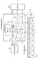
映像取得装置1はカメラ付携帯端末3から携帯用伝送路5を通じて受信される周辺映像信号を受信する周辺映像受信手段11と、受信された周辺映像信号から周辺映像信号の映像の変化を変化情報として検出する変化検出手段12と、その検出した変化情報に基づき取得用信号を生成する取得用信号生成手段13と、その生成した取得用信号を遠隔用伝送路4を通じて遠隔撮影装置2へ送信する送信手段14と、遠隔撮影装置2から遠隔用伝送路4を介して送信された撮影映像信号を受信して、携帯用伝送路5を介してカメラ付携帯端末3へ送信する映像中継手段15とを備える。
Example 1
FIG. 4 shows a system configuration example to which the first embodiment of the present invention is applied. In all the drawings in this application, the same reference numerals represent the same functions, and duplicate explanations are omitted.
The
遠隔撮影装置2はパノラマ被写体を撮影する遠隔撮影手段としての全方位カメラ21と、遠隔用伝送路4を介して映像取得装置1から送信された取得用信号を受信する信号受信手段23と、その受信した取得用信号に基づき、全方位カメラ21から部分被写体の撮影映像信号を取り出す映像取り出し手段24と、その取り出された撮影映像信号を遠隔用伝送路4を介して映像取得装置1へ送信する映像送信手段22とを備える。
The remote photographing
カメラ付携帯端末3は遠隔撮影装置2から携帯用伝送路5を介して送信された撮影映像信号を受信する映像受信手段31と、その受信した撮影映像信号を再生表示する映像表示手段32と、周辺被写体を撮影する携帯撮影手段としてのディジタルビデオカメラ33と、そのカメラ33で撮影した周辺映像信号を映像取得装置1へ携帯用伝送路5を介して送信する送信手段34とを備える。
The camera-equipped
遠隔撮影装置2の映像取り出し手段24では受信した取得用信号により決まる1画面分の撮影映像信号を全方位カメラ21から取り出す。例えば、取得用信号により図2に示すイメージセンサデバイス中における画素位置(x1,y1)を中心として各画素(x+aPi,y+aPj)(i=0,±1,…,±I、j=0,±1,…,±J、2Iは1画面相当のx方向の画素数、2Jは1画面相当のy方向の画素数)の信号を順次取り出し、領域71の撮影映像信号として出力する。つまりこの例では取得したい部分被写体の中心位置と、ズーム量が取得用信号により指定して取出される。この例では取得用信号は基準画素位置信号x、yと拡大・縮小信号aPとからなる。
The video extraction means 24 of the
この撮影映像信号が映像取得装置を介してカメラ付携帯端末3へ伝送され、カメラ付携帯端末3の映像表示手段32には、遠隔撮影装置2が撮影しているパノラマ被写体中の部分被写体、この例では図1中の部分被写体62の映像が表示される。
This photographed video signal is transmitted to the camera-equipped
映像取得装置1の変化検出手段12ではカメラ付携帯端末3から受信された前回の周辺映像信号の映像(以下、前回映像と記述する)に対する今回の周辺映像信号の映像(以下、今回映像と記述する)の変化情報を受信周辺映像信号から検出する。例えば図5に示すように周辺映像信号が受信されると、受信バッファメモリ12aに格納され、その格納の前に前回受信し受信バッファメモリ12aに格納されていた周辺映像信号は前回フレームメモリ12bに格納される。両メモリ12a及び12b内に格納されている両周辺映像信号が変化検出部12cに入力される。変化検出部12cでは前回映像から今回映像への移動方向又はこれとその移動の程度(大きさ)又は/及び前回映像に対する今回映像のオブジェクトの大きさの変化、つまりズーム量を検出する。この変化情報の検出技術は、例えば撮影中のカメラの動き、いわゆるカメラワークを解析する技術を用いることができる。カメラワークの解析技術は例えば谷口行信他著「Panorama Excerpts:パノラマ画像の自動生成・レイアウトによる映像一覧」電子情報通信学会論文誌D−II、Vol.J82−D−II No.3,PP.390−398,1999年3月や、書籍、小暮賢司監修、山森和彦著「未来ねっと技術シリーズ メディア処理技術4」20 電気通信協会 平成11年11月10日初版発行などに示されている。
In the change detection means 12 of the
例えばカメラの左右の回転(パン)操作、カメラの上下の回転(チルト)操作、カメラのレンズによる画角を変化させる(ズーム)操作のカメラワークを解析する手法の一例を述べる。前回映像をf(x,y)、今回映像をf’(x’,y’)
(x’,y’)=(ax+dx,ay+dy)
とし、つまりa,dx及びdyをそれぞれズーム、パン及びチルトを説明するパラメータとする。映像f(x,y)とf’(x’,y’)との間の2乗誤差
(1/N)Σx,y{f(x,y)−f’(x’,y’)}2
を最小化するパラメータa,dx,dyを求める。これらa,dx,dyを変化情報とする。つまり変化検出部12cでは例えばa,dx,dyを演算して変化情報とする、つまりaは拡大・縮小情報であり、dx,dyは方向情報である。カメラ付携帯端末3の左右の回転のみを検出する場合はa=1,dy=0とし、上下の回転のみを検出する場合はa=1,dx=0とし、ズーム変化のみを検出する場合はdx=dy=0、回転のみを検出する場合はa=1とすればよい。
For example, an example of a technique for analyzing camera work of a left / right rotation (pan) operation of a camera, a vertical rotation (tilt) operation of a camera, and an operation of changing a view angle by a camera lens (zoom) will be described. F (x, y) for the previous video, f '(x', y ') for the current video
(X ′, y ′) = (ax + d x , ay + d y )
And then, to that it is a, zoom d x and d y, respectively, a parameter describing the pan and tilt. Square error between video f (x, y) and f ′ (x ′, y ′) (1 / N) Σx , y {f (x, y) −f ′ (x ′, y ′) } 2
Minimizing parameters a, obtaining a d x, d y. These a, d x , and dy are used as change information. That is, in the
取得用信号生成手段13は変化検出手段12で検出された変化情報と前回取得用信号とからパノラマ被写体の部分被写体の撮影映像信号を取得するために用いる取得用信号を生成する。取得用信号生成手段13は例えば図5中に示すように、前回信号メモリ13aに前回生成され、現在用いられている取得用信号、例えばx,y,aPが格納されており、これら信号x,y,aPと、変化情報、例えばdx,dy,axが加算部13bでx+dx→x、加算部13cでy+dy→y、乗算部13dでaP×a→aPがそれぞれ演算されて補足され、新たな取得用信号が生成され、この新たな取得用信号x,y,aPで前回信号メモリ13a内の各取得用信号が更新されると共に信号送信手段14へ出力される。なお映像取得装置1による映像取得処理が行われていない状態では、前回信号メモリ13aには、予め決められた取得用信号、例えば図2中のセンサデバイス7の中心x,y、最大ズーム量の半分の値をaPが初期値として、格納されてあり、映像取得装置1が取得処理を開始すると、前回信号メモリ13a中の初期値信号x,y,aPが取得用信号として遠隔撮影装置2へ送信される。
The acquisition
また変化情報が小さい、例えばdx=1などの場合は、カメラ付携帯端末3に表示されるパノラマ被写体の部分被写体の映像はほとんど変化しないため、切捨部13e,13f,13gを設け、dx,dy,aがそれぞれに対し予め決められた所定値以下の場合はdx,dyをそれぞれ0、aを1として加算部13b,13c、乗算部13dへ供給されるようにするとよい。切捨部13e,13f,13gにそれぞれ設定する前記所定値は、各切捨部、またこの遠隔撮影表示システムを利用する形態により異なり、遠方の風景の部分被写体を遠隔撮影表示する場合は比較的大きな値とし、比較的小さい空間の防犯用に利用する場合は比較的小さな値とするなどあるが、例えばdxについてみれば最小でも5以下は0とすることが考えられる。
When the change information is small, for example, d x = 1, the partial subject image of the panoramic subject displayed on the camera-equipped
遠隔撮影装置2へ送信する取得用信号の更新は一般に各フレームの受信ごとに行うと処理が多くなり好ましくなく、また一般に各フレームごとに更新を行っても、受信部分被写体映像の変化は利用者にとってほとんど感じられない。従って遠隔撮影装置2への取得用信号の送信間隔は適当な間隔で行えばよい。この間隔は例えば交通量の監視のように被写体の状況の変化が比較的速い場合は例えば1/10秒ごとに、被写体が風景の場合は例えば1/3秒ごとに、場合によったら数秒ごとになどと、システムの利用形態に応じて適当に決められるとよい。このために例えば変化検出手段12中に更新指示部12dを設け、設定された更新時間間隔で更新指示部12dの指示により受信バッファメモリ12aに1フレーム分の周辺映像信号を取り込み、変化検出部12cでの変化情報の検出を更新時間間隔ごとに行うようにする。あるいは受信バッファメモリ12aの内容を周辺映像信号の1フレーム分ごとに更新し、変化情報の検出ごとに受信バッファメモリ12aの内容を前回フレームメモリ12bに転送してもよい。なお変化検出部12cで検出した変化情報がすべてゼロ、この例ではdx=dy=0、a=1であれば、取得用信号を生成して遠隔撮影装置へ送信する必要はなく、その場合は取得用信号の生成も行う必要はない。また取得用信号の生成、送信は、変化情報中の変化のあった情報のみについて行ってもよい。
Updating the acquisition signal to be transmitted to the
遠隔撮影装置2において、信号受信手段23で受信された取得用信号は図4中に示すように映像取り出し手段24に入力され、この取得用信号により記憶部24aに格納されている前回受信した取得用信号が更新される。映像取り出し手段24はその記憶部24aの更新された取得用信号に基づき全方位カメラ21が撮影しているパノラマ被写体中の部分被写体の撮影映像信号が取り出される。例えば全方位カメラ21のイメージセンサデバイス7から、図2に示したように更新前の取得用信号(基準画素位置信号)により画素(x,y)を中心(基準)とする一画面分の領域71の撮影映像信号が常時取り出されている状態から、更新された取得用信号(基準画素位置信号)により画素(x’,y’)を中心とする一画面分の領域72の撮影映像信号が常時取り出される状態になる。この図2に示す例では、カメラ付携帯端末3の撮影方向が上下方向及びズーム量は変化せず右方向にのみ回転した場合、つまり変化情報dy=0、a=1でdxが検出され、取得用信号がx,y,aPからx←x+dx、y’,a’P←aPとなった場合である。ここで更新された情報x,y,aPをその更新前と区別するため対応情報に対しダッシュ「’」を付けて示した。図4ではdx=D1である。
In the remote photographing
この全方位カメラ2から取り出された撮像映像信号は映像送信手段22により映像取得装置1を中継してカメラ付携帯端末3へ送信される。従ってカメラ付携帯端末3の映像表示手段32に表示される映像も変化する。つまりパノラマ被写体中の撮影部分被写体が、カメラ付携帯端末3のカメラ操作(方向及び/又はズーム操作)に応じて変化し、その変化した部分被写体の撮影映像信号が映像表示手段32に再生表示される。
The captured video signal taken out from the
ズーム量aPについて述べると、最大ズーム量aPMの時に、映像取り出し手段24はイメージセンサデバイス7(図2)の各画素の信号をx方向に2I個、y方向に2J個取り出す。ズーム量aPの場合はaPM/ap個おきの画素の信号をx方向に2I個、y方向に2J個取り出す。このようにしてズーム量aPが大きければイメージセンサデバイス7における狭い領域から部分被写体の撮像映像信号を取り出し、aPが小さければ広い領域から部分被写体の撮像映像信号を取り出すことになり、カメラ付携帯端末3の映像表示手段32に表示される映像もズーム量aPの変化に応じて拡大・縮小が行われることになる。
Describing the zoom amount a P, when the maximum zoom amount a PM,
映像取得装置1の映像中継手段15では遠隔撮影装置2から受信した撮影映像信号の画面サイズを映像表示手段32のそれに合わせる変換、同様に各画素ごとの振幅(輝度)解像度の変換や圧縮符号化などカメラ付携帯端末3の定格や携帯用伝送路5の規格に応じた変化が変換部15a(図4参照)で行ってカメラ付携帯端末3へ送信する。
The
図4に示したシステムにおける処理の流れを図6を参照して簡単に説明する。カメラ付携帯端末3から起動アクセスを映像取得装置1へ送信する(F1)。映像取得装置1は起動アクセス又は取得用信号(初期値)を遠隔撮影装置2へ送信する(F2)。遠隔撮影装置2は予め決められた又は取得用信号に応じた部分被写体撮影映像信号(以下「撮影映像信号」を「撮影信号」と記述することもある)を取り出し(F3)、その撮影信号を映像取得装置1へリアルタイムで送信する(F4)。映像取得装置1は受信した撮影信号をカメラ付携帯端末3へ中継伝送する(F5)。
The flow of processing definitive the system shown in FIG. 4 with reference to FIG. 6 will be described briefly. An activation access is transmitted from the camera-equipped
カメラ付携帯端末3は受信した撮影信号を再生して部分被写体映像を表示する(F6)。カメラ付携帯端末3により周辺被写体の撮影操作を行う(F7)。その撮影した周辺映像信号をリアルタイムで映像取得装置1へ送信する(F8)。
The camera-equipped
映像取得装置1は受信した周辺映像信号の映像変化からカメラ付携帯端末3のカメラ操作の変化を検出し(F9)、変化があれば、その取得用信号を生成し(F10)、その取得用信号を遠隔撮影装置2へ送信する(F11)。
遠隔撮影装置2は受信した取得用信号に基づき、取り出す部分被写体撮影信号を変更する(F12)。その後は全体の処理は処理F3の取得用信号に応じた撮影信号を処理以後を繰り返し、カメラ付携帯端末3が終了指令を映像取得装置1へ送信すると(F13)、映像取得装置1はこれを遠隔撮影装置2へ中継送信し(F14)、遠隔撮影装置2は部分被写体撮影信号の送信を終了する(F15)。
The
映像取得装置1の処理手順の例を図7を参照して説明する。
ステップS1:カメラ付携帯端末3から起動アクセスの受信を待ち、
ステップS2:起動アクセスを受信すると、起動アクセス又は前回信号メモリ13a内の取得用信号(初期値)を遠隔撮影装置2へ送信する。
ステップS3:カメラ操作の指令を受信したかを判定する。
ステップS4:操作指令を受信していなければ遠隔撮影装置2から部分被写体撮像信号を受信し、
ステップS5:その受信した撮像信号をカメラ付携帯端末3へ中継送信する。
An example of the processing procedure of the
Step S1: Wait for reception of activation access from the camera-equipped
Step S2: When the activation access is received, the activation access or the acquisition signal (initial value) in the previous signal memory 13a is transmitted to the
Step S3: Determine whether a camera operation command has been received.
Step S4: If no operation command is received, a partial subject imaging signal is received from the
Step S5: The received imaging signal is relay-transmitted to the camera-equipped
ステップS6:ステップS3で操作指令を受信していれば、その指令を保持し又はフラグを立て、カメラ付携帯端末3から周辺映像信号を受信する。
ステップS7:変化検出タイミングかを調べ、検出タイミングになっていれば、
ステップS8:変化検出手段12で変化検出処理を行い変化情報を求める。
ステップS9:求めた変化情報と前回生成された取得用信号とを用いて新たに取得用信号を生成し、これで前回生成された取得用信号を更新する。
ステップS10:新たに生成した取得用信号を遠隔撮影装置2へ送信し、ステップS4に移る。
Step S6: If an operation command is received in step S3, the command is held or a flag is set, and a peripheral video signal is received from the camera-equipped
Step S7: Check whether it is the change detection timing. If it is the detection timing,
Step S8: Change detection processing is performed by the change detection means 12 to obtain change information.
Step S9: A new acquisition signal is generated using the obtained change information and the previously generated acquisition signal, and the previously generated acquisition signal is updated.
Step S10: The newly generated acquisition signal is transmitted to the remote photographing
ステップS11:ステップS5の後、操作停止指令を受信したかを判断し、受信していなければステップS7に戻る。
ステップS12:ステップS11で停止指令を受信していれば前記保持した操作指令を消去し、又は前記フラグを消し、操作再開の指令を受信したかを判断する。
ステップS13:操作再開指令を受信していなければ、終了指示を受信したかを判断し、受信していなければステップS4に移る。
ステップS7で変化検出タイミングになっていなければステップS4に移り、またステップS12で操作再開指令を受信していれば、そのことを保持し、例えばフラグを立てステップS6に移る。
Step S11: After step S5, it is determined whether an operation stop command is received. If not received, the process returns to step S7.
Step S12: If a stop command is received in step S11, the held operation command is erased or the flag is cleared, and it is determined whether a command to resume the operation is received.
Step S13: If an operation resuming instruction has not been received, it is determined whether an end instruction has been received. If not received, the process proceeds to step S4.
If the change detection timing is not reached in step S7, the process proceeds to step S4. If an operation resumption command is received in step S12, this is retained, and for example, a flag is set and the process proceeds to step S6.
このように処理がなされるから、利用者がカメラ付携帯端末3から起動アクセスを映像取得装置1へ送ると、部分被写体撮像信号がカメラ付携帯端末3に再生表示され、利用者がこの部分被写体映像を見て、他の部分被写体映像を見たい、あるいは拡大又は縮小したい場合、カメラ操作指令をカメラ付携帯端末3から映像取得装置1へ送信し、所望のカメラ操作を行い、所望の部分被写体映像が得られたら操作停止指令を送信すれば、その部分被写体映像を、例えばカメラ付携帯端末3を持ち歩きながら見続けることができる。必要に応じて再び見たい部分被写体を変更したい場合は、操作再開指令を出せばよい。
Since the process is performed in this way, when the user sends a startup access from the camera-equipped
ステップS13で終了指示を受信したら、映像取得装置1は必要に応じて終了指令を遠隔撮影装置2へ送信し(S14)、遠隔撮影装置1は終了指令を受信すると、部分被写体撮像信号の送信を終了するようにしてもよい、あるいは最初に部分被写体撮像信号を送信してから所定の時間経過すると、その撮像信号の送信を終了するようにするなどの手法によって終了としてもよい。周辺の映像信号の受信を、図7中に破線で示すように起動アクセスの受信後、操作指令の受信前に行ってもよい。ステップS7で変化検出タイミングの検出を行うことにより、例えば設定した所定の時間間隔で変化検出処理を行うようにしたが、ステップS7を省略して、変化検出処理を常時行ってもよい。また変化検出処理の後に図7中に破線で示すように受信した周辺映像が前回の受信周辺映像に対し変化があるかを判断し、変化がなければステップS4に移り、変化があればステップS9に移るようにしてもよい(S15)。
When receiving the termination instruction in step S13, the
実施例2
実施例1では遠隔撮影装置2の撮影手段として、全方位カメラを用い、映像取得装置1は遠隔撮影装置に取得用信号を送って部分被写体撮像信号を取り出させて部分被写体撮像信号を取得したが、実施例2では遠隔撮影装置2の撮影手段として全方位カメラを用い、遠隔撮影装置2からその全ての撮影映像信号を映像取得装置1に送信させ、映像取得装置1では受信した撮影映像信号中から部分被写体撮像信号を取得する。
Example 2
In the first embodiment, an omnidirectional camera is used as the photographing unit of the remote photographing
図8にそのシステム構成例を示す。図4と異なる部分についてのみ説明する。遠隔撮影装置2では映像取り出し手段24が省略され、全方位カメラ21の全ての撮影映像信号を映像送信手段22から映像取得装置1に送信する。信号受信手段23は省略してもよいが、例えば映像取得装置1からの起動アクセスを受信すると、全方位カメラ21の撮影を開始し、あるいは撮影映像信号の映像取得装置1への送信を開始し終了指令を受信すると、撮影映像信号の映像取得装置1への送信を終了するようにしてもよい。
FIG. 8 shows an example of the system configuration. Only the parts different from FIG. 4 will be described. In the remote photographing
映像取得装置1には遠隔映像受信手段16、映像取得手段17及び映像送信手段18が設けられ、取得用信号の遠隔撮影装置2への送信は行わない。遠隔撮影装置2から受信した撮影映像信号を遠隔映像受信手段16で受信し、その受信した撮影映像信号から、取得用信号生成手段13よりの取得用信号により、部分被写体撮像信号が映像取得手段17により取り出される。例えば受信撮影映像信号は映像取得手段17中のバッファメモリ17aに格納され、この格納は各画素信号が、例えば図2に示したイメージセンサデバイス7における画素配列と同様な配列になるように行われる。実施例1における遠隔撮影装置2内での映像取り出し手段24による部分被写体撮像信号の取り出しと同様の手法により、映像取得手段17において、取得用信号生成手段13内の前回メモリ13a(図5参照)に格納されている取得用信号、この例では基準画素位置信号x,y,及び拡大・縮小信号aPに基づき、バッファメモリ17aから部分被写体撮像信号が取り出される。この取り出された部分被写体撮像信号を映像送信手段18によりカメラ付携帯端末3へ送信する。その際、実施例1と同様に画面サイズ変換、圧縮処理などの変換を変換部18aで行って送信してもよい。必要に応じて信号送信手段14により起動アクセス、終了指令などを遠隔撮影装置2へ送信するようにしてもよい。その他は実施例1と同様である。
The
この実施例2に用いられる映像取得装置1の処理手順の例を図9に示す。図7に示した手順と同様に、ステップS1,S2,S3が実行される。ステップS3でカメラ操作の指令が受信されていなければ、ステップS4’で遠隔撮影装置2から撮影映像信号を受信し、次にステップ16で前回信号メモリ13aに格納されている変化情報に基づいて受信した撮影映像信号が部分被写体撮像信号を取得処理し、ステップS17でその取得した部分被写体撮像信号をカメラ付携帯端末3へ送信する。
An example of the processing procedure of the
その取得映像送信後はステップS11に移り、実施例1と同様にカメラ操作の停止指令を受信したかを判断し、図7中のステップS12,S13を順次実行し、終了指示を受信していなければ、ステップS4に移る。その他は実施例1と同様であり、かつ同様に作用効果が得られる。なお、システムとしての処理の流れは図6に示したものにおいて遠隔撮影装置2はF3で全ての撮影映像信号を映像取得装置1へ送信し、F12は省略され、映像取得装置1では図9に示した処理を行うことになり、その他は実施例1と同様である。
After the acquired video is transmitted, the process proceeds to step S11, it is determined whether a camera operation stop command is received as in the first embodiment, steps S12 and S13 in FIG. 7 are sequentially executed, and an end instruction is received. If so, the process proceeds to step S4. Others are the same as those of the first embodiment, and the same effects can be obtained. The processing flow of the system shown in FIG. 6 is that the remote photographing
実施例3
実施例3は遠隔撮影装置2の撮影手段として、複数のディジタルビデオカメラを用い、かつ映像取得装置1は遠隔撮影装置2にパノラマ被写体の部分被写体撮像信号を取り出して取得するものである。
実施例3に用いる遠隔撮影装置2とパノラマ被写体6との関係例を図10に示す。この例では遠隔撮影装置2として8個のディジタルビデオカメラをそれぞれ備えるカメラ装置21〜28がその撮影方向が等角度間隔となるように、360度に渡って配置される。また各カメラ装置21〜28の各視野角θは撮影方向角度間隔、この例では45度よりわずか大きく、隣接カメラ装置の視野の一部がわずか重なり、パノラマ被写体6の連続した各部分被写体を撮影することができるようにされている。パノラマ被写体6の遠隔撮影装置2からの等距離は円筒面となるが、部分被写体が解り易いようにパノラマ被写体6の下の径を上より小さくしてある。
Example 3
In the third embodiment, a plurality of digital video cameras are used as photographing means of the remote photographing
An example of the relationship between the remote photographing
例えばカメラ装置21により部分被写体61を撮像し、これに対し、撮影方向が右へ45度回転した方向の部分被写体62をカメラ装置22で撮影することができる。この遠隔撮影装置2によればこのようにしてパノラマ被写体6をカメラ装置2nの個数で等分割した部分被写体のいずれでも撮影することができる。なおカメラ装置の数は8個に限らない。その撮影方向の角度間隔は等間隔でなくてもよく、つまりパノラマ被写体6の一部に見る必要がない部分が含まれ、そのような部分は撮影しないように各カメラ装置の撮影方向が向けられる。
For example the
実施例3のシステム構成例を図11に示す。図4に示した構成と異なる部分についてのみ説明する。遠隔撮影装置2としては複数のカメラ装置21〜2Nが例えば図10に示したように配置される。各カメラ装置21〜2Nは同様の構成であり、その構成をカメラ装置21を代表して説明する。図4と同様に映像取り出し手段24が設けられるが、その構成及び処理(動作)が図4中の映像取り出し手段24と異なる点がある。つまり映像取得装置1から送信されて受信される取得用信号はカメラ識別情報IDpと必要に応じてズームパラメータaP又は/及び位置パラメータyである。これに伴って、映像取り出し手段24にはaP,yを格納する記憶部24aと、そのカメラ装置21のカメラ識別情報ID1が記憶されたID記憶部24bが設けられる。aP,yのいずれかが用いられない場合は、記憶部24aは省略される。
A system configuration example of the third embodiment is shown in FIG. Only portions different from the configuration shown in FIG. 4 will be described. As the remote photographing
信号受信手段23により受信した取得用信号中のカメラ識別情報IDpがID記憶部24bに格納されているカメラ識別情報、この例ではID1と一致すると、カメラ装置21のカメラ21が撮影を開始し、映像取り出し処理を行うか、カメラ21を常時撮影状態にしておき、そのカメラ21から映像取り出し処理を行う。取得用信号中のaP,yにより記憶部24a内のaP,yをそれぞれ更新する。
Camera identification information camera identification information IDp of acquisition signal in received by the
映像取り出し処理は実施例1の場合とほぼ同様に行うことができるが、aP,yを用いない場合はカメラ21で撮影した映像信号を部分被写体撮像信号としてカメラ21から取り出し、映像送信手段22へ入力する。カメラ21のイメージセンサデバイス7は例えば図12に示すように、方形状をしており、その横幅は取り出す映像画面の横方向(x方向)における画素数2IにaPの最大値aPMをaPの最小値a PS で割った数(aPM/aPS)を乗算した画素数2(aPM/aPS)Iであり、縦幅は、取り出す映像画面の縦方向(y方向)における画素数2Jに(aPM/aPS)を乗算し、更に最大チルト(仰・俯角)の画素数ΔyMを乗算した画素数2(aPM/aPS)・ΔyM・Jである。逆に云えばデバイス7の横幅の画素数によりaPの最小値aPSが決まり、デバイス7の縦幅の画素数により前記最小値aPSにより最大チルト(仰・俯角)ΔyMが決まる。
The video extraction process can be performed in substantially the same manner as in the first embodiment. However, when a P and y are not used, a video signal captured by the
例えば記憶部24aに記憶されているパラメータがaP,yであれば、図12中のデバイス7のx方向における2等分線(中心線)上の位置yを中心とする横幅が2(aPM/aP)I、縦幅が2(aPM/aP)Jの領域71における各画素((aPM/aP)i,y+(aPM/aP)j)(i=0,±1,…,±I,j=0,±1,…,±J)の信号が部分被写体撮像信号として取り出され、パラメータがaP,y’に更新されると、中心線上のy’を中心に横幅2(aPM/aP’)I、縦幅2(aPM/aP’)Jの領域72における各画素((aPM/aP’)i,y’+(aPM/aP’)j)の信号が部分被写体撮像信号として取り出される。
For example, if the parameters stored in the
以上のようにして映像取得装置1から送信された取得用信号に応じて遠隔撮影装置2ではカメラ装置21〜2Nのいずれかから部分被写体撮像信号が取り出され、これが映像伝送手段22により映像取得装置1へ送信される。各遠隔撮影装置2と映像取得装置1を接続する遠隔用伝送路4は各カメラ装置21〜2Nと映像取得装置1とを図11に示したように個別の回線で接続してもよいが、図13に示すように、遠隔撮影装置2と映像取得装置1とを1つの双方向伝送路4で接続してもよい。つまり映像取得装置1よりの取得用信号を信号受信手段23で受信し、その受信した取得用信号を分配手段26によりカメラ装置21〜2Nの各映像取り出し手段24へ供給し、カメラ装置21〜2Nの各カメラ21からの部分被写体撮像信号(通常はその1つのみが出力されている)を合成手段27で合成し、その合成した部分被写体撮像信号を映像送信手段22により映像取得装置1へ送信する。
As described above, according to the acquisition signal transmitted from the
図11の説明に戻る。映像取得装置1には各カメラ装置21〜2Nの撮影方向と対応した方向情報がそのカメラ装置の識別情報IDiと対応してカメラ方向記憶手段19に格納されている。例えば各隣接カメラ装置間の撮影方向がなす角度が記憶される。図14中にその例を示す。この図14ではカメラ装置2Nの数Nが8の場合であり、カメラ装置21〜2Nの各カメラ識別情報をそれぞれID1〜ID8とする。カメラ装置21と22との撮影方向の角度間隔Δx1(取得映像の画面上の画素数に変換した値であり以下も同様)がID1・ID2に対し記憶され、カメラ装置22と23との撮影方向の角度間隔Δx2がID2・ID3に対し記憶され、以下同様に隣接撮影方向の角度間隔が記憶される。
Returning to the description of FIG. In the
取得用信号生成手段13は図4中のそれとは構成・処理(動作)が異なる部分がある。図14中にその機能構成例を示す。この例は変化検出手段12は例えば図5中に示したような構成手法で変化情報として方向情報dx,dy、拡大・縮小情報aが検出された場合を例としている。前回信号メモリ13aに前回のカメラ識別情報IDpと、y方向位置yと、ズーム量aPが格納される。この初期値としては例えば識別情報IDpとして予め決めたカメラ識別情報ID1,y=0,aPをその最大値と最小値の中間値とする。 The acquisition signal generation means 13 has a different configuration and processing (operation) from that in FIG. FIG. 14 shows an example of the functional configuration. In this example, the change detection means 12 is an example in which the direction information d x , d y and the enlargement / reduction information a are detected as change information by the configuration method shown in FIG. The previous camera identification information IDp the previous signal memory 13a, a y-direction position y, zoom amount a P is stored. The initial value of predetermined camera identification as for example the identification information IDp information ID1, y = 0, a P and an intermediate value between the maximum value and the minimum value.
dxはカメラ決定部13bに入力される。カメラ決定部13bでの処理を図15を参照して説明する。dxの符号が正であれば(S1)、前回カメラ識別情報IDpのカメラ撮影方向とカメラ識別情報IDp+1のカメラ撮影方向との間の角度Δx+1を、IDp・IDp+1をアドレスとしてカメラ方向記憶手段19から読み出す(S2)。dxがΔx+1以上かを判定し(S3)、Δx+1以上であればIDp+1を出力し(S4)、Δx+1以上でなければ、IDpをそのまま出力する(S5)。
d x is input to the camera determination unit 13b. The process in the camera determination part 13b is demonstrated with reference to FIG. If the sign of d x is positive (S1), the angle Δx + 1 between the camera shooting direction of the previous camera identification information IDp and the camera shooting direction of the camera identification
ステップS1でdxの符号が正でなければ、IDp−1とIDpとのカメラ撮影方向のなす角度Δx−1を、IDp−1・IDpをアドレスとして記憶手段19から読み出し(S6)、dxの絶対値がΔx−1以上かを判定し(S7)、以上であればIDp−1出力し(S8)、Δx−1以上でなければIDpをそのまま出力する(S9)。 If the sign of d x is not positive in step S1, the angle Δx −1 formed by the camera photographing direction between IDp−1 and IDp is read from the storage means 19 using IDp−1 · IDp as an address (S6), d x Is greater than or equal to Δx −1 (S7), IDp-1 is output if it is greater than or equal to (S8), and IDp is directly output if not greater than Δx −1 (S9).
隣接カメラ装置の撮影方向角度間隔が狭い場合や、カメラ付携帯端末3の撮影方向を急に比較的大きく変化させる場合は図15中に破線で示すようにステップS4およびS8を省略し、ステップS3でdxがΔx+1以上であれば、更に隣りのカメラ撮影方向角度間隔、つまりIDp+1とIDp+2とのカメラ撮影方向のなす角度間隔をΔx+2として記憶手段19から読み出し(S10)、dxがΔx+1+Δx+2以上かを判定し(S11)、以上であればIDp+2を出力し(S12)、Δx+1+Δx+2以上でなければIDp+1を出力する(S13)。
When the shooting direction angle interval of the adjacent camera device is narrow, or when the shooting direction of the camera-equipped
またステップS7で|dx|がΔx−1以上であれば、更に隣りの撮影方向角度間隔、つまりIDp−2・IDp−1をアドレスとして角度間隔Δx−2を記憶手段19から読み出し(S14)、|dx|がΔx−1+Δx−2以上であるかを判定し(S15)、以上であればIDp−2を出力し(S16)、以上でなければIDp−1を出力する(S17)。以下同様にして更に離れているカメラ撮影方向についても判定するようにすることもできる。
If | d x | is greater than or equal to Δx −1 in step S7, the angular interval Δx −2 is read from the
更に図10に示した例のように隣接撮影方向の角度間隔が全て等しい場合はその角度、この例では45度と対応した画素数Δxだけを図14中に破線で示すようにカメラ方向記憶手段19間に記憶し、図15中のステップS2,S6を省略し、ステップS3でΔx≦dxかの判定を行い、ステップS7でΔx≦|dx|の判定を行えばよい。大きな動きに対しては、図15中の破線の処理において、ステップS4,S8,S10及びS14を省略し、ステップS11で2Δx≦dxかの判定を行い、ステップS15で2Δx≦|dx|の判定を行えばよい。この場合も同様にして更に離れたカメラ撮影方向についても判定するようにすることもできる。 Further, when the angular intervals in the adjacent photographing directions are all equal as in the example shown in FIG. 10, only the number of pixels Δx corresponding to the angle, in this example corresponding to 45 degrees, is indicated by the broken line in FIG. 19, the steps S2 and S6 in FIG. 15 are omitted, whether Δx ≦ d x is determined in step S3, and Δx ≦ | d x | is determined in step S7. For large movements, steps S4, S8, S10, and S14 are omitted in the process of the broken line in FIG. 15, whether 2Δx ≦ d x is determined in step S11, and 2Δx ≦ | d x | in step S15. May be determined. In this case as well, it is possible to determine a camera shooting direction further away.
図14中取得用信号生成手段13についての説明に戻る。入力されたdy及びaについては図5で説明したと同様にdyは加算部13cで前回のyと加算して出力し、aは乗算部13dで前回のaPと乗算して出力する。各部13b,13c及び13dの出力をそれぞれ信号送信手段14に出力し、かつ前回信号メモリ13aに対する更新処理を同様に行う。また各入力に対し、切捨部13e,13f及び13gを設けることもできる。この場合切捨部13eではdxが設定値以下ではカメラ決定部13bでの処理を行うことなく現在のIDp(メモリ13a内のIDp)を出力する。
Returning to the description of the acquisition signal generation means 13 in FIG. Similarly d y is output by adding the y previous by an
カメラ方向記憶手段19としては例えば図16に示すように、予め決めた1つのカメラ装置の撮影方向に対する他のカメラ装置の撮影方向の角度を記憶しておいてもよい。図16の例ではカメラ識別情報ID4のカメラ装置の撮影方向を基準にして、この基準方向に対する他の7つのカメラ装置の各撮影方向の角度を、取得映像の一画面における画素数として表わしたものを記憶した場合である。この場合は、図15に示した処理において、例えばステップS2でIDp及びIDp+1の各角度を読み出し、dxがその差以上かの判定をする。
For example, as shown in FIG. 16, the camera
利用形態によっては、利用者が最初に見たい部分被写体の方向が予め決っている場合は、各カメラ識別情報と、そのカメラ装置の撮影方向が北方向、北東方向、東方向、…などと東西南北方向と対応付けておく必要がある。これは遠隔撮影装置2を設置する際にいずれのカメラ識別情報のカメラ装置の撮影方向をどの方向にするかを決めておき、そのようになるように設置して、カメラ識別情報とその東西南北方向との対応づけを行ってもよい。しかし遠隔撮影装置1をそのように設置するのには手間がかかる場合がある。そこで、例えば各カメラ装置21〜2Nに図11中に示すように、カメラ情報測定手段25をそれぞれ設け、そのカメラ情報測定手段25の例えば磁気コンパスなどの方位計25aによりその撮影方向の真北に対する角度を求め、これよりその東西南北の方向の方位情報を得る。この例では、重力加速度計などによる傾斜計25bも設け、その撮影方向の水平面に対する角度、つまりそのカメラ21のイメージセンサデバイス7のy軸が水平面となす角度(仰・俯角)を取得映像の画面上の画素数で表わした値Δyを検出する。各カメラ状態測定手段25により測定した東西南北の方向と傾斜角Δynをそのカメラ装置2n(n=1,…,N)のカメラ識別情報IDnと共に図11及び図13中に括弧書で示すように信号送受信手段23により映像取得装置1へ送信する。映像取得装置1は信号送受信手段14により各カメラ装置2nからのその識別情報IDnと東西南北の方向と、傾斜角Δynとを受信して、各識別情報IDnと対応して例えば図16に示すように、カメラ方向記憶手段19に格納する。
Depending on the mode of use, when the direction of the partial subject that the user wants to see first is determined in advance, each camera identification information and the shooting direction of the camera device are north, northeast, east,. It is necessary to associate with the north-south direction. This is because when the remote photographing
利用者が映像取得装置1へ起動アクセスをした場合は映像取得装置1では予め決められた東西南北の方向、例えば北方向が撮影方向のカメラ識別情報、図16に示す例ではID3と、その仰・俯角Δy3を読み出し、これらと必要に応じて拡大・縮小パラメータ(ズーム量)の初期値aPを遠隔撮影装置2へ送信する。初期値aPはカメラ装置21〜2N中の各映像取り出し手段24の記憶部24aに予め格納しておいてもよい。仰・俯角Δynが図14中の補正部分13hで加算部13cの出力から差し引かれて信号送信手段14へ送信される。前回信号メモリ13a中のyに対する更新は補正部13hによる補正が行われない値により行う。例えば水平方向を基準に部分被写体映像を見たい場合に、カメラ撮影方向が水平面に対し、わずか上に向いている場合、カメラ21のイメージセンサデバイス7に結像している部分被写体像は、水平方向を見た部分被写体像よりも、撮影方向が上に向いている分、つまりΔynだけ上側にずれている。よって補正部13hによりΔynだけ差し引きされることにより水平方向を基準として部分被写体像が得られる。なおyの初期値はy=0とされる。
When the user makes an activation access to the
以上述べたように、映像取得装置1からの取得用信号に応じて、いずれかのカメラ装置2nから部分被写体映像信号が映像取得装置1に送信され、これを取得することができ、これが実施例1と同様にカメラ付携帯端末3へ中継され送信される。カメラ付携帯端末3についての利用者の操作は実施例1と同様であり、従って実施例1と同様にカメラ付携帯端末3をカメラ操作することにより、パノラマ被写体を直接見て、カメラ操作している場合とよく対応した部分被写体映像を見ることができることは容易に理解されよう。この場合の映像取得装置1の処理手順は図7に示したものと同様である。この場合を起動アクセスを受けると、これを遠隔撮影装置2へ送信し、遠隔撮影装置2は起動アクセスを受信すると、予め決めた1つのカメラ装置2nから局部被写体撮像信号を映像取得装置1へ送信するようにしてもよい。
As described above, in response to the acquisition signal from the
実施例4
遠隔撮影装置2として複数のカメラ装置21〜2Nを用いる場合も、実施例2と同様に映像取得装置1において、遠隔撮影装置2から受信した撮影映像信号から部分被写体撮像信号を取得することもできる。この場合が実施例4であり、実施例3との違いを図17を参照して説明する。
Example 4
Even when a plurality of
遠隔撮影装置2において、各カメラ装置21〜2Nの映像取り出し手段24は省略され、各カメラ21よりの撮像信号が撮像送信手段22により映像取得装置1へ送信する。その際、各カメラ装置21〜2NのID記憶部24bに格納されているカメラ識別情報IDnをそのカメラ21の撮像信号に付けるなど、映像取得装置1では、受信する撮像信号がいずれのカメラ装置2nからのものであるかを区別できるようにする。なお映像取得装置1の遠隔映像受信手段16における入力端子が各カメラ装置21〜2Nに応じて予め決っていれば、カメラ識別情報IDnを送信する必要もない。映像送信手段22はカメラ装置21〜2Nごとに設けてもよいが共通に1つ設けてもよい。また必要に応じてカメラ情報測定手段25を設けてもよい。
In the remote photographing
映像取得装置1においては映像中継手段15が省略され、映像取得手段17において、カメラ装置21〜2Nの各撮像信号中から、取得用信号生成手段13よりの取得用信号中のカメラ識別情報IDpに応じたものを選択部17bにより選択する。つまり受信信号中のカメラ識別情報IDnがIDpと一致するものを選択する。この選択は映像取得手段17で行ってもよい。また映像取得手段17では、図8中のそれと同様のバッファメモリ17aを設けるが、このバッファメモリ17aには例えば図12に示したイメージセンサデバイスの画素配列と同様に、選択された撮像信号をその画素信号ごと格納し、図11中の映像取り出し手段24及び図12を参照して説明したと同様に、取得用信号中のaP及び/又はyに応じて部分被写体撮像信号を取得する。
In the
なお取得用信号がIDpのみの場合は、バッファメモリ17aを省略することもできる。撮像信号の選択は選択部17aの代りに映像受信手段16内に選択部16aを用いて行ってもよく、あるいは、前述したように、受信端子が各カメラ装置21〜2Nごとに予め決っているものはそのIDpと対応する受信端子を選択して受信撮像信号を選択してもよい。
When the acquisition signal is only IDp, the
映像取得装置1はカメラ付携帯端末3から起動アクセスを受付けると、予め決めたカメラ識別情報又は予め決めた東西南北の方向の部分被写体撮像信号を取得してカメラ付携帯端末3へ送信する。この実施例4のシステムにおける映像取得装置1の処理手順は図9に示した手順と同様である。よってこの実施例4においても、実施例1〜3と同様作用効果が得られることは容易に理解されよう。
When receiving the activation access from the camera-equipped
実施例5
実施例5は遠隔撮影装置2の撮影手段21として雲台に搭載したビデオカメラを用いる場合である。図18にそのシステム構成例を示す。図4と異なる部分について説明する。
遠隔撮影装置2の撮影手段21として例えば図19に示すような、雲台27上にビデオカメラ28が搭載され、カメラ28の撮影方向を遠隔地からの制御信号により変更することができ、またそのレンズにより画角、いわゆるズーム量を変更することができるものである。以下、この撮影手段21を雲台カメラ21と記述する。映像取り出し手段24においては、映像取得装置1から取得用信号として、方位信号θ、仰・俯角度信号φ、ズーム信号Zが入力される。方位制御部24cにより方位信号θに応じて方位角制御機構24dを制御してカメラ21の撮影方向の方位角度がθとなるようにする。仰・俯角制御部24eにより仰・俯角信号φに応じて仰・俯角制御機構24fを制御してカメラの撮影方向の仰・俯角がφになるようにする。ズーム制御部24gによりズーム信号Zに応じてズーム制御機構24hを制御してカメラ21のズーム量がZになるようにする。これら制御部24c,24e,24g及び制御機構24d,24f,24hは市販の遠隔制御雲台カメラの雲台27に設けられているものと同様のものを用いることができる。
Example 5
The fifth embodiment is a case where a video camera mounted on a pan head is used as the photographing means 21 of the remote photographing
For example, as shown in FIG. 19, a
このようにしてパノラマ被写体6中から、取得用信号に応じた部分被写体撮像信号がカメラ21から取り出され、映像取得装置1へ送信される。この遠隔撮影装置2にも、図11中で説明したカメラ情報測定手段25を設けてもよい。
映像取得装置1では、取得用信号生成手段13において、例えは図5中に示した取得用信号生成手段13を用いて、変化検出手段12で検出した変化情報に基づき信号x,y,aPを生成し、これら信号x,y,aPを変換部13jにより、方位信号θ及び仰・俯角信号φの方向信号と、ズーム信号Zのズーム変更信号とに変換して遠隔撮影装置2へ送信する。
In this way, the partial subject imaging signal corresponding to the acquisition signal is extracted from the
In the
映像取得装置1から起動アクセスを遠隔撮影装置2へ送ると、遠隔撮影装置2は予め決めて設定されている基準の撮影方向でかつ基準のズーム量で撮影した部分被写体撮像信号を映像取得装置1へ送信する。遠隔撮影装置2にカメラ情報測定手段25を設け、映像取得装置1が起動アクセスを受けた時に、予め決めた方向、例えば北方向かつ水平方向を撮影方向とした部分被写体撮像信号を得る場合は、初期取得用信号を初期信号生成部13kで生成する。つまり遠隔撮影装置2のカメラ情報測定手段25で測定した方位角θiと仰・俯角φiが記憶部13m,13nに格納され、これら記憶されたθi,φiと、予め決められた基準方位角及び基準仰・俯角との、方向を含めた差分角度信号を基準計算部13p及び13qで計算して、これらを初期取得用信号として遠隔撮影装置2へ送信する。つまり雲台カメラ21の現在の撮影方向に対する差分を取得用信号として送信し、遠隔撮影装置2では、受信した取得用信号に基づき、前記差分だけ雲台カメラ21の撮影方向を変化させるような制御を行う。ズーム量Zについては初期取得用信号は差分がゼロである。このような制御の場合は、変化検出手段12の検出変化情報に基づく取得用信号も雲台カメラ21の現在の状態、つまり撮影方向及びズーム量に対する各変化量のみを遠隔撮影装置2へ送信する。従って例えば図18中に示すように変化検出手段12より検出した変化情報dx,dy,aは取得用信号生成手段13の変換部13jへ直接入力され、その各変換出力が取得用生成信号として遠隔撮影装置2へ送信される。遠隔撮影装置2では受信した取得用信号が表わす各変化量だけ、対応する方位制御機構24d、仰・俯角制御機構24f、ズーム量制御機構24hをそれぞれ制御することになる。
When start-up access is sent from the
このように、予め決めた東西南北の方向を基準とする場合に限らず、雲台カメラ21を設置した初期状態を基準とし、変化検出手段12で検出した変化情報と対応する変化分を示す取得用信号を生成して遠隔撮影装置2へ送信し、遠隔撮影装置2では受信した取得用信号が示す変化量だけ、現在の雲台カメラ21の方向又は/及びズーム量に対し、変更するように制御するようにしてもよい。このように変化情報に基づく変化だけを表わす取得用信号を生成して遠隔撮影装置2へ送信することは実施例2及び4についても適用することができる。この場合は例えば実施例1では図5中に示した取得用信号生成手段13と同様のものを遠隔撮影装置2に設ける。
In this way, the present invention is not limited to the case where the predetermined direction of east, west, west, north, and south is used as a reference, and the initial state where the
実施例6
実施例6は遠隔撮影装置2を、複数の利用者が利用できるようにした場合である。例えば図20に示すように映像取得装置1は通信網50に接続され、複数のカメラ付携帯端末31,32,…,3Mは、通信網50 に直接接続され、又は他の通信網を介して通信網50に接続され、映像取得装置1と接続する携帯用伝送路51,52,…,5Mを構成することができる。映像取得装置1は遠隔撮影装置2と遠隔用伝送路4を通じて接続される。遠隔用伝送路4は専用回線でもよく、通信網50を介する回線でもよい。
Example 6
The sixth embodiment is a case where the remote photographing
遠隔撮影装置2として実施例2で説明したものと同様構成のものを使用する場合についてまず説明する。この場合の映像取得装置1の機能構成例を図21に示す。複数のカメラ付携帯端末3と接続可能なように複数回でもS個の接続回線を備え、つまり複数の周辺映像受信手段111〜11Sが設けられ、受信バッファメモリ12a1〜12aSと、各回線番号s(s=1,2,…,S)対応の周辺映像信号を格納するS個の領域を備える前回フレームメモリ12bsと、各回線番号sごとにカメラ操作状態か否かを示すフラグを格納するフラグメモリ42と、各回線番号sごとの更新指示部12dsと、1つ乃至複数の変化検出部12c(図では1つのみを示している)と、1つ乃至複数の取得用信号生成手段13(図では1つのみを示している)と、各回線の周辺映像受信手段11sと対となっている映像送信手段18sと、遠隔映像受信手段16と、1つ乃至複数の映像取得手段17(図では1つのみを示している)と、制御手段93とが設けられている。取得用信号生成手段13中の前回信号メモリ13aには各回線番号sごとに前回生成した(現に用いている)取得用信号を格納する領域が設けられている。制御手段93はマイクロプロセッサ又はCPU(中央処理装置)を映像取得装置1として機能させるために必要なプログラムが格納されたメモリとを備え、そのプログラムを実行することにより各メモリに対する読み出し、書き込みや各部を順次動作させる。図21中に示した機能構成中には制御手段93自体で行うものもある。
First, the case where the
あるカメラ付携帯端末3が回線番号sの周辺映像受信手段11sと接続し、起動アクセスを行い、部分被写体撮像信号の受信を終了するまで、回線を接続した状態で利用する場合につき説明する。周辺映像受信手段11sに起動アクセスが受信されると、前回信号メモリ13aの回線sの領域から取得用信号を読み出し、その取得用信号により、遠隔映像受信手段17で受信されているパノラマ撮像信号から部分被写体撮像信号を映像取得手段17で取り出し、これを回線番号sの映像送信手段18sによりカメラ付携帯端末3に送信する。前回信号メモリ13aは初期状態において、その全ての領域には予め決めた特定の部分被写体に対する取得用信号、この例ではx0,y0,aP0が格納されている。カメラ付携帯端末3では映像取得装置1から映像信号が受信されるとその映像表示手段32でその受信映像信号を再生表示させる。映像取得手段17での部分被写体撮像信号の取得操作は実施例2で説明したと同様の手法による。
A case will be described in which a camera-equipped
回線sの周辺映像受信手段11sにカメラ操作指令を受信すると、フラグメモリ92の回線番号sに対しフラグを立て、つまりフラグを“0”から“1”に変更し(初期状態でフラグは“0”とされてある)、更新指示部12dsのタイマをセットし、その後周辺映像受信手段11sに受信される周辺映像信号を受信バッファメモリ12asに格納する。
When the camera operation command is received by the peripheral image receiving means 11 s of the line s, a flag is set for the line number s in the flag memory 92, that is, the flag is changed from “0” to “1” (in the initial state, the flag is “ 0 are set to "), it sets the timer of the
更新指示部12dsから更新指示が出力されるごとに、受信バッファメモリ12asと前回フレームメモリ12b中の領域s内の両受信周辺映像信号とから、変化検出部12cで変化情報dx,dy,aを検出し、その変化情報に基づき、取得用信号生成手段13で前回信号メモリ13aの領域s内の前回生成した取得用信号に対して処理を行って取得用信号を生成し、この信号で前回信号メモリ13aの領域s内の取得用信号を更新すると共に、映像取得手段17で部分被写体撮像信号を映像送信手段18sでカメラ付携帯端末3へ送信する。また受信バッファメモリ12as内の映像信号を前回フレームメモリ12bの領域sに転送する。
Each time an update instruction is output from the
周辺映像受信手段11sにカメラ操作停止指令を受信するとフラグメモリ92中の回線番号sのフラグを“0”に戻し、更新指示部12dsの動作を中止させる。前回信号メモリ13aの領域sの取得用信号に基づき、部分被写体撮像信号を取得して映像送信手段18sにより、リアルタイムで送信することが行われる。周辺映像受信手段11sに操作再開指令を受信すると、フラグメモリ92内の回線sのフラグを“1”とし、更新指示部12dsを動作状態とさせ、カメラ操作指令を受信した場合と同様の処理状態にする。周辺映像受信手段11sに終了指令が受信されると、受信バッファメモリ12as、前回フレームメモリ12bの領域s、前回信号メモリ13aの領域sの各内容を消去し、必要に応じて更新指示部12dsの動作を停止し、フラグメモリ92内の回線番号sに対するフラグを“0”にする。
When the camera operation stop command is received by the peripheral video receiving means 11 s , the flag of the line number s in the flag memory 92 is returned to “0”, and the operation of the
高速処理が可能でカメラ付携帯端末3m(m=1,2,…,M)が映像取得装置1に対し起動アクセスを送信し、映像取得を終了するまでに映像取得装置1とカメラ付携帯端末3の間で信号の送信、受信ごとに回線の接続を行うようにしてもよい。その場合はカメラ付携帯端末3mは信号を送信するごとに端末識別情報Idmを付加する。端末識別情報Idmとしては例えばカメラ付携帯端末3mの電話番号、アドレスなどと必要に応じてカメラ付携帯端末3mの機器番号、利用者氏名などが用いられる。端末識別情報Idmと回線数の処理番号s(s=1,2,…,S)とを対応付ける処理番号メモリ91を設ける。起動アクセスを受信すると、その端末識別情報Idmと空き処理番号s(現在処理に利用していない番号)を対応付けて処理番号メモリ91に記憶する。その後映像取得装置1はカメラ付携帯端末3mから信号を受信するごとにその端末識別情報Idmにより処理番号メモリ91から処理番号sを読み出し、その処理番号sについて対応する処理をする。つまり端末識別情報Idmの指令によりフラグメモリ91内の処理番号sのフラグの制御、更新指示部12dsに対する動作の制御、周辺映像信号に対し、受信バッファメモリ12as、前回フレームメモリ12b内の領域sの各利用、取得用信号生成手段13及び映像取得手段17における前回信号メモリ13a内領域sの取得用信号を利用し、部分被写体撮像信号の送信は、処理番号メモリ91内の処理番号sに対する端末識別情報Idmを読み出し、空いている映像送信手段18sを用いて、前記読み出した端末識別情報Idmのカメラ付携帯端末3mに接続して行う。以上のように、この実施例6によれば、複数利用者がカメラ付携帯端末3をそれぞれ独立に同時的に操作して1つの遠隔撮影装置1から、それぞれ所望する部分被写体映像を見ることができる。なお、処理が輻輳した場合に、変化検出部12c、取得用信号生成手段13、映像取得手段17は複数個が同時に利用される。
High-speed processing is possible, and the camera-equipped mobile terminal 3 m (m = 1, 2,..., M) transmits a start access to the
遠隔撮影装置2として図10に示したと同様のものを用いる場合にも複数の利用者に同時に1つの遠隔撮影装置2を利用することができる。つまり図21に示した構成において、遠隔映像受信手段16、取得用信号生成手段13、映像取得手段17を図14、図17と同様な構成とし、かつ複数のカメラ付携帯端末3mに対し、同時的に処理できるように、その映像取得装置1は、図21に示したように複数の周辺映像受信手段11s、複数の受信バッファメモリ12as、複数の更新指示部12ds、複数の記憶領域をもつ前回フレームメモリ12b、複数記憶領域をもつ前回信号メモリ13a、複数の映像送信手段18s、フラグメモリ92、制御手段93などを設け、前回信号メモリ13a内に括弧書きで示すように、取得用信号中の信号xの代りにカメラ識別情報IDpを用い、全方位カメラを用いる場合と同様に、各カメラ付携帯端末3mごとの処理を行うが部分被写体撮像信号の取得は実施例4で説明したように行う。この場合も複数のカメラ装置21〜2Nから同時に受信される複数方向からの各撮影信号を、複数のカメラ付携帯端末3mにより同時的にそれぞれ所望する部分被写体映像を見ることができることは容易に理解されよう。
Even when the same
実施例1及び3に示すシステムにおいても、複数のカメラ付携帯端末3mによる部分被写体映像の同時的取得を行うようにすることもできる。この場合は図21中の映像取得手段17を省略し、映像取得装置1で生成したカメラ付携帯端末3mに対する取得用信号を、それが識別できるように、例えば前述した処理番号sを付けて遠隔撮影装置2へ送信し遠隔撮影装置2では図4の例の場合は図20中に破線で示すように、映像取り出し手段24内に各処理番号ごとに取得用信号を記憶する記憶部24a’を備え、その受信した処理番号に応じた記憶部24a中の対応取得用信号を更新し、その各記憶部24a’に格納されている各取得用信号により実施例1で説明したようにそれぞれ部分被写体撮像信号を取り出し、それに処理番号を付けて映像取得装置1へ送信する。映像取得装置1では受信した処理番号に応じたカメラ付携帯端末3mに同時に受信した部分被写体撮像信号を中継送信し、映像取得手段17は省略される。
Also in the system shown in Examples 1 and 3, it is also possible to perform the simultaneous acquisition of a portion subject image according to a plurality of mobile terminals with a
図11に示したシステムの場合は、同様に遠隔撮影装置2の映像取り出し手段24に各処理番号ごとに取得用信号を記憶する記憶部24aが設けられ、記憶部24a中の受信した処理番号と対応する取得信号を同時に受信した取得用信号で更新し、記憶部24aに格納されている各取得用信号IDp,x,aPに基づき対応するカメラ装置2nから部分被写体撮像信号を取り出し、これにその処理番号を付けて映像取得装置1へ送信すればよい。
In the case of the system shown in FIG. 11, similarly, the
変形例
上述したいずれの実施例においても図4、図8、図18、図20などに破線で示すように、映像表示手段32はパーソナルコンピュータなどに用いられる固定の表示器を用いてもよい。ただしいずれの場合も映像取得装置1からカメラ付携帯端末へ送信した部分被写体撮像信号が再生表示されるようにされる。この場合は利用者はこの固定の映像表示手段32に表示される映像を見ながらカメラ付携帯端末3をカメラ操作することになる。前記例のようにカメラ付携帯端末3に映像表示手段32が固定されている場合は、歩きながらでも、どこに居ても利用することができ例えば、幼稚園での自分の子供の様子を見たりなど頗る便利である。
Modification In any of the above-described embodiments, as shown by broken lines in FIGS. 4, 8, 18, 20, etc., the video display means 32 may be a fixed display used in a personal computer or the like. However, in either case, the partial subject imaging signal transmitted from the
パノラマ被写体6は必ずしも360度に渡るものでなくてもよく、被写体6を直接見ながら撮影する場合に撮影方向を変更したり、視野角を調整したいような被写体であればよい。更に実施例3の説明で述べたように、パノラマ被写体6は連続するものでなくてもよい。これらは例えば前方180度の景色を部分的に所望の個所を撮影したい場合や防犯カメラとして、複数の出入口のみを監視すればよい場合などから容易に理解されよう。
The
更にいずれの場合も、カメラ付携帯端末3の撮影方向を左右に回転して部分被写体を選択する、前記例では取得用信号としてx又はIDpのみ用いる場合のみでもよく、更にカメラ付携帯端末3の撮影方向を上下に回転して又は/及び前後に移動させて部分被写体を選択する、つまり前記例では取得用信号にy又は/及びaPを加えてもよい。更に前述ではカメラ操作のそれぞれについてその大きさも加味した変化情報を検出し、これと対応して取得用信号を補正生成したが、例えば単に方向の変化だけを検出し、その変化の程度(大きさ)を検出することなく、方向の変化があれば、前回取得用信号xに対し、所定値dxを加減算するようにしてもよい。
In any case, the partial direction is selected by rotating the shooting direction of the camera-equipped
カメラ付携帯端末3で周辺映像を撮影している際に、そのカメラ33に何らかの関係により、急に強い光が瞬時的に入射して、周辺映像信号が乱されることが考えられる。このように乱れた周辺映像信号に基づき変化情報を検出し、これに基づき取得用信号を生成すると、全く予期しない部分被写体映像が受信表示される。このようなことがないように、前記各実施例における映像取得装置1内の変化検出手段12に誤検出防止部を設けるとよい。その誤検出防止部の例を実施例1に代表して説明する。図4中に破線で示すように、取得用信号生成手段13へ送出された変化情報の履歴情報が履歴記憶部12eに記憶される。この履歴情報は、例えば直前の3回分の変化情報が常に格納されるようにされる。例えば図5中に示した検出部12cで変化情報が検出されると、この変化情報が、履歴記憶部12eに格納されている変化情報の変化の連続性から大きく異なるか否かを判定部12fで比較判定する。この判定が大きく異ならなければ、つまり異常でなければ、その変化情報を取得用信号生成手段13へ出力すると共に、履歴情報記憶部12eに最も新しい情報として記憶し、最も古い情報を除去する。判定部12fが異常と判定すると、その検出した変化情報を阻止部12gで破棄し、次の更新指示を待つか、改めて周辺映像信号を受信して、変化検出処理を行う。
When shooting a peripheral image with the camera-equipped
複数の利用者が1つの遠隔撮影装置1を共に同時的に利用する場合は図20中に示すようにパーソナルコンピュータなどの利用者端末3’によりその映像表示手段の表示面3aの映像を見ながら操作部3bをキーやレバー、マウス、トラックボールなどを操作して遠隔撮影装置1が撮影しているパノラマ被写体6中の取得したい部分被写体を移動又は/及び拡大縮小操作したものを、パノラマ撮影映像信号から取得するようにしてもよい。操作部3bは例えば、パーソナルコンピュータにおいて画面上のある表示を移動させるための操作に基づき生じるx軸方向の制御信号を前記変化情報中のdxとし、y軸方向の制御信号を前記dyとし、画面上のある表示を拡大・縮小するための制御信号を前記変化情報中のaとしてそれぞれ出力し、この変化情報dxを映像取得装置1へ送信する。この場合の映像取得装置1では周辺映像受信手段11sの代わりに単なる信号受信手段11sが用いられ、その受信手段11sで各利用者端末3’から受信した変化情報はその信号受信手段11sの回線番号又は同時に受信した利用者識別情報に基づく処理番号により、前回信号メモリ13a中の前回生成した取得用信号x(又はIDp),y,aPと、その受信変化情報を用いて取得用信号生成手段13により取得用信号を生成する。その後の処理は実施例6と同様である。ただし、取得用映像信号は対応する利用者端末3’へ送信することになる。
When a plurality of users use one remote photographing
更に複数利用者が遠隔撮影装置2を共通に利用する際に、各利用者ごとの部分被写体撮像信号の取り出しを、実施例1又は実施例3で示したように、遠隔撮影装置2で行うようにすることもできる。その場合は前述と同様にして映像取得装置1では各利用者端末3’ごとの受信した変化情報dx,dy,aに応じて取得用信号を生成するが、その取得用信号はIDp,y,aであり、実施例6の説明の終わりの方で述べたように例えば処理番号を付けて取得用信号を遠隔撮影装置2へ送信し、遠隔撮影装置2では同様に処理番号ごとに取得用信号に応じて部分被写体撮像信号を映像取得装置1へ送信する。
Further, when a plurality of users use the remote photographing
利用者端末3’としてパーソナルコンピュータのような固定して用いられるものを例としたが、携帯電話機やPDAなど携帯型の端末でもよいことは明らかであろう。つまり利用者端末は遠隔撮影装置2の撮影パノラマ被写体中の取得部分被写体を指定するために予め決めた基準に対する方向及び/又は伸縮を示す変化情報、例えばdx,dy,aを映像取得装置1へ送信するものである。
Although the
上述した実施例1〜6で用いた映像取得装置1はコンピュータにより機能させてもよい。つまり各映像取得装置1がそれぞれ備える機能をコンピュータに実行させるためのプログラムをCD−ROM、磁気ディスク、半導体メモリなどの記録媒体からコンピュータにインストールし、あるいは通信回線を通じてダウンロードし、そのプログラムを実行させればよい。
The
Claims (20)
上記撮影した上記パノラマ被写体の一部分の撮影映像信号を映像取得装置を介して、上記遠隔撮影装置と、異なる位置の映像表示手段に送信し、
上記映像表示手段で、受信した上記撮影映像信号を上記パノラマ被写体の一部分の映像として再生表示し、
上記映像表示手段の表示を見ることができる位置のカメラ付携帯端末によりその周辺を撮影し、その周辺映像信号を上記映像取得装置へ送信し、
上記映像取得装置により、前回の受信周辺映像信号と今回の受信周辺映像信号とから、上記カメラ付携帯端末が撮影した周辺映像の変化情報を求め、
上記変化情報に基づき、上記撮影した周辺映像の変化と対応して、上記パノラマ被写体の一部分に対して変更された上記パノラマ被写体の一部分の撮影映像信号を上記遠隔撮影装置から求め、
その求めた撮影映像信号を上記映像表示手段へ送信する
ことを特徴とする遠隔映像表示方法。Take a panoramic subject with a remote shooting device,
Sending a captured video signal of a part of the panoramic subject that has been shot to a video display unit at a different position from the remote shooting device via a video acquisition device,
The video display means reproduces and displays the received video signal as a part of the panoramic subject,
The periphery is photographed by the camera-equipped mobile terminal at a position where the display of the image display means can be seen, and the periphery image signal is transmitted to the image acquisition device,
By the video acquisition device, from the previous reception peripheral video signal and the current reception peripheral video signal, obtain change information of the peripheral video captured by the camera-equipped mobile terminal,
Based on the change information, in response to a change in the captured peripheral video, a captured video signal of a part of the panoramic subject changed to a part of the panoramic subject is obtained from the remote photographing device;
A remote video display method characterized by transmitting the obtained captured video signal to the video display means.
上記周辺映像受信手段で受信した前回の周辺映像信号の映像(以下、前回映像という)に対する今回の周辺映像信号の映像(以下、今回映像という)の変化情報を上記受信した周辺映像信号から検出する変化検出手段と、
上記変化情報から、パノラマ被写体の一部分の撮影映像信号を得るために用いる取得用信号を生成する取得用信号生成手段と、
上記取得用信号を、パノラマ被写体を撮影して撮影映像信号を出力する遠隔撮影装置へ送信する信号送信手段と、
上記遠隔撮影装置からの撮影映像信号を受信して上記カメラ付携帯端末と同位置の映像表示手段へ送信する映像中継手段と
を具備することを特徴とする映像取得装置。Peripheral video receiving means for receiving a peripheral video signal from a camera-equipped mobile terminal;
Change information of the video of the current peripheral video signal (hereinafter referred to as the current video) relative to the video of the previous peripheral video signal (hereinafter referred to as the previous video) received by the peripheral video receiving means is detected from the received peripheral video signal. Change detection means;
An acquisition signal generating means for generating an acquisition signal used for acquiring a captured video signal of a part of the panoramic subject from the change information;
A signal transmission means for transmitting the acquisition signal to a remote photographing device that photographs a panoramic subject and outputs a photographed video signal;
An image acquisition device comprising: a video relay unit that receives a captured video signal from the remote imaging device and transmits the received video signal to a video display unit at the same position as the mobile terminal with the camera.
上記変化検出手段は、上記変化情報として、上記前回映像に対する今回映像の移動方向と対応した方向情報又は/及び上記前回映像の一部に対する今回映像の対応部分の大きさの変化と対応した伸縮情報を検出する手段であり、
上記取得用信号生成手段は上記取得用信号として上記方向情報に応じて前回生成した切り取り基準画素位置信号を補正した切り取り基準画素位置信号又は/及び上記伸縮情報に応じて撮影映像の拡大・縮小信号を生成する手段であることを特徴とする映像取得装置。The apparatus of claim 2.
The change detecting means includes, as the change information, direction information corresponding to a moving direction of the current video with respect to the previous video, and / or expansion / contraction information corresponding to a change in size of a corresponding portion of the current video with respect to a part of the previous video. Is a means of detecting
The acquisition signal generation means is a cut-out reference pixel position signal obtained by correcting the cut-out reference pixel position signal generated last time according to the direction information as the acquisition signal or / and an enlarged / reduced signal of a captured image according to the expansion / contraction information A video acquisition apparatus characterized in that the video acquisition apparatus is a means for generating a video.
上記遠隔撮影装置が備える、撮影方向が角度間隔をもつ複数のカメラ装置の各識別情報とその撮影方向と対応する情報とが格納されたカメラ方向記憶手段を備え、
上記変化検出手段は上記変化情報として、上記前回映像に対する今回映像の移動方向と対応した方向情報を検出する手段であり、
上記取得用信号生成手段は上記取得用信号として、前回生成した送信カメラ識別情報信号と、上記方向情報とから上記カメラ方向記憶手段を参照して、撮影方向を決定し、その撮影方向と対応するカメラ識別情報として送信カメラ識別情報信号を生成する手段であることを特徴とする映像取得装置。The apparatus of claim 2.
The remote photographing device comprises camera direction storage means in which identification information of a plurality of camera devices having photographing intervals with angular intervals and information corresponding to the photographing directions are stored,
The change detection means is means for detecting direction information corresponding to the moving direction of the current video with respect to the previous video as the change information,
The acquisition signal generation means determines the shooting direction by referring to the camera direction storage means from the previously generated transmission camera identification information signal and the direction information as the acquisition signal, and corresponds to the shooting direction. A video acquisition apparatus, characterized in that it is means for generating a transmission camera identification information signal as camera identification information.
上記変化検出手段は上記変化情報として上記前回映像に対する上記今回映像の移動方向と対応した方向情報又は/及び上記前回映像に対する今回映像の大きさの変化と対応した伸縮情報を検出する手段であり、
上記取得用信号生成手段は上記取得用信号として、上記方向情報に応じた撮影方向変更信号又は/及び上記伸縮情報に応じたズーム変更信号を生成する手段であることを特徴とする映像取得装置。The apparatus of claim 2.
The change detecting means is means for detecting, as the change information, direction information corresponding to the moving direction of the current video relative to the previous video or / and expansion / contraction information corresponding to a change in the size of the current video relative to the previous video,
The image acquisition apparatus according to claim 1, wherein the acquisition signal generation means is a means for generating, as the acquisition signal, a shooting direction change signal corresponding to the direction information and / or a zoom change signal corresponding to the expansion / contraction information.
上記周辺映像受信手段は、複数のカメラ付携帯端末からの各周辺映像信号を受信する手段であり、
上記変化検出手段は、受信した周辺映像信号を送信したカメラ付携帯端末ごとに前回の変化情報検出に用いた周辺映像信号をそれぞれ格納する前回フレームメモリを備え、受信した周辺映像信号と、その送信カメラ付携帯端末と対応する前回フレームメモリ中の周辺映像信号とに基づき、そのカメラ付携帯端末と対応する変化情報を検出する手段であり、
上記取得用信号生成手段は、受信した周辺映像信号を送信したカメラ付形態端末ごとに前回生成した取得用信号を格納する前回信号メモリを備え、上記検出したカメラ付携帯端末と対応する変化情報と、そのカメラ付携帯端末と対応する前回信号メモリ中の前回生成した取得用信号とよりそのカメラ付携帯端末と対応する取得用信号を生成し、その取得用信号により前回信号メモリ中の対応する信号を更新する手段であり、
上記信号送信手段は上記生成した取得用信号とその対応するカメラ付携帯端末を識別する情報を送信する手段であり、
上記映像中継手段は、受信した撮影信号を、これとともに受信したカメラ付携帯端末を識別する情報が示すカメラ付携帯端末の上記映像表示手段へ送信する手段であることを特徴とする映像取得装置。The apparatus of claim 2.
The peripheral video receiving means is means for receiving each peripheral video signal from a plurality of camera-equipped mobile terminals,
The change detection means includes a previous frame memory for storing the peripheral video signal used for the previous change information detection for each camera-equipped mobile terminal that transmitted the received peripheral video signal, and the received peripheral video signal and its transmission Based on the peripheral video signal in the previous frame memory corresponding to the camera-equipped mobile terminal, a means for detecting change information corresponding to the camera-equipped mobile terminal,
The acquisition signal generation means includes a previous signal memory that stores an acquisition signal generated last time for each camera-equipped terminal that has transmitted the received peripheral video signal, and includes change information corresponding to the detected camera-equipped mobile terminal; The acquisition signal corresponding to the camera-equipped mobile terminal is generated from the previously generated acquisition signal in the previous signal memory corresponding to the camera-equipped mobile terminal, and the corresponding signal in the previous signal memory is generated by the acquisition signal. Is a means of updating
The signal transmission means is means for transmitting information for identifying the generated acquisition signal and the corresponding camera-equipped mobile terminal,
The video acquisition apparatus, wherein the video relay means is means for transmitting the received photographing signal to the video display means of the camera-equipped mobile terminal indicated by the information identifying the camera-equipped mobile terminal received together with the video signal.
上記周辺映像受信手段で受信した前回の周辺映像信号の映像(以下、前回映像という)に対する今回の周辺映像信号の映像(以下、今回映像という)の変化情報を上記受信した周辺映像信号から検出する変化検出手段と、
上記変化情報と前回生成した取得用信号とよりパノラマ被写体の一部分の撮影映像信号を得るために用いる取得用信号を生成する取得用信号生成手段と、
パノラマ被写体を撮影した遠隔撮影装置より送信された撮影映像信号を受信する遠隔映像受信手段と、
上記受信した撮影映像信号から上記取得用信号に基づき、パノラマ被写体の一部分の映像信号を取得する映像取得手段と、
上記取得した映像信号を上記カメラ付携帯端末と同位置の映像表示手段へ送信する映像送信手段と
を具備することを特徴とする映像取得装置。Peripheral video receiving means for receiving a peripheral video signal from a camera-equipped mobile terminal;
Change information of the video of the current peripheral video signal (hereinafter referred to as the current video) relative to the video of the previous peripheral video signal (hereinafter referred to as the previous video) received by the peripheral video receiving means is detected from the received peripheral video signal. Change detection means;
An acquisition signal generating means for generating an acquisition signal used to acquire a captured video signal of a part of the panoramic subject from the change information and the previously generated acquisition signal;
Remote video receiving means for receiving a captured video signal transmitted from a remote imaging device that captured a panoramic subject;
Video acquisition means for acquiring a video signal of a part of a panoramic subject based on the acquisition signal from the received captured video signal;
A video transmission device comprising: a video transmission unit configured to transmit the acquired video signal to a video display unit at the same position as the mobile terminal with camera.
上記遠隔映像受信手段で受信される撮影映像信号はパノラマ映像信号であり、
上記変化検出手段は上記変化情報として、上記前回映像に対する上記今回映像の移動方向と対応した方向情報又は/及び上記前回映像の一部に対する上記今回映像の対応部分の大きさ変化と対応した伸縮情報を検出する手段であり、
上記取得用信号生成手段は上記取得用信号として、上記方向情報に応じて前回生成した切り取り基準画素位置信号を補正した切り取り基準画素位置信号又は/及び上記伸縮情報に応じた映像拡大・縮小信号を生成する手段であり、
上記映像取得手段は、上記パノラマ映像信号から、そのパノラマ映像上の、上記補正した切り取り基準画素位置信号により決まる位置を基準として一画面分の映像信号又は/及び前回生成した切り取り基準画素位置信号又は上記補正した切り取り基準画素位置信号により決まる、上記パノラマ映像信号のパノラマ映像の部分映像を、前回送信した取得映像信号の映像に対し、上記映像拡大・縮小信号により拡大・縮小した一画面分の映像信号を取得する手段であることを特徴とする映像取得装置。The apparatus of claim 7.
The captured video signal received by the remote video receiving means is a panoramic video signal,
The change detecting means is the direction information corresponding to the moving direction of the current video with respect to the previous video, and / or the expansion / contraction information corresponding to the size change of the corresponding portion of the current video with respect to a part of the previous video, as the change information. Is a means of detecting
The acquisition signal generation means includes, as the acquisition signal, a cut reference pixel position signal obtained by correcting the cut reference pixel position signal generated last time according to the direction information and / or a video enlargement / reduction signal according to the expansion / contraction information. Means to generate,
The video acquisition means includes a video signal for one screen based on a position determined by the corrected cut reference pixel position signal on the panoramic video from the panoramic video signal, and / or a cut reference pixel position signal generated last time or A video for one screen obtained by enlarging / reducing the partial video of the panoramic video of the panoramic video signal determined by the corrected cutout reference pixel position signal with respect to the video of the acquired video signal transmitted last time by the video enlargement / reduction signal. An image acquisition apparatus, characterized in that the image acquisition apparatus is means for acquiring a signal.
上記遠隔映像受信手段で受信される撮影映像信号は、上記遠方撮影装置が備える、撮影方向が角度間隔をもった複数のカメラ装置からの撮影映像信号であり、
上記複数のカメラ装置の識別情報と、その撮影方向と対応する情報とが格納されたカメラ方向記憶手段を備え、
上記変化検出手段は上記変化情報として、上記前回映像に対する上記今回映像の移動方向と対応した方向情報を検出する手段であり、
上記取得用信号生成手段は上記取得用信号として、前回生成したカメラ識別情報信号と、上記方向情報とから上記カメラ方向記憶手段を参照して撮影方向を決定し、その撮影方向と対応するカメラ識別情報をカメラ識別信号として生成する手段であり、
上記映像取得手段は、複数の撮影映像信号から上記生成されたカメラ識別信号と対応するものを取得する手段であることを特徴とする映像取得装置。The apparatus of claim 7.
The captured video signal received by the remote image receiving means is a captured video signal from a plurality of camera devices provided in the far-field imaging device and whose imaging directions have angular intervals.
Camera direction storage means storing identification information of the plurality of camera devices and information corresponding to the shooting direction;
The change detection means is means for detecting direction information corresponding to the moving direction of the current video with respect to the previous video as the change information,
The acquisition signal generation means determines the shooting direction by referring to the camera direction storage means from the previously generated camera identification information signal and the direction information as the acquisition signal, and identifies the camera corresponding to the shooting direction. Means for generating information as a camera identification signal;
The video acquisition device, wherein the video acquisition means is means for acquiring a plurality of captured video signals corresponding to the generated camera identification signal.
上記変化検出手段は上記変化情報として、上記検出した方向情報の移動方向と直角方向における上記前回映像に対する上記今回映像の移動方向と対応した第2方向情報又は/及び上記前回映像の一部に対する上記今回映像の対応部分の大きさ変化と対応した伸縮情報を検出する手段を含み、
上記取得用信号生成手段は、上記取得用信号として、前回生成した切り取り基準画素位置信号を上記第2方向情報に応じて補正した切り取り基準画素位置信号又は/及び上記伸縮情報に応じた映像拡大・縮小信号を生成する手段を含み、
上記映像取得手段は上記取得した撮影映像信号から、その映像上の上記補正した切り取り基準画素位置信号により決る位置を基準として一画面分の映像信号又は/及び前回生成した切り取り基準画素位置信号又は上記補正した切り取り基準画素位置信号により決る、上記取得した撮影映像信号の映像の部分映像を前回送信した取得映像信号の映像に対し、上記映像拡大・縮小信号により拡大・縮小した一画面分の映像信号を取得する手段であることを特徴とする映像取得装置。The apparatus of claim 9.
The change detecting means is the second direction information corresponding to the moving direction of the current image relative to the previous image in the direction perpendicular to the moving direction of the detected direction information, and / or the part of the previous image as the change information. This time, including means to detect the expansion and contraction information corresponding to the size change of the corresponding part of the video,
The acquisition signal generating means as the acquisition signal, the video enlargement and in accordance with the cut reference pixel position signal, or / and the distortion information Cut reference pixel position signal previously generated and corrected in accordance with the second direction information Means for generating a reduced signal,
The video acquisition means, from the acquired captured video signal, a video signal for one screen on the basis of a position determined by the corrected cut reference pixel position signal on the video, and / or a cut reference pixel position signal generated previously, or the above A video signal for one screen, which is enlarged or reduced by the video enlargement / reduction signal, with respect to the video of the acquired video signal that was transmitted last time, as determined by the corrected cut reference pixel position signal. A video acquisition apparatus characterized in that the video acquisition apparatus is a means for acquiring a video.
上記周辺映像受信手段は、複数のカメラ付携帯端末からの各周辺映像信号を受信する手段であり、
上記変化検出手段は、受信した周辺映像信号を送信したカメラ付携帯端末ごとに前回の変化情報検出に用いた周辺映像信号をそれぞれ格納する前回フレームメモリを備え、受信した周辺映像信号と、その送信カメラ付携帯端末と対応する前回フレームメモリ中の周辺映像信号とに基づき、そのカメラ付携帯端末と対応する変化情報を検出する手段であり、
上記取得用信号生成手段は、受信した周辺映像信号を送信したカメラ付携帯端末ごとに前回生成した取得用信号を格納する前回信号メモリを備え、上記検出したカメラ付携帯端末と対応する変化情報と、そのカメラ付携帯端末と対応する前回信号メモリ中の前回生成した取得用信号とよりそのカメラ付携帯端末と対応する取得用信号を生成し、その取得用信号により前回信号メモリ中の対応する信号を更新する手段であり、
上記映像取得手段は上記前回信号メモリに格納されている各カメラ付携帯端末と対応する取得用信号ごとに映像信号を取得する手段であり、
上記映像送信手段は、上記カメラ付携帯端末ごとの取得映像信号をそのカメラ付携帯端末と同位置の映像表示手段へ送信する手段であることを特徴とする映像取得装置。The apparatus of claim 7.
The peripheral video receiving means is means for receiving each peripheral video signal from a plurality of camera-equipped mobile terminals,
The change detection means includes a previous frame memory for storing the peripheral video signal used for the previous change information detection for each camera-equipped mobile terminal that transmitted the received peripheral video signal, and the received peripheral video signal and its transmission Based on the peripheral video signal in the previous frame memory corresponding to the camera-equipped mobile terminal, a means for detecting change information corresponding to the camera-equipped mobile terminal,
The acquisition signal generation means includes a previous signal memory that stores an acquisition signal generated last time for each camera-equipped mobile terminal that transmitted the received peripheral video signal, and includes change information corresponding to the detected camera-equipped mobile terminal; The acquisition signal corresponding to the camera-equipped mobile terminal is generated from the previously generated acquisition signal in the previous signal memory corresponding to the camera-equipped mobile terminal, and the corresponding signal in the previous signal memory is generated by the acquisition signal. Is a means of updating
The video acquisition means is means for acquiring a video signal for each acquisition signal corresponding to each camera-equipped mobile terminal stored in the previous signal memory,
The video acquisition device, wherein the video transmission means is means for transmitting an acquired video signal for each camera-equipped mobile terminal to video display means at the same position as the camera-equipped mobile terminal.
上記変化情報の履歴を記憶する変化履歴記憶手段と、
上記変化検出手段により検出された変化情報が異常か否かを、上記変化履歴記憶手段に記憶されている履歴情報を参照して判定する判定手段と、
その判定手段が異常と判定すると、その時の検出変化情報の上記取得用信号生成手段への供給を阻止する手段とを備えることを特徴とする映像取得装置。The device according to claim 2 or 7,
Change history storage means for storing a history of the change information;
Determination means for determining whether or not the change information detected by the change detection means is abnormal with reference to history information stored in the change history storage means;
An image acquisition apparatus comprising: means for preventing the supply of the detection change information at that time to the acquisition signal generation means when the determination means determines that there is an abnormality.
第1ステップの判定が受信したのであればカメラ付携帯端末から周辺被写体を撮影した周辺映像信号を受信する第2ステップと、
受信した周辺映像信号から、周辺映像信号の映像が前回のそれに対する変化情報を検出する第3ステップと、
前回の取得用信号及び上記変化情報に基づきパノラマ被写体中の一部(以下、部分被写体という)の撮影映像信号の取得に用いる取得用信号を生成する第4ステップと、
上記生成した取得用信号を上記パノラマ被写体を撮影する遠隔撮影装置へ送信する第5ステップと、
遠隔撮影装置から撮影映像信号を受信する第6ステップと、
受信した撮影映像信号を上記カメラ付携帯端末と同位置の映像表示手段へ送信する第7ステップと、
カメラ操作の停止指令を受信したかを判定する第8ステップと、
を有し、上記第1ステップで操作指令を受信していなければ上記第6ステップに移り、上記第8ステップで停止指令を受信していなければ上記第1ステップに戻ることを特徴とする映像取得装置の処理方法。A first step of determining whether or not an operation command (hereinafter referred to as camera operation) for changing a shooting direction of the camera and / or an angle of view (zoom amount) by a lens is received;
If the determination of the first step is received, a second step of receiving a peripheral video signal obtained by photographing a peripheral subject from the camera-equipped mobile terminal;
A third step in which, from the received peripheral video signal, the video of the peripheral video signal detects change information relative to the previous video;
A fourth step of generating an acquisition signal used to acquire a part of the panoramic subject (hereinafter referred to as a partial subject) based on the previous acquisition signal and the change information;
A fifth step of transmitting the generated acquisition signal to a remote photographing device for photographing the panoramic subject;
A sixth step of receiving a photographed video signal from the remote photographing device;
A seventh step of transmitting the received captured video signal to video display means at the same position as the camera-equipped mobile terminal;
An eighth step of determining whether a camera operation stop command has been received;
If the operation command is not received in the first step, the process proceeds to the sixth step, and if the stop command is not received in the eighth step, the process returns to the first step. Device processing method.
第1ステップの判定が受信したのであればカメラ付携帯端末から周辺被写体を撮影した周辺映像信号を受信する第2ステップと、
受信した周辺映像信号から、周辺映像信号の映像が前回のそれに対する変化情報を検出する第3ステップと、
前回の取得用信号及び上記変化情報に基づきパノラマ被写体中の一部(以下、部分被写体という)の撮影映像信号の取得に用いる取得用信号を生成する第4ステップと、
遠隔撮影装置から撮影映像信号を受信する第5ステップと、
上記受信した撮影映像信号から上記生成した取得用信号に基づきパノラマ被写体の一部の撮影信号を取得する第6ステップと、
上記取得した撮影映像信号を上記カメラ付携帯端末と同位置の映像表示手段へ送信する第7ステップと、
カメラ操作の停止指令を受信したかを判定する第8ステップと、
を有し、上記第1ステップで操作指令を受信していなければ上記第5ステップに移り、上記第8ステップで停止指令を受信していなければ上記第1ステップに戻ることを特徴とする映像取得装置の処理方法。A first step of determining whether or not an operation command (hereinafter referred to as camera operation) for changing a shooting direction of the camera and / or an angle of view (zoom amount) by a lens is received;
If the determination of the first step is received, a second step of receiving a peripheral video signal obtained by photographing a peripheral subject from the camera-equipped mobile terminal;
A third step in which, from the received peripheral video signal, the video of the peripheral video signal detects change information relative to the previous video;
A fourth step of generating an acquisition signal used to acquire a part of the panoramic subject (hereinafter referred to as a partial subject) based on the previous acquisition signal and the change information;
A fifth step of receiving a photographed video signal from the remote photographing device;
A sixth step of acquiring a part of the panoramic subject based on the generated acquisition signal from the received captured video signal;
A seventh step of transmitting the acquired captured video signal to video display means at the same position as the mobile terminal with camera;
An eighth step of determining whether a camera operation stop command has been received;
If the operation command is not received in the first step, the process proceeds to the fifth step, and if the stop command is not received in the eighth step, the process returns to the first step. Device processing method.
受信した変化情報信号を送信した利用者端末を識別する情報(以下利用者端末識別情報という)ごとに前回生成した取得用信号を格納する前回信号メモリを備え、受信した変化情報信号と、その利用者端末識別情報の前回生成した取得用信号とから、パノラマ被写体の一部分(以下、部分被写体という)の撮像信号を得るために用いる取得用信号を生成し、前回信号メモリ中の対応する取得用信号を更新する取得用信号生成手段と、
上記生成した取得用信号とその利用者端末識別情報を、パノラマ被写体を撮影して撮影映像信号を出力する遠隔撮影装置へ送信する信号送信手段と、
上記遠隔撮影装置からの撮像信号と利用者端末識別情報を受信して、その撮像信号をその利用者端末識別情報と対応する利用者端末の映像表示手段へ送信する映像中継手段と
を具備することを特徴とする映像取得装置。Signal receiving means for receiving change information signals from a plurality of user terminals;
Provided with a previous signal memory for storing an acquisition signal generated last time for each information (hereinafter referred to as user terminal identification information) for identifying a user terminal that has transmitted the received change information signal, and received change information signal and its use An acquisition signal used to obtain an imaging signal of a part of the panoramic subject (hereinafter referred to as a partial subject) from the previously generated acquisition signal of the user terminal identification information, and the corresponding acquisition signal in the previous signal memory Acquisition signal generation means for updating
A signal transmission means for transmitting the generated acquisition signal and its user terminal identification information to a remote imaging device that captures a panoramic subject and outputs a captured video signal;
Video relay means for receiving an imaging signal and user terminal identification information from the remote imaging device and transmitting the imaging signal to the video display means of the user terminal corresponding to the user terminal identification information; A video acquisition device characterized by the above.
上記変化情報信号は、前回の部分被写体に対する変更したい部分被写体の方向情報信号又は/及び伸縮情報信号であり、
上記取得用信号生成手段は上記取得用信号として上記方向情報信号に応じて前回生成した切り取り基準画素位置信号を補正した切り取り基準画素位置信号又は/及び上記伸縮情報信号に応じて撮影映像の拡大・縮小信号を生成する手段であることを特徴とする映像取得装置。The apparatus of claim 15 .
The change information signal is a direction information signal or / and an expansion / contraction information signal of a partial subject to be changed with respect to the previous partial subject,
The acquisition signal generating means enlarges / captures a captured video according to the cut reference pixel position signal obtained by correcting the cut reference pixel position signal generated last time according to the direction information signal as the acquisition signal and / or the expansion / contraction information signal. A video acquisition apparatus, characterized in that it is means for generating a reduced signal.
上記遠隔撮影装置が備える、撮影方向が角度間隔をもつ複数のカメラ装置の各識別情報とその撮影方向と対応する情報とが格納されたカメラ方向記憶手段を備え、
上記変化情報信号は、前回の部分被写体に対する変更したい部分被写体の第1方向情報信号及び/又は第1方向情報の直角方向における第2方向情報信号又は/及び伸縮情報信号であり、
上記取得用信号生成手段は上記取得用信号として、前回生成した送信カメラ識別情報信号と、上記第1方向情報信号とから上記カメラ方向記憶手段を参照して、撮影方向を決定し、その撮影方向と対応するカメラ識別情報として送信カメラ識別情報信号を生成し、及び/又は上記第2方向情報信号に応じた前記生成した基準画素位置信号を補正した基準画素位置信号又は/及び上記伸縮情報信号に応じた映像拡大・縮小信号を生成する手段であることを特徴とする映像取得装置。The apparatus of claim 15 .
The remote photographing device comprises camera direction storage means in which identification information of a plurality of camera devices having photographing intervals with angular intervals and information corresponding to the photographing directions are stored,
The change information signal is a first direction information signal of a partial subject to be changed with respect to the previous partial subject and / or a second direction information signal or / and an expansion / contraction information signal in a direction perpendicular to the first direction information,
The acquisition signal generation means determines the shooting direction by referring to the camera direction storage means from the previously generated transmission camera identification information signal and the first direction information signal as the acquisition signal, and the shooting direction A transmission camera identification information signal is generated as camera identification information corresponding to and / or the reference pixel position signal or / and the expansion / contraction information signal obtained by correcting the generated reference pixel position signal according to the second direction information signal. A video acquisition apparatus, characterized by being means for generating a corresponding video enlargement / reduction signal.
受信した変化情報信号を送信した利用者端末を識別する情報(以下利用者端末識別情報という)ごとに上記方向情報信号に応じて前回生成した切り取り基準画素位置信号を補正した切り取り基準画素位置信号又は/及び上記伸縮情報信号に応じて前回生成した映像拡大・縮小信号を取得用信号として格納する前回信号メモリを備え、受信した変化情報信号と、その利用者端末識別情報の前回生成した取得用信号とから、パノラマ被写体の一部分(以下、部分被写体という)の撮像信号を得るために用いる取得用信号を生成し、前回信号メモリ中の対応する取得用信号を更新する取得用信号生成手段と、
上記生成した取得用信号とその利用者端末識別情報を、パノラマ被写体を撮影して撮影映像信号を出力する遠隔撮影装置へ送信する信号送信手段と、
パノラマ被写体を撮影した遠隔撮影装置から送信されたパノラマ映像信号を受信する遠隔映像受信手段と、
上記受信したパノラマ映像信号から、上記前回信号メモリに格納されている利用者端末識別情報ごとの取得用信号に基づき、そのパノラマ映像上の、上記補正した切り取り基準画素位置信号により決まる位置を基準として一画面分の映像信号又は/及び前回生成した切り取り基準画素位置信号又は上記補正した切り取り基準画素位置信号により決まる、上記パノラマ映像信号のパノラマ映像の部分被写体映像を、前回送信した取得映像信号の映像に対し、上記映像拡大・縮小信号により拡大・縮小した一画面分の映像信号をパノラマ被写体の一部分の映像信号として取得する映像取得手段と、
上記取得した映像信号をその利用者端末識別情報の利用者端末へ送信する映像送信手段と
を具備することを特徴とする映像取得装置。A signal receiving means for receiving, as a change information signal , a direction information signal or / and an expansion / contraction information signal of a partial subject to be changed with respect to the previous partial subject from a plurality of user terminals;
A cutout reference pixel position signal obtained by correcting the cutout reference pixel position signal generated last time according to the direction information signal for each piece of information (hereinafter referred to as user terminal identification information) for identifying the user terminal that has transmitted the received change information signal. / And a previous signal memory for storing the previously generated video enlargement / reduction signal as an acquisition signal in accordance with the expansion / contraction information signal, and the previously received acquisition signal of the received change information signal and its user terminal identification information An acquisition signal generation means for generating an acquisition signal used for obtaining an imaging signal of a part of the panoramic subject (hereinafter referred to as a partial subject), and updating a corresponding acquisition signal in the previous signal memory;
A signal transmission means for transmitting the generated acquisition signal and its user terminal identification information to a remote imaging device that captures a panoramic subject and outputs a captured video signal;
Remote video receiving means for receiving a panoramic video signal transmitted from a remote shooting device that shot a panoramic subject;
From the received panoramic video signal, based on the acquisition signal for each user terminal identification information stored in the previous signal memory, based on the position determined by the corrected cut-out reference pixel position signal on the panoramic video. The video of the acquired video signal transmitted last time for the partial video of the panoramic video of the panoramic video signal determined by the video signal for one screen or / and the previously generated cut reference pixel position signal or the corrected cut reference pixel position signal. On the other hand, video acquisition means for acquiring a video signal for one screen enlarged / reduced by the video enlargement / reduction signal as a video signal of a part of a panoramic subject,
And a video transmission means for transmitting the acquired video signal to the user terminal of the user terminal identification information.
上記複数のカメラ装置の識別情報と、その撮影方向と対応する情報とが格納されたカメラ方向記憶手段と、
複数の利用者端末から前回の部分被写体に対する変更したい部分被写体の第1方向情報信号又は/及び第1方向情報と直角方向における第2方向情報信号又は/及び伸縮情報信号を表す変化情報信号を受信する信号受信手段と、
受信した変化情報信号を送信した利用者端末を識別する情報(以下利用者端末識別情報という)ごとに前回生成した取得用信号を格納する前回信号メモリを備え、受信した変化情報信号と、その利用者端末識別情報の前回生成した取得用信号とから、パノラマ被写体の一部分(以下、部分被写体という)の撮像信号を得るために用いる取得用信号を生成し、前回信号メモリ中の対応する取得用信号を更新する取得用信号生成手段と、上記取得用信号生成手段は上記取得用信号として、前回生成したカメラ識別情報信号と、受信した上記第1方向情報信号とから上記カメラ方向記憶手段を参照して撮影方向を決定し、その撮影方向と対応するカメラ識別情報を表すカメラ識別信号を生成し、又は/及び前回生成した切り取り基準画素位置信号を受信した上記第2方向情報信号に応じて補正した切り取り基準画素位置信号又は/及び上記伸縮信号に応じた映像拡大・縮小信号を生成し、
上記生成した取得用信号とその利用者端末識別情報を、パノラマ被写体を撮影して撮影映像信号を出力する遠隔撮影装置へ送信する信号送信手段と、
パノラマ被写体を撮影した遠隔撮影装置から送信された撮影映像信号を受信する遠隔映像手段と、
上記受信した撮影映像信号から、上記前回信号メモリに格納されている利用者端末識別情報ごとの取得用信号に基づき、パノラマ被写体の一部分の映像信号を取得する映像取得手段と、
上記取得した映像信号をその利用者端末識別情報の利用者端末へ送信する映像送信手段と
を具備することを特徴とする映像取得装置。 A video acquisition device for transmitting a video image signal from a remote imaging device having a plurality of camera devices with angular intervals in a shooting direction to a user terminal;
Camera direction storage means for storing identification information of the plurality of camera devices and information corresponding to the shooting direction;
A change information signal representing a first direction information signal or / and a second direction information signal or / and an expansion / contraction information signal in a direction perpendicular to the first direction information of the partial subject to be changed with respect to the previous partial subject is received from a plurality of user terminals. Signal receiving means for
Provided with a previous signal memory for storing an acquisition signal generated last time for each information (hereinafter referred to as user terminal identification information) for identifying a user terminal that has transmitted the received change information signal, and received change information signal and its use An acquisition signal used to obtain an imaging signal of a part of the panoramic subject (hereinafter referred to as a partial subject) from the previously generated acquisition signal of the user terminal identification information, and the corresponding acquisition signal in the previous signal memory The acquisition signal generation means for updating the camera and the acquisition signal generation means refer to the camera direction storage means from the previously generated camera identification information signal and the received first direction information signal as the acquisition signal. To determine a shooting direction and generate a camera identification signal indicating camera identification information corresponding to the shooting direction, or / and a previously generated cut reference pixel position signal. Shin and produced the video scaling signal in accordance with the cut reference pixel position signal corrected or / and the elastic signal in response to the second direction information signal,
A signal transmission means for transmitting the generated acquisition signal and its user terminal identification information to a remote imaging device that captures a panoramic subject and outputs a captured video signal;
Remote video means for receiving a captured video signal transmitted from a remote imaging device that captured a panoramic subject;
Video acquisition means for acquiring a video signal of a part of a panoramic subject based on an acquisition signal for each user terminal identification information stored in the previous signal memory from the received captured video signal;
And a video transmission means for transmitting the acquired video signal to the user terminal of the user terminal identification information.
Applications Claiming Priority (5)
| Application Number | Priority Date | Filing Date | Title |
|---|---|---|---|
| JP2003009277 | 2003-01-17 | ||
| JP2003009277 | 2003-01-17 | ||
| JP2003009278 | 2003-01-17 | ||
| JP2003009278 | 2003-01-17 | ||
| PCT/JP2004/000223 WO2004066632A1 (en) | 2003-01-17 | 2004-01-15 | Remote video display method, video acquisition device, method thereof, and program thereof |
Publications (2)
| Publication Number | Publication Date |
|---|---|
| JPWO2004066632A1 JPWO2004066632A1 (en) | 2006-05-18 |
| JP4098808B2 true JP4098808B2 (en) | 2008-06-11 |
Family
ID=32775145
Family Applications (1)
| Application Number | Title | Priority Date | Filing Date |
|---|---|---|---|
| JP2005507676A Expired - Fee Related JP4098808B2 (en) | 2003-01-17 | 2004-01-15 | Remote video display method, video acquisition device, method thereof, and program thereof |
Country Status (5)
| Country | Link |
|---|---|
| US (1) | US7385624B2 (en) |
| EP (1) | EP1585332B1 (en) |
| JP (1) | JP4098808B2 (en) |
| DE (1) | DE602004010363T2 (en) |
| WO (1) | WO2004066632A1 (en) |
Families Citing this family (46)
| Publication number | Priority date | Publication date | Assignee | Title |
|---|---|---|---|---|
| US7373017B2 (en) * | 2005-10-04 | 2008-05-13 | Sony Corporation | System and method for capturing adjacent images by utilizing a panorama mode |
| KR100683850B1 (en) * | 2004-08-20 | 2007-02-16 | 삼성전자주식회사 | The photographing device for making a panorama image, and method thereof |
| US7929016B2 (en) * | 2005-06-07 | 2011-04-19 | Panasonic Corporation | Monitoring system, monitoring method and camera terminal |
| US7616232B2 (en) | 2005-12-02 | 2009-11-10 | Fujifilm Corporation | Remote shooting system and camera system |
| FR2901655B1 (en) * | 2006-05-24 | 2008-09-05 | Guillaume Boucher | TELETRANSMISSION SYSTEM, IN PARTICULAR TELE-FORMATION, TELE-DEMONSTRATION OR TELE-SHOW |
| JP5094113B2 (en) * | 2006-12-28 | 2012-12-12 | キヤノン株式会社 | Monitoring device and monitoring device control method |
| US20080291271A1 (en) * | 2007-05-21 | 2008-11-27 | Sony Ericsson Mobile Communications Ab | Remote viewfinding |
| US7817191B2 (en) * | 2007-06-21 | 2010-10-19 | The United States Of America As Represented By The Secretary Of The Navy | Clock serializer/deserializer transmission method and appartus |
| JP4618291B2 (en) * | 2007-11-30 | 2011-01-26 | ソニー株式会社 | Transmitting apparatus, receiving apparatus, and operation information transmitting method in receiving apparatus |
| GB0807744D0 (en) * | 2008-04-29 | 2008-06-04 | Smith Howard | Camera control systems |
| US20110098083A1 (en) * | 2008-05-19 | 2011-04-28 | Peter Lablans | Large, Ultra-Thin And Ultra-Light Connectable Display For A Computing Device |
| US8350892B2 (en) * | 2008-05-20 | 2013-01-08 | Sony Corporation | Image pickup apparatus, image pickup method, playback control apparatus, playback control method, and program |
| JP5428210B2 (en) * | 2008-06-11 | 2014-02-26 | ソニー株式会社 | Information processing apparatus, imaging system, recording control method, and program |
| US20100159908A1 (en) * | 2008-12-23 | 2010-06-24 | Wen-Chi Chang | Apparatus and Method for Modifying Device Configuration Based on Environmental Information |
| US9417699B2 (en) * | 2008-12-23 | 2016-08-16 | Htc Corporation | Method and apparatus for controlling a mobile device using a camera |
| US20110149078A1 (en) * | 2009-12-18 | 2011-06-23 | At&T Intellectual Property I, Lp | Wireless anti-theft security communications device and service |
| DE102010052880B4 (en) * | 2010-10-04 | 2017-03-30 | Mobotix Ag | Position-dependent camera switching |
| JP2012178807A (en) * | 2011-02-28 | 2012-09-13 | Sanyo Electric Co Ltd | Imaging apparatus |
| WO2012145317A1 (en) * | 2011-04-18 | 2012-10-26 | Eyesee360, Inc. | Apparatus and method for panoramic video imaging with mobile computing devices |
| KR101784316B1 (en) * | 2011-05-31 | 2017-10-12 | 삼성전자주식회사 | Method for providing multi-angle broadcast service and display apparatus, mobile device using the same |
| US20130002715A1 (en) * | 2011-06-28 | 2013-01-03 | Tidman James M | Image Sequence Reconstruction based on Overlapping Measurement Subsets |
| WO2013031155A1 (en) * | 2011-08-30 | 2013-03-07 | パナソニック株式会社 | Imaging device |
| US20130132971A1 (en) * | 2011-11-22 | 2013-05-23 | International Business Machines Corporation | System, method and program product for streamlined virtual machine desktop display |
| JP5892797B2 (en) * | 2012-01-20 | 2016-03-23 | 日本放送協会 | Transmission / reception system, transmission / reception method, reception apparatus, and reception method |
| EP2918079A1 (en) | 2012-11-09 | 2015-09-16 | Thomson Licensing | Handheld display zoom feature |
| US9294787B2 (en) * | 2012-11-16 | 2016-03-22 | Yahoo! Inc. | Ad hoc collaboration network for capturing audio/video data |
| US20140152765A1 (en) * | 2012-12-05 | 2014-06-05 | Samsung Electronics Co., Ltd. | Imaging device and method |
| JP5872497B2 (en) * | 2013-02-07 | 2016-03-01 | 日本電信電話株式会社 | Video distribution system and video distribution method |
| JP5960095B2 (en) * | 2013-06-26 | 2016-08-02 | 日本電信電話株式会社 | Video distribution system |
| JP5960096B2 (en) * | 2013-06-26 | 2016-08-02 | 日本電信電話株式会社 | Video distribution system and video distribution method |
| US10667277B2 (en) | 2013-07-29 | 2020-05-26 | Lenel Systems International, Inc. | Systems and methods for integrated security access control for video and audio streaming |
| JP6271917B2 (en) * | 2013-09-06 | 2018-01-31 | キヤノン株式会社 | Image recording apparatus and imaging apparatus |
| JP5968842B2 (en) * | 2013-09-11 | 2016-08-10 | 日本電信電話株式会社 | Image distribution system and image distribution method |
| TW201524210A (en) * | 2013-12-13 | 2015-06-16 | Hon Hai Prec Ind Co Ltd | System and method for controlling angle of network camera |
| US10356219B2 (en) | 2014-02-17 | 2019-07-16 | Sony Interactive Entertainment Inc. | Image transmission apparatus, information processing terminal, image transmission method, information processing method, program, and information storage medium |
| DE102014007668A1 (en) * | 2014-04-30 | 2015-11-05 | Ice Gateway Gmbh | Apparatus and method for making information available |
| US10429968B2 (en) * | 2014-11-06 | 2019-10-01 | Visteon Global Technologies, Inc. | Reconfigurable messaging assembly |
| JP6558088B2 (en) * | 2015-06-12 | 2019-08-14 | リコーイメージング株式会社 | Imaging apparatus, imaging control apparatus, and imaging control method |
| CN105049813A (en) * | 2015-08-11 | 2015-11-11 | 小米科技有限责任公司 | Method, device and terminal controlling video image |
| US10204291B2 (en) | 2015-08-31 | 2019-02-12 | International Business Machines Corporation | System, method, and recording medium for detecting events for interest from mobile |
| KR102524641B1 (en) | 2016-01-22 | 2023-04-21 | 삼성전자주식회사 | Head mounted display device and method for controlling the same |
| CN105791882B (en) * | 2016-03-22 | 2018-09-18 | 腾讯科技(深圳)有限公司 | Method for video coding and device |
| CN110019886A (en) * | 2017-08-28 | 2019-07-16 | 富泰华工业(深圳)有限公司 | Full-view image generating means and method |
| US20200112668A1 (en) * | 2018-10-03 | 2020-04-09 | Motorola Solutions, Inc | Method and apparatus for camera activation |
| US10931979B2 (en) | 2018-10-18 | 2021-02-23 | At&T Intellectual Property I, L.P. | Methods, devices, and systems for decoding portions of video content according to a schedule based on user viewpoint |
| JP7215386B2 (en) * | 2019-09-30 | 2023-01-31 | 株式会社デンソー | Monitoring center and support method |
Family Cites Families (12)
| Publication number | Priority date | Publication date | Assignee | Title |
|---|---|---|---|---|
| US4786966A (en) * | 1986-07-10 | 1988-11-22 | Varo, Inc. | Head mounted video display and remote camera system |
| JPH0678341A (en) * | 1992-08-24 | 1994-03-18 | Kawai Musical Instr Mfg Co Ltd | Picture device |
| DE9400003U1 (en) * | 1994-01-03 | 1995-05-04 | Geisen Johannes Dipl Ing | Device for communication with DV systems or operating device |
| JP4332231B2 (en) * | 1997-04-21 | 2009-09-16 | ソニー株式会社 | Imaging device controller and imaging system |
| AU755424B2 (en) | 1997-09-04 | 2002-12-12 | Sedna Patent Services, Llc | Apparatus for video access and control over computer network, including image correction |
| SE511516C2 (en) * | 1997-12-23 | 1999-10-11 | Ericsson Telefon Ab L M | Handheld display unit and method for displaying screens |
| JPH11205775A (en) | 1998-01-09 | 1999-07-30 | Nippon Telegr & Teleph Corp <Ntt> | Remote monitoring device and its picture displaying method |
| JP2000101992A (en) * | 1998-09-25 | 2000-04-07 | Canon Inc | Camera control system, its method, storage medium with its program stored therein, and its client |
| US7187412B1 (en) | 2000-01-18 | 2007-03-06 | Hewlett-Packard Development Company, L.P. | Pointing device for digital camera display |
| JP2002077882A (en) | 2000-09-05 | 2002-03-15 | Masato Harada | Surveillance camera controlling and managing system |
| JP2002185952A (en) * | 2000-12-12 | 2002-06-28 | New Industry Research Organization | Image map system of real time image and its image map providing method |
| FI117488B (en) * | 2001-05-16 | 2006-10-31 | Myorigo Sarl | Browsing information on screen |
-
2004
- 2004-01-15 WO PCT/JP2004/000223 patent/WO2004066632A1/en active IP Right Grant
- 2004-01-15 JP JP2005507676A patent/JP4098808B2/en not_active Expired - Fee Related
- 2004-01-15 US US10/510,954 patent/US7385624B2/en active Active
- 2004-01-15 EP EP04702431A patent/EP1585332B1/en not_active Expired - Lifetime
- 2004-01-15 DE DE602004010363T patent/DE602004010363T2/en not_active Expired - Lifetime
Also Published As
| Publication number | Publication date |
|---|---|
| DE602004010363T2 (en) | 2008-10-23 |
| US20050212909A1 (en) | 2005-09-29 |
| DE602004010363D1 (en) | 2008-01-10 |
| EP1585332B1 (en) | 2007-11-28 |
| EP1585332A1 (en) | 2005-10-12 |
| JPWO2004066632A1 (en) | 2006-05-18 |
| WO2004066632A1 (en) | 2004-08-05 |
| US7385624B2 (en) | 2008-06-10 |
| EP1585332A4 (en) | 2006-06-28 |
Similar Documents
| Publication | Publication Date | Title |
|---|---|---|
| JP4098808B2 (en) | Remote video display method, video acquisition device, method thereof, and program thereof | |
| JP6587113B2 (en) | Image processing apparatus and image processing method | |
| US9712745B2 (en) | Method and apparatus for operating camera function in portable terminal | |
| JP5402431B2 (en) | Camera control device | |
| US9159169B2 (en) | Image display apparatus, imaging apparatus, image display method, control method for imaging apparatus, and program | |
| JP2005122100A (en) | Image displaying system, image displaying apparatus, and program | |
| KR101259598B1 (en) | Apparatus and Method for Providing Road View | |
| JP2006333132A (en) | Imaging apparatus and method, program, program recording medium and imaging system | |
| JP2006333133A (en) | Imaging apparatus and method, program, program recording medium and imaging system | |
| JP5935694B2 (en) | Moving image distribution system and moving image distribution method | |
| US20140210941A1 (en) | Image capture apparatus, image capture method, and image capture program | |
| JP2023065475A (en) | Information processing apparatus | |
| JP5677055B2 (en) | Surveillance video display device | |
| JP5914714B2 (en) | Imaging equipment and method | |
| KR101763938B1 (en) | A method for processing image data based on location information related on view-point and apparatus for the same | |
| CN112887663A (en) | Image display method, image communication system, image capturing apparatus, and storage medium | |
| JP2005123750A (en) | Video-map interlocking system and interlocking method thereof | |
| JP2020204973A (en) | Information processing device, program, and information processing system | |
| JP6704301B2 (en) | Imaging device and imaging display system | |
| JP2019168999A (en) | Imaging device, imaging method and program | |
| US11700455B2 (en) | Image capturing device, image communication system, and method for display control | |
| US20240087157A1 (en) | Image processing method, recording medium, image processing apparatus, and image processing system | |
| JP2016206905A (en) | Moving image search device, moving image search method, and program |
Legal Events
| Date | Code | Title | Description |
|---|---|---|---|
| RD03 | Notification of appointment of power of attorney |
Free format text: JAPANESE INTERMEDIATE CODE: A7423 Effective date: 20070123 |
|
| A131 | Notification of reasons for refusal |
Free format text: JAPANESE INTERMEDIATE CODE: A131 Effective date: 20070828 |
|
| A521 | Request for written amendment filed |
Free format text: JAPANESE INTERMEDIATE CODE: A523 Effective date: 20071023 |
|
| TRDD | Decision of grant or rejection written | ||
| A01 | Written decision to grant a patent or to grant a registration (utility model) |
Free format text: JAPANESE INTERMEDIATE CODE: A01 Effective date: 20080304 |
|
| A61 | First payment of annual fees (during grant procedure) |
Free format text: JAPANESE INTERMEDIATE CODE: A61 Effective date: 20080313 |
|
| R150 | Certificate of patent or registration of utility model |
Ref document number: 4098808 Country of ref document: JP Free format text: JAPANESE INTERMEDIATE CODE: R150 Free format text: JAPANESE INTERMEDIATE CODE: R150 |
|
| FPAY | Renewal fee payment (event date is renewal date of database) |
Free format text: PAYMENT UNTIL: 20110321 Year of fee payment: 3 |
|
| FPAY | Renewal fee payment (event date is renewal date of database) |
Free format text: PAYMENT UNTIL: 20110321 Year of fee payment: 3 |
|
| FPAY | Renewal fee payment (event date is renewal date of database) |
Free format text: PAYMENT UNTIL: 20120321 Year of fee payment: 4 |
|
| FPAY | Renewal fee payment (event date is renewal date of database) |
Free format text: PAYMENT UNTIL: 20130321 Year of fee payment: 5 |
|
| S531 | Written request for registration of change of domicile |
Free format text: JAPANESE INTERMEDIATE CODE: R313531 |
|
| R350 | Written notification of registration of transfer |
Free format text: JAPANESE INTERMEDIATE CODE: R350 |
|
| LAPS | Cancellation because of no payment of annual fees |