EP1117163A2 - Cable knife - Google Patents
Cable knife Download PDFInfo
- Publication number
- EP1117163A2 EP1117163A2 EP01100574A EP01100574A EP1117163A2 EP 1117163 A2 EP1117163 A2 EP 1117163A2 EP 01100574 A EP01100574 A EP 01100574A EP 01100574 A EP01100574 A EP 01100574A EP 1117163 A2 EP1117163 A2 EP 1117163A2
- Authority
- EP
- European Patent Office
- Prior art keywords
- cable
- knife
- fixing
- clamping
- clamp
- Prior art date
- Legal status (The legal status is an assumption and is not a legal conclusion. Google has not performed a legal analysis and makes no representation as to the accuracy of the status listed.)
- Granted
Links
Images

Classifications
-
- H—ELECTRICITY
- H02—GENERATION; CONVERSION OR DISTRIBUTION OF ELECTRIC POWER
- H02G—INSTALLATION OF ELECTRIC CABLES OR LINES, OR OF COMBINED OPTICAL AND ELECTRIC CABLES OR LINES
- H02G1/00—Methods or apparatus specially adapted for installing, maintaining, repairing or dismantling electric cables or lines
- H02G1/12—Methods or apparatus specially adapted for installing, maintaining, repairing or dismantling electric cables or lines for removing insulation or armouring from cables, e.g. from the end thereof
- H02G1/1202—Methods or apparatus specially adapted for installing, maintaining, repairing or dismantling electric cables or lines for removing insulation or armouring from cables, e.g. from the end thereof by cutting and withdrawing insulation
- H02G1/1204—Hand-held tools
- H02G1/1229—Hand-held tools the cutting element making a longitudinal, and a transverse or a helical cut
- H02G1/1231—Hand-held tools the cutting element making a longitudinal, and a transverse or a helical cut using a swivelling cutting element
Definitions
- the invention relates to a cable knife according to the preamble of the main claim.
- the invention has for its object a cable knife train such that it is suitable for both very thin and very thick stripped cables can be used, and also it should be easy and inexpensive to manufacture.
- one or more fixing jaws be releasably arranged on the clamping surface, so that at Very large diameter cables one or more Fixing jaws can be removed, so that this the distance between the clamping surfaces and the knife in turn can be enlarged.
- the fixing jaw is or are trained such that they engage behind the clamp to thereby an effective and inexpensive fixation of the To allow fixing jaws on the clamp.
- the fixing jaws are made of plastic, to enable cost-effective production and to allow a low weight.
- the clamping surface often consists of two angles to each other arranged partial areas, and in this case it is advantageous if fixation jaws are arranged on both partial surfaces of the clamping surface are.
- clamping bracket 5 has an expansion 6 in which the Clamp 5 is removed from the handle 2 and in the the upper area again approaches the extension of the handle 2.
- the Clamp 5 over the knife 3 and is in its further Course directed downwards again, so that ultimately a V-shaped design of the clamp 5 in its upper Area results and in this area the clamp bracket works 5 as a clamping surface 7, which, if a cable 8 according to FIG. 3rd is placed between the clamping surface 7 and the handle 2 with the clamping surface 7, the cable 8 against the end face of the handle 2 and thus presses against the knife 3.
- Hook blade 8 and a straight blade 9 can be arranged to additional work on the cable with these blades enable.
- the widening 6 of the clamping bracket 5 enables one simple actuation, since the pressure against the expansion 6 means the thumb of the clamp 5 in a simple manner can be pushed up against the spring force.
- the expansion 6 allows the expansion 6 to accommodate thick cables, 4 even a larger diameter according to FIG can have than it corresponds to the upper strength of the handle 2.
- the fixing jaws 10 and 11 made of plastic to be light on the one hand and to enable others to produce at low cost.
- a plastic can be chosen so that a unwanted slipping of the cable on the fixing jaws 10 and 11 is avoided.
- the fixing jaw 11 engages behind on both sides the clamping bracket 5.
- the engaging latches each have an inclined surface and therefore allow when the Fixing jaws 10 and 11 are pressed onto the clamping bracket 5, easy clipping of the fixing jaws.
- the two fixing jaws 10 and 11 hinged together and in this embodiment a film hinge 15 is used.
- the hinge or film hinge 15 prevents that the fixing jaws 10 and 11 slip on the clamp 5.
- the joint can have the advantage that the fixing jaws 10, 11 transported in a straight form to save space can be and still during the assembly to the Cable knife can adapt the shape of the clamp 5.
- the fixing jaws 10, 11 can also by a fixed Bridge can be connected to each other to be particularly stable his.
Abstract
Die Erfindung bezieht sich auf ein Kabelmesser, mit einem Handgriff, einem daran angeordneten Messer und einem Klemmbügel, dessen das Kabel beaufschlagende Klemmfläche oberhalb des Messers angeordnet ist zugunsten einer Fixierung des Kabels zwischen Messer und Klemmbügel, wobei mindestens eine auf der Klemmfläche des Klemmbügels angeordnete Fixierbacke vorgesehen ist. <IMAGE>The invention relates to a cable knife, with a handle, a knife arranged thereon and a clamping bracket, the clamping surface acting on the cable is arranged above the knife in favor of fixing the cable between the knife and the clamping bracket, at least one fixing jaw arranged on the clamping surface of the clamping bracket is provided. <IMAGE>
Description
Die Erfindung betrifft ein Kabelmesser gemäß des Oberbegriffes des Hauptanspruches.The invention relates to a cable knife according to the preamble of the main claim.
Derartige Kabelmesser sind bereits seit längerem bekannt, und durch den in der Regel federbeaufschlagten Klemmbügel wird das abzuisolierende Kabel von dem Klemmbügel fixiert und gegen das Messer gedrückt und anschließend erfolgt, z. B. nach einem Rundumschnitt des Messers, ein Entfernen der Kunststoffhülle eines Kabels.Such cable knives have long been known, and through the usually spring-loaded clamp the cable to be stripped fixed by the clamp and against the knife is pressed and then done, e.g. B. after an all-round cut of the knife, a removal of the plastic cover of a cable.
Aus der gattungsbildenden DE-OS 1 640 776 "Vorrichtung zum
Absetzen von Kabel- und Leitungsenden" ist ein derartiges Kabelmesser
bekannt. Weitere vergleichbare Kabelmesser sind
aus der deutschen Auslegeschrift 1 665 498 "Abmantelungswerkzeug
für elektrische Kabel" und aus der DE-OS 31 40 193
"Werkzeug zum Abisolieren von Kabeln" bekannt.From the generic DE-OS 1 640 776 "device for
Settling cable and line ends "is such a cable knife
known. Other comparable cable knives are
from the
Bei diesen bekannten Kabelmessern bzw. Abmantelungswerkzeugen ist es einsichtig, dass die ausreichende Fixierung des Kabels durch den Klemmbügel wichtig ist, um einen exakten Schnitt an der Kabelhülle anbringen zu können und um hierdurch ein exaktes Abisolieren zu ermöglichen. Aufgrund der sehr unterschiedlichen Durchmesser der abzuisolierenden Kabel kann bei den bekannten Kabelmessern eine ausreichende Fixierung sowohl dünner als auch dicker Kabel mit ein und dem gleichen Abisolierwerkzeug nicht erfolgen und es ist daher notwendig, für sehr unterschiedliche Kabeldurchmesser unterschiedliche Ausführungen von Kabelmessern zu verwenden, wobei ein jedes Kabelmesser nur in einem bestimmten, begrenzten Kabeldurchmesserbereich verwendet werden kann.In these known cable knives or stripping tools it is clear that sufficient fixation of the Cable through the clamp is important to an exact To be able to make a cut on the cable sheath and thereby to enable exact stripping. Because of the very different diameters of the cables to be stripped can be sufficient fixation in the known cable knives both thin and thick cables with one and the same Stripping tool is not carried out and it is therefore necessary to for very different cable diameters Designs of cable knives to use, one each cable knife only in a certain, limited cable diameter range can be used.
Es ist einseitig, daß es für den Benutzer nicht vorteilhaft ist, mehrere unterschiedliche Kabelmesser mit sich führen zu müssen, um sowohl sehr dicke als auch sehr dünne Kabel abisolieren zu können. Dies ist umständlich und zudem durch den notwendigen Kauf mehrerer unterschiedlicher Kabelmesser kostenintensiv.It is one-sided that it is not beneficial for the user several different cable knives lead to need to strip both very thick and very thin cables to be able to. This is cumbersome and also due to the necessary purchase of several different cable knives costly.
Der Erfindung liegt die Aufgabe zugrunde, ein Kabelmesser derart auszubilden, daß es sowohl für sehr dünne als auch sehr dicke abzuisolierende Kabel verwendet werden kann, und zudem soll es einfach und kostengünstig herzustellen sein.The invention has for its object a cable knife train such that it is suitable for both very thin and very thick stripped cables can be used, and also it should be easy and inexpensive to manufacture.
Diese der Erfindung zugrundeliegende Aufgabe wird durch die Lehre des kennzeichnenden Teiles des Hauptanspruches gelöst.This object of the invention is achieved by Doctrine of the characterizing part of the main claim solved.
Mit anderen Worten ausgedrückt wird vorgeschlagen, die Klemmvorrichtung eines Kabelmessers mit einer Fixierbacke auszustatten, so daß hierdurch ein Teilbereich der Klemmvorrichtung für das Kabel einen reduzierten Abstand zu dem Schneidmesser erhält.In other words, it is proposed that Clamping device of a cable knife with a fixing jaw equip, so that thereby a portion of the clamping device for the cable a reduced distance to the Cutting knife.
In vorteilhafter Ausgestaltung können eine oder mehrere Fixierbacken lösbar an der Klemmfläche angeordnet sein, so daß bei Kabeln mit sehr großem Durchmesser eine oder mehrere Fixierbacken abgenommen werden können, so daß hierdurch der Abstand zwischen den Klemmflächen und dem Messer wiederum vergrößert werden kann.In an advantageous embodiment, one or more fixing jaws be releasably arranged on the clamping surface, so that at Very large diameter cables one or more Fixing jaws can be removed, so that this the distance between the clamping surfaces and the knife in turn can be enlarged.
In vorteilhafter Ausgestaltung ist der bzw. sind die Fixierbacken derart ausgebildet, daß sie den Klemmbügel hintergreifen, um hierdurch eine effektive und kostengünstige Fixierung der Fixierbacken an dem Klemmbügel zu ermöglichen.In an advantageous embodiment, the fixing jaw is or are trained such that they engage behind the clamp to thereby an effective and inexpensive fixation of the To allow fixing jaws on the clamp.
Es ist vorteilhaft, wenn die Fixierbacken aus Kunststoff bestehen, um hierdurch eine kostengünstige Fertigung zu ermöglichen und ein geringes Gewicht zu ermöglichen.It is advantageous if the fixing jaws are made of plastic, to enable cost-effective production and to allow a low weight.
Häufig besteht die Klemmfläche aus zwei Winkel zueinander angeordneten Teilflächen, und in diesem Fall ist es vorteilhaft, wenn auf beiden Teilflächen der Klemmfläche Fixierbacken angeordnet sind.The clamping surface often consists of two angles to each other arranged partial areas, and in this case it is advantageous if fixation jaws are arranged on both partial surfaces of the clamping surface are.
In dem vorgenannten Fall ist es vorteilhaft, wenn die beiden verwendeten Fixierbacken durch ein Gelenk miteinander verbunden sind, so daß eine schnelle Montage dieses einteiligen Stückes möglich ist, und die Produktionskosten einer derartigen Vorrichtung werden zusätzlich gesenkt, wenn das beide Teilbereiche fixierende Gelenk als Filmscharnier ausgebildet ist.In the aforementioned case, it is advantageous if the two used fixation jaws connected by a joint are so that a quick assembly of this one-piece Piece is possible, and the production cost of such Device are additionally lowered if this is both partial areas fixing joint is designed as a film hinge.
Ein Ausführungsbeispiel der Erfindung wird nachfolgend in den Zeichnungen dargestellt, wobei
- Fig. 1
- ein mit Fixierbacken ausgestattetes Kabelmesser darstellt, wobei aus Übersichtlichkeitsgründen der Klemmbügel in angehobener Position dargestellt ist,
- Fig. 2
- stellt in einer Ansicht von vorne ein vorgeschlagenes Kabelmesser dar und
- Fig. 3
- stellt ein Kabelmesser dar mitsamt einem gehaltenen Kabel mit geringem Durchmesser,
- Fig. 4
- zeigt ein Kabelmesser mit einem darin gehaltenen Kabel mit großem Durchmesser und
- Fig. 5
- zeigt in vergrößerter Darstellung einen Schnitt entlang der Linie 4 - 4 aus Fig. 3.
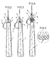
- Fig. 1
- represents a cable knife equipped with fixing jaws, the clamp being shown in the raised position for reasons of clarity,
- Fig. 2
- represents a proposed cable knife in a front view and
- Fig. 3
- represents a cable knife with a held cable with a small diameter,
- Fig. 4
- shows a cable knife with a large diameter cable and held therein
- Fig. 5
- shows an enlarged view of a section along the line 4 - 4 of FIG. 3.
Ein Kabelmesser 1 - wie es auch zur Zeit entsprechend des
Standes der Technik verwendet wird - besteht im wesentlichen
aus einem Handgriff 2, einem Messer 3, das mittels eines am
unteren Ende des Handgriffes 2 angeordneten Betätigungsrades
4 drehbar ausgestaltet ist und auch in der Höhe verstellbar
ist.A cable knife 1 - as is currently the case
State of the art is used - essentially exists
from a
Darüber hinaus ist an dem Kabelmesser 1 ein Klemmbügel 5
angeordnet, der federbeaufschlagt ist und stets in Richtung des
Messers 3 zurückgezogen wird, wie dies aus Fig. 2 ersichtlich
ist. Der Klemmbügel 5 weist eine Aufweitung 6 auf, in der der
Klemmbügel 5 vom Handgriff 2 fortgerichtet ist und sich in dem
oberen Bereich wieder der Verlängerung des Handgriffes 2 nähert.
In dem oberen Bereich des Klemmbügels 5 ragt der
Klemmbügel 5 über das Messer 3 und ist in seinem weiteren
Verlauf wieder nach unten gerichtet, so daß sich letztendlich
eine V-förmige Ausbildung des Klemmbügels 5 in seinem oberen
Bereich ergibt und in diesem Bereich wirkt der Klemmbügel
5 als Klemmfläche 7, die, wenn ein Kabel 8 entsprechend Fig. 3
zwischen die Klemmfläche 7 und den Handgriff 2 gelegt wird, mit
der Klemmfläche 7 das Kabel 8 gegen die Stirnseite des Handgriffes
2 und somit gegen das Messer 3 preßt.In addition, there is a
An dem oberen Bereich des Klemmbügels 5 kann zudem eine
Hakenklinge 8 und eine gerade Klinge 9 angeordnet sein, um
auch mit diesen Klingen ein zusätzliches Arbeiten am Kabel zu
ermöglichen.At the top of the
Die Aufweitung 6 des Klemmbügels 5 ermöglicht zum einen eine
einfache Betätigung, da beim Druck gegen die Aufweitung 6 mittels
des Daumens der Klemmbügel 5 in einfacher Weise nach
oben entgegen der Federkraft geschoben werden kann. Zudem
ermöglicht die Aufweitung 6 die Aufnahme von dicken Kabeln,
die entsprechend Fig. 4 sogar einen größeren Durchmesser
haben können als es der oberen Stärke des Handgriffes 2 entspricht.The widening 6 of the
Um eine größere Variabilität bei den mit einem Kabelmesser 1
zu verarbeitenden Kabeldurchmessern zu erreichen, wird nun
vorgeschlagen, im Klemmbereich des Klemmbügels 5 zusätzliche
Fixierbacken 10, 11 vorzusehen, durch die, wie auch aus
den Fig. 2 bis 4 ersichtlich wird, der lichte Abstand zwischen
Klemmvorrichtung und Messer 3 bzw. Oberfläche des Handgriffes
2 reduziert wird. Dies ermöglicht also auch die klemmende
Fixierung von sehr dünnen Kabeln und ermöglicht ebenfalls die
Verarbeitung von dicken Kabeln. In besonderen Fällen können
die Fixierbacken 10 und 11 in diesem Ausführungsbeispiel abgenommen
werden, um besonders dicke Kabel verarbeiten zu
können.For greater variability when using a
In diesem Ausführungsbeispiel sind die Fixierbacken 10 und 11
aus Kunststoff gefertigt, um zum einen leicht zu sein und zum
anderen eine kostengünstige Produktion zu ermöglichen. Zudem
kann ein derartiger Kunststoff gewählt werden, so daß ein
ungewolltes Rutschen des Kabels an den Fixierbacken 10 und
11 vermieden wird. Wie aus der Detailzeichnung Fig. 5 ersichtlich
wird, hintergreift die Fixierbacke 11 an seinen beiden Seiten
den Klemmbügel 5. Die hintergreifenden Rastnasen haben jeweils
eine schräge Oberfläche und ermöglichen daher, wenn die
Fixierbacken 10 und 11 auf den Klemmbügel 5 gedrückt werden,
ein leichtes Aufclipsen der Fixierbacken.In this exemplary embodiment, the
In diesem Ausführungsbeispiel sind die beiden Fixierbacken 10
und 11 miteinander gelenkig verbunden und in diesem Ausführungsbeispiel
wird ein Filmscharnier 15 verwendet. Dies hat den
Vorteil, daß die beiden Fixierbacken 10 und 11 einteilig ausgebildet
sind und daher besonders einfach montiert werden
können. Zudem verhindert das Gelenk bzw. Filmscharnier 15,
daß die Fixierbacken 10 und 11 auf dem Klemmbügel 5 verrutschen.
Das Gelenk kann den Vorteil haben, daß die Fixierbacken
10, 11 in gerader Form platzsparend transportiert
werden können und sich trotzdem bei der Montage an das
Kabelmesser der Form des Klemmbügels 5 anpassen können.
Die Fixierbacken 10, 11 können aber auch durch einen festen
Steg miteinander verbunden werden, um besonders stabil zu
sein.In this exemplary embodiment, the two
Selbstverständlich ist es auch möglich, die Fixierbacken 10 und
11 unlösbar an dem Klemmbügel 5 anzuordnen bzw. den
Klemmbügel 5 derart auszubilden, daß er durch eine entsprechende
Formgebung bereits die Funktion der beschriebenen
Fixierbacken 10 und 11 übernimmt, z. B. d. h. eine entsprechende
Profilgebung.Of course, it is also possible to fix the
Bezugnehmend auf Fig. 3 ist zusätzlich dargestellt, daß von den
vorgeschlagenen Kabelmessern auch sehr dünne Kabel 16 gehalten
werden können, ohne daß hier auf eine andere Version
des Kabelmessers zurückgegriffen werden muß, wie es zur Zeit
gemäß des Standes der Technik erforderlich ist.3, it is additionally shown that of the
proposed cable knives also kept very
Claims (8)
Applications Claiming Priority (2)
| Application Number | Priority Date | Filing Date | Title |
|---|---|---|---|
| DE10001002 | 2000-01-12 | ||
| DE2000101002 DE10001002C1 (en) | 2000-01-12 | 2000-01-12 | Cable stripping tool has handgrip provided with clamp strap with fixing plates for holding cable against stripping knife |
Publications (3)
| Publication Number | Publication Date |
|---|---|
| EP1117163A2 true EP1117163A2 (en) | 2001-07-18 |
| EP1117163A3 EP1117163A3 (en) | 2002-02-27 |
| EP1117163B1 EP1117163B1 (en) | 2006-07-05 |
Family
ID=7627292
Family Applications (1)
| Application Number | Title | Priority Date | Filing Date |
|---|---|---|---|
| EP20010100574 Expired - Lifetime EP1117163B1 (en) | 2000-01-12 | 2001-01-10 | Cable knife |
Country Status (3)
| Country | Link |
|---|---|
| EP (1) | EP1117163B1 (en) |
| DE (1) | DE10001002C1 (en) |
| ES (1) | ES2266026T3 (en) |
Cited By (1)
| Publication number | Priority date | Publication date | Assignee | Title |
|---|---|---|---|---|
| CN115241810A (en) * | 2022-09-23 | 2022-10-25 | 国网山东省电力公司高密市供电公司 | Peeling device and peeling method for distribution box cable |
Families Citing this family (3)
| Publication number | Priority date | Publication date | Assignee | Title |
|---|---|---|---|---|
| DE102015104906B3 (en) * | 2015-03-30 | 2016-08-04 | Krampe Immobilien Gmbh & Co. Kg | Cable knife with two blades |
| DE102016103972A1 (en) | 2016-03-04 | 2017-09-07 | Knipex-Werk C. Gustav Putsch Kg | cable knife |
| WO2024002876A1 (en) * | 2022-06-28 | 2024-01-04 | Weicon Gmbh & Co Kg | Cable stripping knife for ribbon cables |
Citations (2)
| Publication number | Priority date | Publication date | Assignee | Title |
|---|---|---|---|---|
| GB2133226A (en) * | 1983-01-07 | 1984-07-18 | Zdzislaw Bieganski | Cable stripper |
| US4472877A (en) * | 1980-08-29 | 1984-09-25 | C.A. Weidmuller Gmbh & Co. | Tool for removing insulation from cables |
Family Cites Families (1)
| Publication number | Priority date | Publication date | Assignee | Title |
|---|---|---|---|---|
| DE1665498B1 (en) * | 1967-11-18 | 1970-09-03 | Rittmeyer Feintechnik | Stripping tool for electrical cables |
-
2000
- 2000-01-12 DE DE2000101002 patent/DE10001002C1/en not_active Expired - Fee Related
-
2001
- 2001-01-10 ES ES01100574T patent/ES2266026T3/en not_active Expired - Lifetime
- 2001-01-10 EP EP20010100574 patent/EP1117163B1/en not_active Expired - Lifetime
Patent Citations (2)
| Publication number | Priority date | Publication date | Assignee | Title |
|---|---|---|---|---|
| US4472877A (en) * | 1980-08-29 | 1984-09-25 | C.A. Weidmuller Gmbh & Co. | Tool for removing insulation from cables |
| GB2133226A (en) * | 1983-01-07 | 1984-07-18 | Zdzislaw Bieganski | Cable stripper |
Cited By (2)
| Publication number | Priority date | Publication date | Assignee | Title |
|---|---|---|---|---|
| CN115241810A (en) * | 2022-09-23 | 2022-10-25 | 国网山东省电力公司高密市供电公司 | Peeling device and peeling method for distribution box cable |
| CN115241810B (en) * | 2022-09-23 | 2022-12-02 | 国网山东省电力公司高密市供电公司 | Peeling device and peeling method for distribution box cable |
Also Published As
| Publication number | Publication date |
|---|---|
| DE10001002C1 (en) | 2001-06-21 |
| EP1117163A3 (en) | 2002-02-27 |
| EP1117163B1 (en) | 2006-07-05 |
| ES2266026T3 (en) | 2007-03-01 |
Similar Documents
| Publication | Publication Date | Title |
|---|---|---|
| EP0314894B1 (en) | Cardboard safety cutter | |
| DE102006018129B4 (en) | Spring terminal with a leg spring arranged in a housing | |
| EP0307491A1 (en) | Surgical instrument for inserting steel rods into bones | |
| EP3263800A1 (en) | Skimming tool | |
| EP1682015B1 (en) | Tick remover | |
| CH663861A5 (en) | INSULATING PLIERS FOR LADDERS. | |
| EP1319456A1 (en) | Cable cutter | |
| EP1117163B1 (en) | Cable knife | |
| EP2929988B1 (en) | Marking device for a pipe cutter | |
| DE3813342C2 (en) | Clamping device | |
| DE102010000558A1 (en) | Pliers e.g. combination pliers, have legs supported with each other in knuckle region, and locking part actuated in closed and open positions of pliers by movement in longitudinal direction of legs of fingers | |
| DE4424493C2 (en) | Plier-like tool for the positive connection of sheet metal parts | |
| AT504125B1 (en) | Woodcracker for splitting tree trunks, for example, has C-shaped stripper for each of two arms and is detachably or adjustably connected to body of woodcracker, and end faces of strippers lie in plane normal to movement of points of arms | |
| DE2942872A1 (en) | WIPER CLAMP FOR ATTACHING A WIPER ARM TO THE BRACKET OF A WIPER BLADE | |
| DE2200516A1 (en) | Wire stripper | |
| DE2322678A1 (en) | ADJUSTABLE WRENCH | |
| EP2845693B1 (en) | Adapter connection for a tool | |
| DE3139052A1 (en) | Device for cracking nuts or the like | |
| DE102008059612B4 (en) | Hand-operated rod-shaped tool | |
| DE2238668A1 (en) | WIRE CUTTERS WITH HOLDING DEVICE FOR THE PINCHED WIRE END | |
| DE636706C (en) | Device for attaching stems to work equipment such. B. wipers, scrubbers, brooms and. Like., By means of a two-part sheet metal sleeve | |
| DE2526042A1 (en) | ONE-PIECE STRAIN RELIEF SOCKET | |
| EP0061066B1 (en) | Furrow opener | |
| EP0440856B1 (en) | Knife with sheath | |
| DE3005613A1 (en) | DEVICE FOR INTERCHANGEABLE HOLDING OF A SCRAPER OF A TOOL ON A TOOL CARRIER OF A METAL WORKING MACHINE AND TOOL FOR REPLACING THE SCRAPER |
Legal Events
| Date | Code | Title | Description |
|---|---|---|---|
| PUAI | Public reference made under article 153(3) epc to a published international application that has entered the european phase |
Free format text: ORIGINAL CODE: 0009012 |
|
| AK | Designated contracting states |
Kind code of ref document: A2 Designated state(s): AT BE CH CY DE DK ES FI FR GB GR IE IT LI LU MC NL PT SE TR Kind code of ref document: A2 Designated state(s): AT BE CH CY DE LI |
|
| AX | Request for extension of the european patent |
Free format text: AL;LT;LV;MK;RO;SI |
|
| PUAL | Search report despatched |
Free format text: ORIGINAL CODE: 0009013 |
|
| AK | Designated contracting states |
Kind code of ref document: A3 Designated state(s): AT BE CH CY DE DK ES FI FR GB GR IE IT LI LU MC NL PT SE TR |
|
| AX | Request for extension of the european patent |
Free format text: AL;LT;LV;MK;RO;SI |
|
| RAP3 | Party data changed (applicant data changed or rights of an application transferred) |
Owner name: WEICON GMBH & CO KG |
|
| 17P | Request for examination filed |
Effective date: 20020213 |
|
| AKX | Designation fees paid |
Free format text: AT BE CH CY DE LI |
|
| AXX | Extension fees paid |
Free format text: SI PAYMENT 20020213 |
|
| RBV | Designated contracting states (corrected) |
Designated state(s): ES FR IT NL SE |
|
| REG | Reference to a national code |
Ref country code: DE Ref legal event code: 8566 |
|
| 17Q | First examination report despatched |
Effective date: 20050629 |
|
| GRAP | Despatch of communication of intention to grant a patent |
Free format text: ORIGINAL CODE: EPIDOSNIGR1 |
|
| GRAS | Grant fee paid |
Free format text: ORIGINAL CODE: EPIDOSNIGR3 |
|
| GRAA | (expected) grant |
Free format text: ORIGINAL CODE: 0009210 |
|
| AK | Designated contracting states |
Kind code of ref document: B1 Designated state(s): ES FR IT NL SE |
|
| AX | Request for extension of the european patent |
Extension state: SI |
|
| PG25 | Lapsed in a contracting state [announced via postgrant information from national office to epo] |
Ref country code: IT Free format text: LAPSE BECAUSE OF FAILURE TO SUBMIT A TRANSLATION OF THE DESCRIPTION OR TO PAY THE FEE WITHIN THE PRESCRIBED TIME-LIMIT;WARNING: LAPSES OF ITALIAN PATENTS WITH EFFECTIVE DATE BEFORE 2007 MAY HAVE OCCURRED AT ANY TIME BEFORE 2007. THE CORRECT EFFECTIVE DATE MAY BE DIFFERENT FROM THE ONE RECORDED. Effective date: 20060705 |
|
| PG25 | Lapsed in a contracting state [announced via postgrant information from national office to epo] |
Ref country code: SE Free format text: LAPSE BECAUSE OF FAILURE TO SUBMIT A TRANSLATION OF THE DESCRIPTION OR TO PAY THE FEE WITHIN THE PRESCRIBED TIME-LIMIT Effective date: 20061005 |
|
| PGFP | Annual fee paid to national office [announced via postgrant information from national office to epo] |
Ref country code: NL Payment date: 20070117 Year of fee payment: 7 |
|
| PGFP | Annual fee paid to national office [announced via postgrant information from national office to epo] |
Ref country code: ES Payment date: 20070125 Year of fee payment: 7 |
|
| ET | Fr: translation filed | ||
| REG | Reference to a national code |
Ref country code: ES Ref legal event code: FG2A Ref document number: 2266026 Country of ref document: ES Kind code of ref document: T3 |
|
| PLBE | No opposition filed within time limit |
Free format text: ORIGINAL CODE: 0009261 |
|
| STAA | Information on the status of an ep patent application or granted ep patent |
Free format text: STATUS: NO OPPOSITION FILED WITHIN TIME LIMIT |
|
| 26N | No opposition filed |
Effective date: 20070410 |
|
| PGFP | Annual fee paid to national office [announced via postgrant information from national office to epo] |
Ref country code: IT Payment date: 20070531 Year of fee payment: 7 |
|
| PGFP | Annual fee paid to national office [announced via postgrant information from national office to epo] |
Ref country code: FR Payment date: 20070118 Year of fee payment: 7 |
|
| NLV4 | Nl: lapsed or anulled due to non-payment of the annual fee |
Effective date: 20080801 |
|
| PG25 | Lapsed in a contracting state [announced via postgrant information from national office to epo] |
Ref country code: NL Free format text: LAPSE BECAUSE OF NON-PAYMENT OF DUE FEES Effective date: 20080801 |
|
| REG | Reference to a national code |
Ref country code: FR Ref legal event code: ST Effective date: 20081029 |
|
| REG | Reference to a national code |
Ref country code: ES Ref legal event code: FD2A Effective date: 20080111 |
|
| PG25 | Lapsed in a contracting state [announced via postgrant information from national office to epo] |
Ref country code: FR Free format text: LAPSE BECAUSE OF NON-PAYMENT OF DUE FEES Effective date: 20080131 |
|
| PG25 | Lapsed in a contracting state [announced via postgrant information from national office to epo] |
Ref country code: ES Free format text: LAPSE BECAUSE OF NON-PAYMENT OF DUE FEES Effective date: 20080111 |
|
| PG25 | Lapsed in a contracting state [announced via postgrant information from national office to epo] |
Ref country code: IT Free format text: LAPSE BECAUSE OF NON-PAYMENT OF DUE FEES Effective date: 20080110 |