EP1117106A2 - Wire harness assembly line and wheeled worktables - Google Patents
Wire harness assembly line and wheeled worktables Download PDFInfo
- Publication number
- EP1117106A2 EP1117106A2 EP01100381A EP01100381A EP1117106A2 EP 1117106 A2 EP1117106 A2 EP 1117106A2 EP 01100381 A EP01100381 A EP 01100381A EP 01100381 A EP01100381 A EP 01100381A EP 1117106 A2 EP1117106 A2 EP 1117106A2
- Authority
- EP
- European Patent Office
- Prior art keywords
- wheeled
- worktables
- worktable
- assembly line
- sensor
- Prior art date
- Legal status (The legal status is an assumption and is not a legal conclusion. Google has not performed a legal analysis and makes no representation as to the accuracy of the status listed.)
- Withdrawn
Links
Images





Classifications
-
- H—ELECTRICITY
- H01—ELECTRIC ELEMENTS
- H01B—CABLES; CONDUCTORS; INSULATORS; SELECTION OF MATERIALS FOR THEIR CONDUCTIVE, INSULATING OR DIELECTRIC PROPERTIES
- H01B13/00—Apparatus or processes specially adapted for manufacturing conductors or cables
- H01B13/012—Apparatus or processes specially adapted for manufacturing conductors or cables for manufacturing wire harnesses
- H01B13/01218—Apparatus or processes specially adapted for manufacturing conductors or cables for manufacturing wire harnesses the wires being disposed by hand
- H01B13/01227—Apparatus or processes specially adapted for manufacturing conductors or cables for manufacturing wire harnesses the wires being disposed by hand using a layout board
Definitions
- the present invention relates to a wire harness assembly line.
- Fig. 11 shows an example of the conventional wheeled worktable conveyance line that is driven with an endless chain.
- a straight outbound passage 23 and a straight return passage 24 are installed parallel as conveyance passages of wheeled worktables 21 and both ends are connected with turning parts 25 and 26 making a closed passage, wherein an endless driving chain 22 is installed along the closed passage with the aforenamed wheeled worktables linked with the chain 22 in the order of the processes and moved in one direction with chain 22 driven by a motor Mc.
- Operators m are shown respectively behind the wheeled worktables 21 in the figure and each of the operators m assembles parts on the operation chart board on the wheeled worktable 21 on arrival of the wheeled worktable 21 at the position of the operator m.
- Both the turning parts 25 and 26 are simply places for directional changes of the wheeled worktables 21, and no work is done there.
- An entrance 27 for finished products from a previous process is built on the outbound passage side of the turning part 26 while an exit 28 for the finished product in this assembly line is built on the return passage side.
- the invention is purposed to solve the above-described problems in the conventional wire harness assembly line, making the assembly line in the form that can afford any change in the assembly line configuration on rise of any need for change in the production amount and/or in such the production form, such as the model, and that can afford the change without troublesome operations and at low costs, with successful prevention of any decrease in the assembly line conveyance efficiency, or accordingly any decrease in the production efficiency.
- the invention has a structure wherein each of the wheeled worktables travels self-dependently with drive of a motor while being isolated from the others and wherein each of the wheeled worktables is equipped with a sensor for travel along predetermined conveyance passage on a floor while objects of recognition by the sensor are installed along the predetermined route on the floor surface.
- the structure enables assembly line change only with replacement of the sensor recognition objects and rerouting of the wheeled worktable conveyance passage.
- the recognition object of the sensor is usually an optical recognition tape or a magnetic recognition tape that is attached to a floor where the wheeled worktables travel and that is easy to be attached and removed. Since the conveyance route can be modified into any desired form only by the tape replacement, an optimum rerouting that eliminate every unnecessary space between adjacent wheeled worktables with setting of a maximum conveyance efficiency (accordingly the production efficiency) is available at any increase or decrease in the wheeled worktable number. Moreover, the cost is small.
- a rectangle whose center line is parallel to a travelling direction of the wheeled worktable is defined on the bottom surface of the wheeled worktable while an isosceles triangle whose base and height are equal is defined in such manner that an symmetry axis thereof overlaps the center line of the rectangle with the base including a midpoint of the rectangle and by that a driving wheel that has a steering function is disposed at a vertex of the isosceles triangle while trailing wheels are securely disposed at both ends of the base in such manner that the revolving surfaces thereof are always in a direction parallel to the travelling direction of the wheeled worktable.
- this configuration enables reduction of the entire assembly line size since the turnabout of the wheeled worktable at the turning part of the assembly line can be carried out most efficiently with a small turn to result with reduction in the space occupation at the turning part.
- Fig. 1 shows an embodiment as a wheeled worktable 1, wherein an entire body of a wheeled base part 2 is formed with square pipes into a hexahedron, which is provided with wheels 3 at the bottom and an operation chart board 4 (an assembly chart board) on the upper surface.
- the wheels 3 consist of four auxiliary wheels 3c that are installed in the four corners of a rectangular bottom of the wheeled worktable 1 and a driving wheel 3m and two trailing wheels 3s that are installed at the center part.
- the driving wheel 3m that is driven by a motor M that is suspended from the bottom of the wheeled worktable 1 has a steering function while rotational surfaces of the trailing wheels 3s are always maintained parallel in the travelling direction (longitudinal direction) of the wheeled worktable 1.
- the auxiliary wheels 3c are designed only for stable support of the wheeled worktable 1, and each of the rotational surfaces can rotate 360 freely on a vertical axis.
- a sensor inducement system for travel of the wheeled worktable 1 along the predetermined conveyance route is installed between the above-described self-driven wheeled worktable 1 and the floor 11 where it moves.
- a sensor (an optical recognition device) 5 is mounted on the bottom of the wheeled worktable 1 while an optical recognition tape T which is a recognition object of the sensor 5 is attached to a surface of the floor 11 along the predetermined conveyance route.
- the wheeled worktable 1 whose sensor 5 recognizes the optical recognition tape T is enabled to travel without deviating from the conveyance route.
- this wheeled worktable 1 is a self-travelling wheeled conveyance worktable which travel automatically along the predetermined route by the driving wheel 3m that is driven by the motor M and the above-described sensor inducement system.
- Figs. 2 through 4 modally show a conveyance passage 12 and a wire harness assembly line along which the wheeled worktables 1 travel, wherein, as shown in the figures, in the same manner as in the case of the above-described conventional endless chain, a straight outbound passage 13 and a straight return passage 14 are provided parallel with both ends thereof connected to turning parts 15 and 16 making a closed passage, and wherein the aforenamed optical recognition tape T is attached along the closed conveyance passage 12.
- White arrows 17 and 18 over and below the turning part 16 to the right in the figures of the conveyance passage 12 indicate incoming and outgoing of the products to this assembly line, wherein the lower arrow 17 indicates incoming finished products from the previous process of the assembly line while the upper arrow 18 indicates outgoing finish products from this assembly line to the next process.
- the assembly line where the self-travelling wheeled worktable 1 moves is different from the assembly line that is formed through securing of the conventional endless chain 22 as shown in Fig. 11 and the conveyance passage 12 can be changed into any desired way only through replacement of the optical recognition tape T on the floor 11.
- the replacing operation is not troublesome and the tape T is inexpensive; therefore, in a case of increasing or decreasing the wheeled worktables to meet a change in the production mode (ratio of the production amount and the model), the action can be taken instantaneously without elaboration.
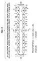
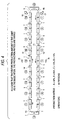
- Figs. 3 and 4 show modifications in the assembly line of the embodiment that incorporates flexibility to changes, with the production mode in Fig. 2 as a basic.
- the manufacturing models in Fig. 3 are the same A, B and C as in the basic mode in Fig. 2 above and the ratios are respectively the same 50%, 25% and 25%, the entire production amount is reduced to 80% and the number of the wheeled worktables 1 is thinned out to sixteen, which is four wheeled worktables less than in the basic mode; namely, eight wheeled worktables 1 for manufacturing of Model A, four wheeled worktables 1 for manufacturing of Model B and four wheeled worktables 1 for manufacturing of Model C. The number of operators is reduced to fourteen.
- the wheeled worktables 1 are thinned out by four wheeled worktables 1 to sixteen, since a simple operation can reduce the conveyance passage 12, the sixteen wheeled worktables 1 can be disposed without useless space between the adjacent, and thus the conveyance efficiency is maintained for 100% without fall in the production efficiency.
- the production amount and the number of the wheeled worktables 1 are the same as in the basic mode (twenty wheeled worktables 1 and 18 operators), the number of production models is increased with addition of D to the three models A, B and C and the production ratios change into 50%, 25%, 15% and 10%; namely, ten wheeled worktables 1 for manufacturing of Model A, five wheeled worktables 1 for manufacturing of Model B, three wheeled worktables 1 for manufacturing of Model C and two wheeled worktables 1 for manufacturing of Model D.
- the change in the assembly line is achieved by replacement of the wheeled worktables 1 and, since each of the wheeled worktables 1 is isolated from the others and induced to travel along the conveyance passage 12 by the above-described sensor inducement system at the time of travel, being totally free from any mechanical restraint, such as linkage with the chain in the case of endless-chain assembly line, the replacement involves no troublesome operation, such as removal and reattachment of the chain, and thus prevents the time loss for that much.
- this embodiment enables construction of the assembly line wherein the shape of conveyance passage 12 for the wheeled worktables 1 can be changed into any desired form without causing a fall in the conveyance efficiency and, in the case of replacing the wheeled worktables 1, the wheeled worktables 1 can be increased and decreased without causing a time loss for the replacement.
- the sensor inducement system in this embodiment is of the optical recognition type and the recognition object is the optical recognition tape
- the sensor of a magnetic perception type with use of a magnetic recognition tape as the recognition object is also available.
- the embodiment goes further with reduction in the occupation area of the assembly line through contrivance in the layout of the wheels 3 of the wheeled worktable 1. That is, of the three kinds of the wheels 3, which are the driving wheel 3m, the trailing wheel 3s and auxiliary wheels 3c, the layout of the driving wheel 3m and the trailing wheels 3s is specified in a certain shape to minimize the turning locus at the turning parts 15 and 16 of the conveyance passage 12. As described above, the auxiliary wheels 3c are purposed only for stable support of the wheeled worktable 1.
- Fig. 5 modally shows the layout of the wheels 3 that are provided on the bottom of the wheeled worktable 1 (wheeled base part 2) in this embodiment.
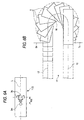
- Fig. 6A is a sketch of the driving wheel 3m and the trailing wheels 3s as an exclusive extract from Fig. 5 and Fig. 6B shows the locus of the wheeled worktable 1 with this wheel layout when turning at the right turning part 16 in the above-described conveyance passage 12. Since the assembly line is formed in a symmetrical shape, it is similar at the left turning part 15.
- Fig. 7 shows a locus of the wheeled worktable 1 with the same external shape of the bottom when turning at the turning part in the conventional assembly line that is driven with the endless chain.
- FIGs. 8 through 10 show the loci of the wheeled worktables 1 of other embodiments together with different wheel layouts (drawing A in each of the figures) when turning at the same turning part 16 (the same as at the turning part 15).
- each of the wheel layout drawings shows only the driving wheel 3m and the trailing wheels 3s. The following paragraphs describe on the differences in the turning manners of the wheeled worktables 1 of the embodiment and the variations for the comparison.
- the wheeled worktable 1 of this embodiment has a long side a of 2800 mm and a short side b of 800 mm, which is common to those of the variations for comparison in Figs. 8 through 10.
- the driving wheel 3m that has the steering wheel function is provided at the position on the center line L that is parallel to the long side a of the rectangle and at 600 mm to the left in the figure from the midpoint o of the center line.
- the two trailing wheels 3s are provided on an orthogonal line of the center line L, which crosses at the midpoint o of the center line L, at symmetrical positions 600 mm apart on both sides of the above-described center line L.
- the trailing wheels 3s are securely disposed so that the rotating sides thereof are always parallel to the longitudinal direction of the wheeled worktable 1.
- the turning locus of the wheeled worktable 1 in Fig. 5 (and Fig. 6A) at the turning part 16 is symmetric against the center line of the conveyance passage 12, with equal shapes of warps on both the outgoing passage side 13 and return passage side 14, which is the same as in the case of the conventional endless chain drive shown in Fig. 7.
- the one shown in Fig. 8 has a wheel layout as shown in Fig. 8A, wherein the driving wheel 3m is provided at the center o of the bottom of the wheeled worktable 1 while the two trailing wheels 3s are provided on a line that crosses the center line L at a position 1000 mm apart to the right in the figure from the above-described center o on the center line L, at symmetrical positions 600 mm apart on both sides of the center line L.
- the turning locus of the wheeled worktable 1 at the turning part 16 is as shown in Fig. 8B and, for a purpose of comparison with the above-described Fig. 6B, the outer locus of the wheeled worktable 1 in Fig. 6B is shown with a one-dot-one-dash line in Figs. 8B, 9B and 10B, with additional indication of a position S 6 for a shift of the wheeled worktable 1 from the straight return passage 14 to the turning part 16 and position T 6 for a shift from the turning part 16 to the straight outbound passage 13.
- the locus of the wheeled worktable 1 in Fig. 8 occupies extra space that protrudes from the circle, in comparison with the one-dot-one-dash line that shows locus of the wheeled worktable 1 in Fig. 6.
- the wheel layout of the one in Fig. 9 is as shown in Fig. 9A, wherein the two trailing wheels 3s are disposed on an orthogonal line that crosses the center line L at the center o of the bottom and 600 mm apart symmetrically on both sides of the center line L while the driving wheel 3m is disposed on the center line L and at a position 1000 mm apart from the center o to the left in the figure.
- the locus of the wheeled worktable 1 turning at the turning part 16 is as shown in Fig. 9B.
- the locus in this case is within the circle and the occupied space is reduced.
- the shift timing of the wheeled worktable 1 from the return passage 14 to the turning part 16 is early since the shift position S 9 is on the upstream side of the position S 6 in the case of Fig. 6, which is superior to the case in Fig. 6, the shift timing from the turning part 16 to the straight outbound passage 13 is late since the position T 9 is on the downstream side of the conveyance passage 12 compared with the position T 6 in Fig. 6, and this delay in the timing so great as leaving some useless part behind after canceling out the foregoing advantageous result; this concludes that the extra space is occupied in this case by comparison with the one in Fig. 6.
- the wheel layout of the one in Fig. 10 is as shown in Fig. 10A, wherein the driving wheel 3m is disposed on the center line L and at a position 600 mm apart from the center o to the left in the figure while the two trailing wheels 3s are disposed on an orthogonal line that crosses the center line L at the center o of the bottom and 600 mm apart symmetrically on both sides of the center line L.
- the locus of the wheeled worktable 1 turning at the turning part 16 is as shown in Fig. 10B.
- the locus in this case is also within the circle and the occupied space is reduced.
- the shift position S 10 of the wheeled worktable 1 from the return passage 14 to the turning part 16 is approximately the same as the position S 6 in the case of Fig. 6, the shift timing from the turning part 16 to the straight outbound passage 13 is late since the position T 10 is considerably far on the downstream side of the conveyance passage 12, compared with the position T 6 in Fig. 6, and this also concludes that the extra space is occupied in this case in the same way as the in the case in Fig. 9.
- the wheel layout in this embodiment can minimize the occupation area of the turning locus of the wheeled worktable 1 at the turning part 16 (15) and the assembly line with the best space occupation efficiency as a whole can be constructed.
- a driving wheel that has a steering function is disposed at a vertex of an isosceles triangle Tr that is defined as an isosceles triangle Tr whose base dl and height d2 are equal is defined in such manner that a symmetry axis thereof overlaps the center line L in the longitudinal direction (travelling direction of the wheeled worktable 1) and whose base dl includes a midpoint of the center line L while trailing wheels are securely disposed at both ends of the base dl in such manner that the revolving surfaces thereof are always in a direction parallel to the travelling direction of the wheeled worktable 1.
- each of the wheeled worktables moving in the assembly line travels self-dependently with drive of the motor while being isolated from the others and wherein each of the wheeled worktables is equipped with the sensor and inducted by the sensor recognition objects that are installed along the predetermined route on the floor surface enables modification of the conveyance passage for any increase or decrease in the wheeled worktables only with replacement of the sensor recognition objects and thus the conveyance route can be modified into any desired form by the simple operation without causing any degradation in the conveyance efficiency at the increase or decrease in the wheeled worktable number.
- each of the wheeled worktables are isolated from the others and induced along the conveyance passage only with the sensor inducement system, being free from any mechanical restraint, there is no need for such labor and time for dismounting from and remounting on the chain as in the case of the assembly line driven with the endless chain.
- the wheeled worktable that has the configuration wherein the rectangle whose center line is parallel to the travelling direction of the wheeled worktable is defined on the bottom surface of the wheeled worktable while the isosceles triangle whose base and height are equal is defined in such manner that the symmetry axis thereof overlaps the center line of the rectangle with the base including the midpoint of the rectangle and wherein the driving wheel that has the steering function is disposed at the vertex of the isosceles triangle while the trailing wheels are securely disposed at both ends of the base in such manner that the revolving surfaces thereof are always in the direction parallel to the travelling direction of the wheeled worktable, the turning loci at the turning parts can be minimized and thus the assembly-line occupation area may be reduced.
Landscapes
- Engineering & Computer Science (AREA)
- Manufacturing & Machinery (AREA)
- Automatic Assembly (AREA)
- Specific Conveyance Elements (AREA)
- Supply And Installment Of Electrical Components (AREA)
Abstract
Description
(1) In a case of change in production mode (production amount or production model) as the object of line manufacturing, the aforenamed
Claims (2)
- A wire harness assembly line where wire harnesses are assembled while wheeled worktables are moved in sequence of processes; comprising:each of said wheeled worktables which travels self-dependently with drive of a motor while being isolated from the others, andeach of said wheeled worktables which includes a sensor for travel along predetermined conveyance passage on a floor while objects of recognition by said sensor are installed along said predetermined route on said floor surface.
- The wheeled worktable for use in the assembly line according to Claim 1, whereinon a bottom surface of said wheeled worktable, a rectangle whose center line is parallel to a travelling direction of the wheeled worktable is defined while an isosceles triangle whose base and height are equal is defined in such manner that an symmetry axis thereof overlaps the center line of said rectangle with the base including a midpoint of said rectangle,said wheeled worktable comprising:a driving wheel that has a steering function disposed at a vertex of said isosceles triangle, andtrailing wheels that are securely disposed at both ends of the base in such manner that the revolving surfaces thereof are always in a direction parallel to the travelling direction of the wheeled worktable.
Applications Claiming Priority (2)
| Application Number | Priority Date | Filing Date | Title |
|---|---|---|---|
| JP2000002447A JP2001195930A (en) | 2000-01-11 | 2000-01-11 | Wire harness assembly line and work cart |
| JP2000002447 | 2000-01-11 |
Publications (2)
| Publication Number | Publication Date |
|---|---|
| EP1117106A2 true EP1117106A2 (en) | 2001-07-18 |
| EP1117106A3 EP1117106A3 (en) | 2002-01-30 |
Family
ID=18531553
Family Applications (1)
| Application Number | Title | Priority Date | Filing Date |
|---|---|---|---|
| EP01100381A Withdrawn EP1117106A3 (en) | 2000-01-11 | 2001-01-05 | Wire harness assembly line and wheeled worktables |
Country Status (4)
| Country | Link |
|---|---|
| US (1) | US6446743B2 (en) |
| EP (1) | EP1117106A3 (en) |
| JP (1) | JP2001195930A (en) |
| CN (1) | CN1303810A (en) |
Cited By (4)
| Publication number | Priority date | Publication date | Assignee | Title |
|---|---|---|---|---|
| RU2399107C1 (en) * | 2009-03-30 | 2010-09-10 | Николай Павлович Игнатьев | Conveyor for assembly of items, preferably wire strands |
| ES2407954R1 (en) * | 2011-09-12 | 2013-09-17 | Matis Hispania S A | STEAM ACCUMULATOR TRANSPORTATION SYSTEM |
| CN107030640A (en) * | 2017-06-13 | 2017-08-11 | 芜湖侨云友星电气工业有限公司 | A kind of automotive wire bundle assembly or fitting table |
| CN108827359A (en) * | 2018-04-27 | 2018-11-16 | 佛山市甄睿智能科技有限公司 | A kind of mounting device of landing sensor |
Families Citing this family (11)
| Publication number | Priority date | Publication date | Assignee | Title |
|---|---|---|---|---|
| US6857493B2 (en) * | 2002-02-13 | 2005-02-22 | Paragon Technologies, Inc. | Automatic load positioning for a conveyor cart |
| US7350613B2 (en) * | 2004-03-31 | 2008-04-01 | Jervis B. Webb Company | Transport with rotatable load and safety bumper |
| JP5169418B2 (en) * | 2008-04-14 | 2013-03-27 | 住友電装株式会社 | Assembly drawing board apparatus for wire harness and wire harness assembly method |
| US7793774B2 (en) * | 2008-07-29 | 2010-09-14 | Hubbell Incorporated | Lockout and monitoring system with SIL3 safety rating and method for lockout and monitoring |
| JP5655728B2 (en) * | 2011-07-13 | 2015-01-21 | 住友電装株式会社 | Conveyor device for assembly work |
| JP5741380B2 (en) * | 2011-10-31 | 2015-07-01 | 住友電装株式会社 | Conveyor device for assembly work |
| JP6240540B2 (en) * | 2014-03-26 | 2017-11-29 | 矢崎総業株式会社 | Wiring work equipment |
| JP6588274B2 (en) * | 2015-08-27 | 2019-10-09 | 古河電気工業株式会社 | Transport system |
| CN110103021A (en) * | 2019-05-14 | 2019-08-09 | 东莞优先家居有限公司 | Semi-automatic flow process line of sofa |
| CN114772198B (en) * | 2022-04-27 | 2024-07-09 | 中国电子科技集团公司第二十八研究所 | Novel multi-mode flexible assembly line and control method thereof |
| DE102023000977B3 (en) * | 2023-03-13 | 2024-03-28 | Mercedes-Benz Group AG | Device for transporting electrical cables |
Family Cites Families (15)
| Publication number | Priority date | Publication date | Assignee | Title |
|---|---|---|---|---|
| US4042058A (en) * | 1975-12-18 | 1977-08-16 | Lear Siegler, Inc. | Easily accessible switches for manual control of an automatically controlled vehicle |
| US5377106A (en) * | 1987-03-24 | 1994-12-27 | Fraunhofer Gesellschaft Zur Foerderung Der Angewandten Forschung E.V. | Process for navigating an unmanned vehicle and a vehicle for the same |
| US4968878A (en) * | 1989-02-07 | 1990-11-06 | Transitions Research Corporation | Dual bumper-light curtain obstacle detection sensor |
| JP2636403B2 (en) * | 1989-03-08 | 1997-07-30 | 株式会社豊田自動織機製作所 | Operation control device for unmanned vehicles |
| FR2648071B1 (en) * | 1989-06-07 | 1995-05-19 | Onet | SELF-CONTAINED METHOD AND APPARATUS FOR AUTOMATIC FLOOR CLEANING BY EXECUTING PROGRAMMED MISSIONS |
| US5109597A (en) | 1991-03-12 | 1992-05-05 | Northrop Corporation | Backwired 3-D harness tool assembly |
| KR940006561B1 (en) * | 1991-12-30 | 1994-07-22 | 주식회사 금성사 | Auto-drive sensor for vacuum cleaner |
| JP3123297B2 (en) | 1993-03-29 | 2001-01-09 | 住友電装株式会社 | Wire harness assembly line |
| JP3293314B2 (en) * | 1994-04-14 | 2002-06-17 | ミノルタ株式会社 | Cleaning robot |
| JPH09263140A (en) * | 1996-03-27 | 1997-10-07 | Minolta Co Ltd | Unmanned service car |
| US5935179A (en) * | 1996-04-30 | 1999-08-10 | Aktiebolaget Electrolux | System and device for a self orienting device |
| EP0837310A3 (en) * | 1996-10-18 | 1999-03-10 | SANYO ELECTRIC Co., Ltd. | Quality test system for electric appliances |
| JPH10260727A (en) * | 1997-03-21 | 1998-09-29 | Minolta Co Ltd | Self-driving work vehicle |
| FR2765152B1 (en) * | 1997-06-25 | 1999-07-30 | Michelin & Cie | METHOD FOR ASSEMBLING MOUNTED ASSEMBLIES |
| US6226830B1 (en) * | 1997-08-20 | 2001-05-08 | Philips Electronics North America Corp. | Vacuum cleaner with obstacle avoidance |
-
2000
- 2000-01-11 JP JP2000002447A patent/JP2001195930A/en active Pending
- 2000-12-29 US US09/750,053 patent/US6446743B2/en not_active Expired - Fee Related
-
2001
- 2001-01-05 EP EP01100381A patent/EP1117106A3/en not_active Withdrawn
- 2001-01-11 CN CN01103353A patent/CN1303810A/en active Pending
Cited By (5)
| Publication number | Priority date | Publication date | Assignee | Title |
|---|---|---|---|---|
| RU2399107C1 (en) * | 2009-03-30 | 2010-09-10 | Николай Павлович Игнатьев | Conveyor for assembly of items, preferably wire strands |
| ES2407954R1 (en) * | 2011-09-12 | 2013-09-17 | Matis Hispania S A | STEAM ACCUMULATOR TRANSPORTATION SYSTEM |
| CN107030640A (en) * | 2017-06-13 | 2017-08-11 | 芜湖侨云友星电气工业有限公司 | A kind of automotive wire bundle assembly or fitting table |
| CN108827359A (en) * | 2018-04-27 | 2018-11-16 | 佛山市甄睿智能科技有限公司 | A kind of mounting device of landing sensor |
| CN108827359B (en) * | 2018-04-27 | 2020-12-22 | 浙江黎盛新材料科技有限公司 | Installation device for parking platform sensor |
Also Published As
| Publication number | Publication date |
|---|---|
| US6446743B2 (en) | 2002-09-10 |
| EP1117106A3 (en) | 2002-01-30 |
| US20010026750A1 (en) | 2001-10-04 |
| JP2001195930A (en) | 2001-07-19 |
| CN1303810A (en) | 2001-07-18 |
Similar Documents
| Publication | Publication Date | Title |
|---|---|---|
| US20010026750A1 (en) | Wire harness assembly line and wheeled worktables | |
| JP3123297B2 (en) | Wire harness assembly line | |
| IT9004811A0 (en) | AIR CONVEYOR FOR A MOTOR VEHICLE ROOF | |
| DE69618134D1 (en) | Grille for air intake | |
| IT1298459B1 (en) | COMPRESSOR, IN PARTICULAR FOR THE AIR CONDITIONING SYSTEM OF A MOTOR VEHICLE | |
| EP0824179A3 (en) | Vertical blind | |
| ITVE950016A0 (en) | PANTOGRAPH LIFT FOR MOTOR VEHICLES | |
| DE69407547D1 (en) | GROUND CONNECTION FOR A WINDOW AIR CONDITIONER | |
| JPH0437174Y2 (en) | ||
| JP3447573B2 (en) | Conveyor device for vehicle assembly | |
| ITMI920280A0 (en) | SELF-ASSEMBLING SHELTER STRUCTURE FOR MOTOR VEHICLES IN GENERAL | |
| KR970015982A (en) | Ordinary self-contained three-dimensional parking lot | |
| FR2725178B1 (en) | AIRCRAFT LANDING TRAIN, SIDE LIFT TYPE | |
| CN2275414Y (en) | Multi-layer curtain rod | |
| JPS5914144Y2 (en) | split workbench | |
| JPH0413127Y2 (en) | ||
| JP2750629B2 (en) | Large building with openable roof | |
| JPH04201078A (en) | Work bench | |
| ITTO941071A0 (en) | STACKED DECK VEHICLE FOR THE TRANSPORT OF MOTOR VEHICLES. | |
| KR0126795Y1 (en) | Support structure of floor for a bus | |
| JPS6411553B2 (en) | ||
| JPS62173905A (en) | Transporting facilities by use of linear motor | |
| JPH03205290A (en) | Curved line conveyor device | |
| JP2518193B2 (en) | Transport equipment using linear motors | |
| ITMI913368A1 (en) | HEADREST FOR VEHICLES WITH REDUCED ASSEMBLY COSTS |
Legal Events
| Date | Code | Title | Description |
|---|---|---|---|
| PUAI | Public reference made under article 153(3) epc to a published international application that has entered the european phase |
Free format text: ORIGINAL CODE: 0009012 |
|
| AK | Designated contracting states |
Kind code of ref document: A2 Designated state(s): AT BE CH CY DE DK ES FI FR GB GR IE IT LI LU MC NL PT SE TR Kind code of ref document: A2 Designated state(s): DE FR GB |
|
| AX | Request for extension of the european patent |
Free format text: AL;LT;LV;MK;RO;SI |
|
| PUAL | Search report despatched |
Free format text: ORIGINAL CODE: 0009013 |
|
| AK | Designated contracting states |
Kind code of ref document: A3 Designated state(s): AT BE CH CY DE DK ES FI FR GB GR IE IT LI LU MC NL PT SE TR |
|
| AX | Request for extension of the european patent |
Free format text: AL;LT;LV;MK;RO;SI |
|
| 17P | Request for examination filed |
Effective date: 20020322 |
|
| AKX | Designation fees paid |
Free format text: DE FR GB |
|
| 17Q | First examination report despatched |
Effective date: 20030407 |
|
| STAA | Information on the status of an ep patent application or granted ep patent |
Free format text: STATUS: THE APPLICATION IS DEEMED TO BE WITHDRAWN |
|
| 18D | Application deemed to be withdrawn |
Effective date: 20030819 |