EP1116931B1 - Vorrichtung zum Positionieren von Messgeräten - Google Patents
Vorrichtung zum Positionieren von Messgeräten Download PDFInfo
- Publication number
- EP1116931B1 EP1116931B1 EP00810022A EP00810022A EP1116931B1 EP 1116931 B1 EP1116931 B1 EP 1116931B1 EP 00810022 A EP00810022 A EP 00810022A EP 00810022 A EP00810022 A EP 00810022A EP 1116931 B1 EP1116931 B1 EP 1116931B1
- Authority
- EP
- European Patent Office
- Prior art keywords
- track
- crossbeam
- measuring device
- measuring
- bolsters
- Prior art date
- Legal status (The legal status is an assumption and is not a legal conclusion. Google has not performed a legal analysis and makes no representation as to the accuracy of the status listed.)
- Expired - Lifetime
Links
- 229920006255 plastic film Polymers 0.000 claims description 10
- 239000002985 plastic film Substances 0.000 claims description 9
- 230000005855 radiation Effects 0.000 claims description 5
- 230000001360 synchronised effect Effects 0.000 claims description 5
- 230000005540 biological transmission Effects 0.000 claims description 4
- 230000002285 radioactive effect Effects 0.000 claims description 2
- 239000000523 sample Substances 0.000 claims 1
- 239000000463 material Substances 0.000 abstract description 15
- 238000005259 measurement Methods 0.000 description 7
- 239000011888 foil Substances 0.000 description 3
- 230000033001 locomotion Effects 0.000 description 3
- 239000004698 Polyethylene Substances 0.000 description 2
- 238000007664 blowing Methods 0.000 description 2
- 238000010276 construction Methods 0.000 description 2
- 238000001125 extrusion Methods 0.000 description 2
- -1 polyethylene Polymers 0.000 description 2
- 229920000573 polyethylene Polymers 0.000 description 2
- 238000001816 cooling Methods 0.000 description 1
- 230000007547 defect Effects 0.000 description 1
- 230000001419 dependent effect Effects 0.000 description 1
- 238000011161 development Methods 0.000 description 1
- 230000018109 developmental process Effects 0.000 description 1
- 239000003000 extruded plastic Substances 0.000 description 1
- 238000010438 heat treatment Methods 0.000 description 1
- 238000004519 manufacturing process Methods 0.000 description 1
- 238000000034 method Methods 0.000 description 1
- 238000012544 monitoring process Methods 0.000 description 1
- 238000012545 processing Methods 0.000 description 1
- 239000010453 quartz Substances 0.000 description 1
- VYPSYNLAJGMNEJ-UHFFFAOYSA-N silicon dioxide Inorganic materials O=[Si]=O VYPSYNLAJGMNEJ-UHFFFAOYSA-N 0.000 description 1
- 210000002435 tendon Anatomy 0.000 description 1
- 238000004804 winding Methods 0.000 description 1
Images


Classifications
-
- G—PHYSICS
- G01—MEASURING; TESTING
- G01B—MEASURING LENGTH, THICKNESS OR SIMILAR LINEAR DIMENSIONS; MEASURING ANGLES; MEASURING AREAS; MEASURING IRREGULARITIES OF SURFACES OR CONTOURS
- G01B5/00—Measuring arrangements characterised by the use of mechanical techniques
- G01B5/0002—Arrangements for supporting, fixing or guiding the measuring instrument or the object to be measured
- G01B5/0004—Supports
-
- B—PERFORMING OPERATIONS; TRANSPORTING
- B29—WORKING OF PLASTICS; WORKING OF SUBSTANCES IN A PLASTIC STATE IN GENERAL
- B29C—SHAPING OR JOINING OF PLASTICS; SHAPING OF MATERIAL IN A PLASTIC STATE, NOT OTHERWISE PROVIDED FOR; AFTER-TREATMENT OF THE SHAPED PRODUCTS, e.g. REPAIRING
- B29C48/00—Extrusion moulding, i.e. expressing the moulding material through a die or nozzle which imparts the desired form; Apparatus therefor
- B29C48/25—Component parts, details or accessories; Auxiliary operations
- B29C48/92—Measuring, controlling or regulating
-
- B—PERFORMING OPERATIONS; TRANSPORTING
- B29—WORKING OF PLASTICS; WORKING OF SUBSTANCES IN A PLASTIC STATE IN GENERAL
- B29C—SHAPING OR JOINING OF PLASTICS; SHAPING OF MATERIAL IN A PLASTIC STATE, NOT OTHERWISE PROVIDED FOR; AFTER-TREATMENT OF THE SHAPED PRODUCTS, e.g. REPAIRING
- B29C2948/00—Indexing scheme relating to extrusion moulding
- B29C2948/92—Measuring, controlling or regulating
- B29C2948/92009—Measured parameter
- B29C2948/92076—Position, e.g. linear or angular
-
- B—PERFORMING OPERATIONS; TRANSPORTING
- B29—WORKING OF PLASTICS; WORKING OF SUBSTANCES IN A PLASTIC STATE IN GENERAL
- B29C—SHAPING OR JOINING OF PLASTICS; SHAPING OF MATERIAL IN A PLASTIC STATE, NOT OTHERWISE PROVIDED FOR; AFTER-TREATMENT OF THE SHAPED PRODUCTS, e.g. REPAIRING
- B29C2948/00—Indexing scheme relating to extrusion moulding
- B29C2948/92—Measuring, controlling or regulating
- B29C2948/92009—Measured parameter
- B29C2948/92114—Dimensions
- B29C2948/92152—Thickness
-
- B—PERFORMING OPERATIONS; TRANSPORTING
- B29—WORKING OF PLASTICS; WORKING OF SUBSTANCES IN A PLASTIC STATE IN GENERAL
- B29C—SHAPING OR JOINING OF PLASTICS; SHAPING OF MATERIAL IN A PLASTIC STATE, NOT OTHERWISE PROVIDED FOR; AFTER-TREATMENT OF THE SHAPED PRODUCTS, e.g. REPAIRING
- B29C2948/00—Indexing scheme relating to extrusion moulding
- B29C2948/92—Measuring, controlling or regulating
- B29C2948/92323—Location or phase of measurement
- B29C2948/92428—Calibration, after-treatment, or cooling zone
-
- B—PERFORMING OPERATIONS; TRANSPORTING
- B29—WORKING OF PLASTICS; WORKING OF SUBSTANCES IN A PLASTIC STATE IN GENERAL
- B29C—SHAPING OR JOINING OF PLASTICS; SHAPING OF MATERIAL IN A PLASTIC STATE, NOT OTHERWISE PROVIDED FOR; AFTER-TREATMENT OF THE SHAPED PRODUCTS, e.g. REPAIRING
- B29C2948/00—Indexing scheme relating to extrusion moulding
- B29C2948/92—Measuring, controlling or regulating
- B29C2948/92504—Controlled parameter
- B29C2948/92571—Position, e.g. linear or angular
-
- B—PERFORMING OPERATIONS; TRANSPORTING
- B29—WORKING OF PLASTICS; WORKING OF SUBSTANCES IN A PLASTIC STATE IN GENERAL
- B29C—SHAPING OR JOINING OF PLASTICS; SHAPING OF MATERIAL IN A PLASTIC STATE, NOT OTHERWISE PROVIDED FOR; AFTER-TREATMENT OF THE SHAPED PRODUCTS, e.g. REPAIRING
- B29C2948/00—Indexing scheme relating to extrusion moulding
- B29C2948/92—Measuring, controlling or regulating
- B29C2948/92504—Controlled parameter
- B29C2948/92609—Dimensions
- B29C2948/92647—Thickness
-
- B—PERFORMING OPERATIONS; TRANSPORTING
- B29—WORKING OF PLASTICS; WORKING OF SUBSTANCES IN A PLASTIC STATE IN GENERAL
- B29C—SHAPING OR JOINING OF PLASTICS; SHAPING OF MATERIAL IN A PLASTIC STATE, NOT OTHERWISE PROVIDED FOR; AFTER-TREATMENT OF THE SHAPED PRODUCTS, e.g. REPAIRING
- B29C2948/00—Indexing scheme relating to extrusion moulding
- B29C2948/92—Measuring, controlling or regulating
- B29C2948/92819—Location or phase of control
- B29C2948/92923—Calibration, after-treatment or cooling zone
-
- B—PERFORMING OPERATIONS; TRANSPORTING
- B29—WORKING OF PLASTICS; WORKING OF SUBSTANCES IN A PLASTIC STATE IN GENERAL
- B29C—SHAPING OR JOINING OF PLASTICS; SHAPING OF MATERIAL IN A PLASTIC STATE, NOT OTHERWISE PROVIDED FOR; AFTER-TREATMENT OF THE SHAPED PRODUCTS, e.g. REPAIRING
- B29C48/00—Extrusion moulding, i.e. expressing the moulding material through a die or nozzle which imparts the desired form; Apparatus therefor
- B29C48/03—Extrusion moulding, i.e. expressing the moulding material through a die or nozzle which imparts the desired form; Apparatus therefor characterised by the shape of the extruded material at extrusion
- B29C48/09—Articles with cross-sections having partially or fully enclosed cavities, e.g. pipes or channels
- B29C48/10—Articles with cross-sections having partially or fully enclosed cavities, e.g. pipes or channels flexible, e.g. blown foils
Definitions
- the invention relates to a device for positioning measuring instruments according to the preamble of independent claim 1.
- Such devices are used, for example, to position measuring devices for determining and monitoring the thickness of plastic films in the production of these films relative to the material to be measured.
- Plastic films are extruded eg as a tube.
- an arcuate or annular track as concentric with the hose made of plastic film.
- the Einstallarm with the measuring unit and the measuring head is, for example, radially movable in a circular, ring-like path. This makes it possible to position the measuring head radially correctly with respect to the tubular material to be measured, for example.
- the measuring element of the measuring head monitors the thickness of a plastic film only at a width of a few millimeters or centimeters.
- the thickness of plastic films usually does not change suddenly and for a short time very strongly. Differences in the thickness of films are much more common over the circumference of a film extruded as a tube. Thus, differences in the thickness transversely to the running direction of the extruded film, in the so-called transverse profile, are above all recognizable. So it is sufficient in most cases, the measuring head, for. periodically over the circumference of the hose to detect defects in the thickness of the film tube. When the measuring head is moved back and forth on the annular path, one speaks for example. reverse.
- This reciprocation of the measuring device over the circumference of the tube or the orbital movement around it can be generated in various ways.
- a carriage On the rail-like path, for example, a carriage may be arranged, on which the measuring unit is mounted.
- the carriage may be self-propelled or otherwise powered, e.g. with a revolving rope or belt.
- sliding contacts can be provided as slip rings. Measurement signals and control signals can also be transmitted wirelessly.
- Previous devices for measuring the thickness of plastic films for example of extruded polyethylene films are constructed so that the web is arranged concentrically around the emerging from a blown film tube, between the blowing head and winding device.
- the measuring unit moves on the web around the moving film bubble.
- the measuring unit of the measuring unit is mounted on a radially movable arm and is therefore positioned precisely opposite the foil. The positioning may be necessary with an accuracy in the range of millimeters or fractions of a millimeter. This in particular, but not only when no part of the measuring element to touch the material to be measured, that is, when the measurement is non-contact.
- the arm can be effectively moved as a whole, but it can also be a telescopically extendable and shortenable, ie forward and retractable arm in the radial direction, on which the measuring device to be positioned of the measuring unit is attached.
- a linear motor or a pneumatic linear adjustment device may also be suitable. With a linear motor can be very fast and very finely positioned in the range of a few, for example, about 4 cm centimeters.
- the arm In a system with which, for example, tubular films with different diameters to be monitored, the arm is mounted on which the measuring element is different degrees far.
- the extension range of a built with reasonable effort arm is limited to about 50 cm to 85 cm.
- the plant is limited to use for foil tubes with differences in diameter in the range of about one to two meters.
- US 3,762,053 and DE 32 09 022 disclose processing devices having trusses that pass through the center of a web and are angularly rotatable on a path about the center.
- the present invention brings substantial improvement in this regard.
- the device has the features of the characterizing part of independent claim 1.
- the dependent claims relate to advantageous developments of the invention.
- the device for positioning a measuring device has an annular or arcuate path on which a measuring device is mounted.
- a traverse is provided, which carries the measuring device. Between rail and Traverse bearings are arranged. In the device for positioning, the position of the traverse can be changed with the measuring device relative to the web in the radial direction to the web.
- a device With a device according to the invention, it is readily possible to significantly expand the working range of the system and to ensure the mechanical stability. If a circular path has a diameter of the order of about six to seven meters, the working range of the measuring unit can easily be in the range of several meters. That is, for example, film hoses with a diameter of about one meter to eight meters can be monitored without the accuracy of the positioning would be worse. It is therefore possible with the new device according to the invention, a measuring unit, and in particular the measuring element of this measuring unit to position mechanically stable over a large area.
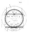
- Fig. 1 shows a device for positioning 1 of a measuring unit 10 according to the invention.
- a circular path 11 which is formed ring-segment-shaped, two carriages are arranged, which are designed as a turntable 12, 13.
- the track 11 is mounted on the rail supports 111.
- a traverse 14, with the measuring unit 10, is supported and supported on the two turntables 12, 13.
- On the turntables 12, 13 are each a pivot bearing 121, 131 and a longitudinal bearing 122, 132, so-called. Trolleys available.
- the location of the Traverse 14 opposite the bogies 12, 13 are changed both longitudinally and angularly, which is required, and it makes it possible to move the bogies 12, 13 on the web 11 toward or away from each other.
- the measuring element 100 is mounted on a telescopic arm 101 that can be pulled forward and retracted, with which the fine positioning of the measuring element 100 to the measured material takes place.
- the material to be measured may be a tube of extruded plastic film (not shown), e.g. made of polyethylene whose wall thickness is monitored by a capacitive measuring element 100.
- a tube of extruded plastic film not shown
- e.g. made of polyethylene whose wall thickness is monitored by a capacitive measuring element 100.
- radioactive radiation gamma or beta radiation.
- adjusting the position of the cross member 14 on the turntables 12, 13 mechanically with a so-called .Synchronriemen 1213 With this construction, the two turntable 12, 13 are synchronized, ie they can in the same way towards each other or away from each other be moved, so that the position of the measuring unit 10 on the respective tendon considered, for example, always remains on the center. If the traverse 14 is moved radially outwards or inwards with respect to the web 11 and if the measuring unit 10 is positioned in the middle of the string formed by the traverse 14 with the web 11, the measuring unit 10 moves radially outwards or towards Inside. For the in Fig. 1 The device shown, the maximum inner and outer position of the measuring member 100 of the measuring unit 10 with the two dash-dotted lines 15 (inside) and 16 (outside) is illustrated.
- the blow head of the extrusion system is arranged, for example, in the region of the bottom on which the device for positioning 1 stands, or one to two floors lower, concentric with the web.
- the film runs from the blowhead, from bottom to top, and is filled with air that enters the hose is blown, inflated and cooled.
- different blow heads are used. Blown film machines are generally several stories high.
- the thickness measuring device with the device for positioning is usually one to two stories higher than the extruder and the die.
- multi-layer systems in which different materials are pressed from different extruders to different locations of the blow head. These systems produce multi-layer films made of different materials.
- the traverse 14 with the measuring unit 10 of the device for positioning in the radial direction is set to the respective diameter of the bladder (not shown) by moving the two turntable 12 and 13 towards each other or away from each other (tangential arrows).
- the fine adjustment of the position of the measuring element 100 relative to the material to be measured takes place, for example. with the arm 101. But it is also possible to carry out the positioning alone with the traverse.
- the turntable 12, 13 run with the crossbar 14 on the track 11 of the device for positioning 1 forward and backward or continuously circulating around the material to be measured.
- the two turntables can use a common toothed belt for locomotion.
- the synchronization of the two turntable is e.g. The fact that both turntables are each driven with a stepper motor, which are controlled by a control quartz accurate, but otherwise independent of each other. If the stepper motors of the two turntables are driven at exactly the same frequency and in the same direction, the turntables and thus the crosshead mounted on them move around the film bubble without changing their radial distance (to the center of the circular path).
- the supply of electrical energy can be done via slip rings, over current-carrying rails of the web 11, but also via movable cables.
- the measuring and control signals can, as already described, transmitted wirelessly and / or on the power lines on which power is modulated.
- the extrusion equipment can be influenced and thus the thickness of the film can be corrected. This happens, for example, by influencing blowing air cooling elements or heating elements arranged over the circumference of the blow head. It can also be provided to move elements of the blow head mechanically, for example, to better center or position differently, such that the thickness profile of the film again as flat as possible, ie evenly.
- the average thickness of the film can also be influenced, for example, by changing the speed at which the film is pulled off.
- the drive of one or both bogies 12, 13 on the track 11 may e.g. with one or more electric motors in one or both bogies, with belts, rope, with liner drive or somehow done.
- the two extreme positions A and B of the traverse 14 are shown schematically on the turntables 12, 13 and the track 11 of a device 1 for positioning.
- the fine positioning of the measuring member 100 takes place radially with the arm 101.
- the measuring unit 10 moves practically above the track 11 and the cross member 14 approximately forms a tangent to the web 11.
- the traverse 14 forms a chord to the web 11.
- the traverse 14 can take any intermediate position between the extreme positions A and B.
- FIG. 3 schematically another embodiment of a device for positioning 3 in a plan view.
- the web 31 is here formed by two mutually rotatable and mutually rotatable (tangential arrows) rings 311 and 312.
- the cross member 34 is connected to the ring 311 with the pivot bearing 32 and connected to the ring 312 with the rotary and sliding bearings 33.
- the rotary and sliding bearing 33 is here by a Longitudinal grooves 340 formed in which a cam 330 in the direction of the longitudinal axis of the cross member 34 is displaceable.
- the traverse 34 and thus also the measuring unit 30 are positioned radially opposite the material to be measured.
- the measuring unit 30 can be displaceable in the longitudinal direction of the traverse 34 in order to be positioned in the middle of the chord formed by the traverse 34 with the track 31.
- the fine positioning of the measuring device 300 may be e.g. also done here with an arm not shown in detail.
- the two rings 311 and 312 move synchronously. This device for positioning 3 can rotate in the same direction during operation or rotate back and forth around the material to be measured.
- each store the traverse with a rotary and sliding bearings on each ring 311, 312 and thus, for example, to achieve a symmetrical arrangement of the traverse to the track 31.
- the drive of the web 31 and the rings 311 and 312 can be done with facilities as they are described for the other examples, so with electric motors u. s. w.
- the transmission of the measurement and control signals can be carried out in the same way as described in connection with the other examples.
- means for fixing the set traverse on the turntables may be provided in order to achieve the required accuracy of measurement.
- only one of the two turntables for the rotational speed can be driving determined.
- the second turntable may in this case have an asynchronous auxiliary drive.
- the synchronous drive e.g. the drive with stepper motor is required in order to achieve a uniform rotational speed and to be able to assign the thickness measurements exactly to a specific position or angular position of the measuring element. This allows the measurement results to be assigned to the angular position of the material to be measured, ie to the film tube.
- the term is to be understood radially so that an exactly radial direction is described.
- the term radial can also be understood to mean a direction which extends inwardly or outwardly parallel to a radius over all considered.
- the bogies run on the track and the trusses are mounted on the turntables or on the rings. And the measuring unit is also on the traverse. This need not necessarily be so, although these embodiments bring certain benefits.
- the turntable could be just as well hanging on the train and also the crossbar could be suspended from the hanging on these constructions. In this case, it could be advantageous if the train and thus practically the whole device would be suspended for positioning, for example, on the ceiling space to avoid relatively expensive stand structures for the web.
Landscapes
- Physics & Mathematics (AREA)
- General Physics & Mathematics (AREA)
- Engineering & Computer Science (AREA)
- Mechanical Engineering (AREA)
- Length Measuring Devices With Unspecified Measuring Means (AREA)
Description
- Die Erfindung bezieht sich auf eine Vorrichtung zum Positionieren von Messgeräten nach dem Oberbegriff des unabhängigen Anspruchs 1.
- Derartige Vorrichtungen werden beispielsweise verwendet, Messgeräte zum Bestimmen und Überwachen der Dicke von Kunststofffolien bei der Herstellung dieser Folien gegenüber dem Messgut zu positionieren. Kunststofffolien werden z.B. als Schlauch extrudiert. Um den Schlauch aus Kunststofffolie ist, in Bewegungsrichtung des Schlauchs betrachtet, kurz nach dem Extruder eine bogenförmige oder ringartige Bahn, möglichst konzentrisch zum Schlauch aus Kunststofffolie angeordnet. Auf dieser Bahn ist die eigentliche Messeinheit mit Messkopf und Einstellarm angeordnet. Der Einstallarm mit der Messeinheit und dem Messkopf ist bei einer kreisförmigen, ringartigen Bahn beispielsweise radial beweglich. Damit ist es möglich, den Messkopf radial korrekt gegenüber dem beispielsweise schlauchförmigen Messgut zu positionieren.
- Das Messorgan des Messkopfs überwacht die Dicke einer Kunststofffolie nur auf einer Breite von wenigen Millimetern oder Zentimetern. Die Dicke von Kunststofffolien ändert in der Regel nicht plötzlich und kurzzeitig sehr stark. Unterschiede in der Dicke von Folien sind wesentlich häufiger über den Umfang einer als Schlauch extrudierten Folie. Es sind also vor allem Unterschiede in der Dicke quer zur Laufrichtung der extrudierten Folie, im sog. Querprofil zu erkennen. So genügt es in den meisten Fällen, den Messkopf z.B. periodisch über den Umfang des Schlauchs zu bewegen um Fehler in der Dicke des Folienschlauchs zu erkennen. Wenn der Messkopf auf der ringförmigen Bahn hin und her bewegt wird spricht man z.B. reversieren.
- Diese Hin- und Herbewegung der Messeinrichtung über den Umfang des Schlauchs oder die Umlaufbewegung um diesen herum kann auf verschiedene Arten erzeugt werden. Auf der schienenartigen Bahn, kann beispielsweise ein Wagen angeordnet sein, auf welchem die Messeinheit befestigt ist. Der Wagen kann selbstfahrend oder sonst irgendwie angetrieben sein, z.B. mit einem umlaufenden Seil oder Riemen. Für die Übertragung der Messsignale, Steuersignale und/oder die Energieversorgung von Messeinheit und Antrieb können flexible Kabel, Schleifkontakte wie Schleifringe vorgesehen sein. Messsignale und Steuersignale können auch drahtlos übermittelt werden.
- Bisherige Vorrichtungen zum Messen der Dicke von Kunststofffolien, z.B. von extrudierten Polyethylenfolien sind so aufgebaut, dass die Bahn konzentrisch um den aus einem Blaskopf austretenden Folienschlauch, zwischen Blaskopf und Wickeleinrichtung angeordnet ist. Die Messeinheit fährt auf der Bahn um die sich bewegende Folienblase. Das Messorgan der Messeinheit ist auf einem radial bewegbaren Arm montiert und wird damit gegenüber der Folie genau positioniert. Die Positionierung kann mit einer Genauigkeit im Bereich von Millimetern oder Bruchteilen von Millimetern notwendig sein. Dies insbesondere, aber nicht nur dann, wenn kein Teil des Messorgans das Messgut berühren soll, d.h. wenn die Messung berührungslos erfolgt. Der Arm kann dabei effektiv als Ganzes bewegbar sein, es kann sich jedoch auch um einen teleskopisch verlängerbaren und verkürzbaren, d.h. in radialer Richtung vor- und rückziehbaren Arm handeln, auf welchem das zu positionierende Messorgan der Messeinheit befestigt ist. Auch ein Linearmotor oder eine pneumatische Linearverstelleinrichtung kann geeignet sein. Mit einem Linearmotor kann im Bereich von wenigen, z.B. etwa 4 cm Zentimetern sehr schnell und sehr feinpositioniert werden.
- Bei einer Anlage, mit welcher beispielsweise schlauchförmige Folien mit verschiedenen Durchmessern überwacht werden soll, wird der Arm, auf welchem des Messorgan befestigt ist verschieden weit ausgefahren. Um die erforderliche Stabilität zu gewährleisten, ist der Ausfahrbereich eines mit vertretbarem Aufwand gebauten Arms auf etwa 50 cm bis 85 cm beschränkt. Damit ist die Anlage auf die Verwendung für Folienschläuche mit Unterschieden im Durchmesser im Bereich von etwa einem bis zwei Metern beschränkt.
-
US 3 762 053 undDE 32 09 022 offenbaren Bearbeitungseinrichtungen mit Traversen die durch den Mittelpunkt einer Bahn verlaufen und winkelmässig auf einer Bahn um den Mittelpunkt drehbar sind. - Die vorliegende Erfindung bringt in dieser Hinsicht wesentliche Verbesserung. Nach der Erfindung weist die Vorrichtung die Merkmale des kennzeichnenden Teils des unabhängigen Anspruchs 1 auf. Die abhängigen Ansprüche beziehen sich auf vorteilhafte Weiterentwicklungen der Erfindung.
- Die Vorrichtung zum Positionieren einer Messeinrichtung weist eine ringartige oder bogenförmige Bahn auf, auf welcher eine Messeinrichtung angebracht ist. Um das Messorgan der Messeinheit gegenüber dem Messgut radial zu positionieren, ist eine Traverse vorgesehen, welche die Messeinrichtung trägt. Zwischen Bahn und Traverse sind Lager angeordnet. Bei der Vorrichtung zum Positionieren kann die Lage der Traverse mit der Messeinrichtung gegenüber der Bahn in radialer Richtung zur Bahn verändert werden.
- Mit einer Vorrichtung nach der Erfindung ist es ohne weiteres möglich, den Arbeitsbereich der Anlage wesentlich zu erweitern und die mechanische Stabilität zu gewährleisten. Wenn eine kreisförmige Bahn einen Durchmesser in der Grössenordnung von etwa sechs bis sieben Metern hat, kann der Arbeitsbereich der Messeinheit ohne weiteres im Bereich von mehreren Metern liegen. D.h. es können beispielsweise Folienschläuche mit einem Durchmesser von etwa einem Meter bis acht Meter überwacht werden, ohne dass die Genauigkeit der Positionierung schlechter würde. Es ist also mit der neuen Vorrichtung nach der Erfindung möglich eine Messeinheit, und insbesondere das Messorgan dieser Messeinheit, über einen grossen Bereich mechanisch stabil zu positionieren.
- Die Erfindung wird nachstehend anhand der schematischen Zeichnungen näher erläutert. Es zeigen:
- Fig. 1.
- die schematische, perspektivische Ansicht einer Vorrichtung zum Positionieren eines Messgeräts, wie es für die Messung der Dicke von extrudierten schlauchförmigen Plastikfolien verwendet werden kann, mit einer Bahn und einer Art Drehschemeln, welche eine Traverse tragen;
- Fig. 2
- die schematische Aufsicht auf eine Vorrichtung zum Positionieren, wie sie in
Fig. 1 dargestellt ist und in welcher die zwei extremen Lagen der Traverse auf der Bahn veranschaulicht sind. - Fig. 3
- die schematische Aufsicht auf eine Vorrichtung zum Positionieren, bei welcher die Bahn von zwei konzentrischen Ringen gebildet wird, auf denen die Traverse mit Messeinheit angeordnet ist.
-
Fig. 1 zeigt eine Vorrichtung zum Positionieren 1 einer Messeinheit 10 nach der Erfindung. Auf einer kreisförmigen Bahn 11, die ringsegmentförmig ausgebildet ist, sind zwei Laufwagen angeordnet, die als Drehschemel 12, 13 gestaltet sind. Die Bahn 11 ist auf den Schienenstützen 111 montiert. Eine Traverse 14, mit der Messeinheit 10, ist auf den beiden Drehschemeln 12, 13 abgestützt und gelagert. Auf den Drehschemeln 12, 13 sind je ein Drehlager121, 131 und ein Längslager 122, 132, sog. Laufkatzen vorhanden. Damit kann die Lage der Traverse 14 gegenüber den Drehschemeln 12, 13 sowohl längs wie winkelmässig verändert werden, was erforderlich ist, und es ermöglicht, die Drehschemel 12, 13 auf der Bahn 11 zueinander hin oder voneinander weg zu bewegen. Mit dem Verändern der Lage der Traverse 14 wird auch die Position der Messeinheit 10 und insbesondere des Messorgans 100 der Messeinheit 10 verändert. Das Messorgan 100 ist auf einem vor- und rückziehbaren Teleskoparm 101 befestigt, mit welchem die Feinpositionierung des Messorgans 100 zum Messgut erfolgt. - Das Messgut kann ein Schlauch aus extrudierter Plastikfolie (nicht gezeigt) sein, z.B. aus Polyethylen, dessen Wandstärke mit einem kapazitiv arbeitenden Messorgan 100 überwacht wird. Es sind auch andere Messverfahren bekannt, die beispielsweise mit radioaktiver Strahlung (Gamma- oder Betastrahlung) arbeiten.
- Im gezeigten Beispiel erfolgt das Einstellen der Lage der Traverse 14 auf den Drehschemeln 12, 13 mechanisch mit einem sog .Synchronriemen 1213. Mit dieser Konstruktion werden die beiden Drehschemel 12, 13 synchronisiert, d.h. sie können in gleicher Weise gegeneinander hin, bzw. voneinander weg bewegt werden, so dass die Position der Messeinheit 10 auf der jeweiligen Sehne betrachtet, beispielsweise immer auf deren Mittelpunkt bleibt. Wird die Traverse 14 bezogen auf die Bahn 11 radial nach aussen bzw. nach innen bewegt und ist die Messeinheit 10 in der Mitte der von der Traverse 14 mit der Bahn 11 gebildeten Sehne positioniert, bewegt sich die Messeinheit 10 radial nach aussen, bzw. nach innen. Für die in
Fig. 1 gezeigte Vorrichtung ist die maximale innere und äussere Lage des Messorgans 100 der Messeinheit 10 mit den beiden strichpunktierten Linien 15 (innen) und 16 (aussen) veranschaulicht. - Der hier nicht dargestellte Blaskopf der Extrusionsanlage, ist beispielsweise im Bereich des Bodens, auf welchem die Vorrichtung zum Positionieren 1 steht, oder ein bis zwei Stockwerke tiefer, konzentrisch zu Bahn angeordnet. Die Folie läuft vom Blaskopf, von unten nach oben und wird mit Luft, die in den Schlauch geblasen wird, aufgeblasen und gekühlt. Für Folien verschiedener Grösse werden verschiedene Blasköpfe eingesetzt. Folienblasanlagen sind im Allgemeinen mehrere Stockwerke hoch. Die Dickenmesseinrichtung mit der Vorrichtung zum Positionieren befindet sich meist ein bis zwei Stockwerke höher als der Extruder und der Blaskopf. Es gibt auch sog. Mehrschichtanlagen, bei denen aus verschiedenen Extrudern verschiedene Materialen zu verschiedenen Stellen des Blaskopfs gepresst werden. Mit diesen Anlagen werden mehrschichtige Folien aus verschiedenen Materialien produziert.
- Die Traverse 14 mit der Messeinheit 10 der Vorrichtung zum Positionieren in radialer Richtung (radiale Pfeile) wird auf den jeweiligen Durchmesser der Blase (nicht gezeigt) durch Verschieben der beiden Drehschemel 12 und 13 zueinander hin oder voneinander weg (tangentiale Pfeile) eingestellt. Die Feineinstellung der Position des Messorgans 100 gegenüber dem Messgut erfolgt z.B. mit dem Arm 101. Es ist aber auch möglich die Positionierung allein mit der Traverse vorzunehmen.
- Im Betrieb laufen die Drehschemel 12, 13 mit der Traverse 14 auf der Bahn 11 der Vorrichtung zum Positionieren 1 vorwärts und rückwärts oder kontinuierlich umlaufend um das Messgut. Die beiden Drehschemel können zur Fortbewegung einen gemeinsamen Zahnriemen benutzen. Die Synchronisation der beiden Drehschemel erfolgt z.B. dadurch, dass beide Drehschemel je mit einem Schrittmotor angetrieben werden, die von einer Steuerung quarzgenau, aber sonst voneinander unabhängig ansteuert werden. Wenn die Schrittmotoren der beiden Drehschemel mit genau der selben Frequenz und in die gleiche Richtung angesteuert werden, bewegen sich die Drehschemel und damit auch die darauf montierte Traverse um die Folienblase herum, ohne dass sich ihr radialer Abstand (zum Mittelpunkt der Kreisbahn) ändert.
- Die Zufuhr der elektrischen Energie kann über Schleifringe, über stromführende Schienen der Bahn 11, aber auch über bewegbare Kabel erfolgen. Die Mess- und Steuersignale können, wie auch schon beschrieben drahtlos übermittelt und/oder auf den Energieleitungen, auf der Speisung aufmoduliert werden. Auf der Basis der gemessenen Signale für die Dicke der Folie kann die Extrusionsanlage beeinflusst und damit die Dicke der Folie korrigiert werden. Dies geschieht beispielsweise durch Beeinflussen von über den Umfang des Blaskopfs angeordnete Blasluft-Kühlelemente oder Heizelemente. Es kann auch vorgesehen sein, Elemente des Blaskopfs mechanisch zu verschieben, beispielsweise besser zu zentrieren oder anders zu positionieren, derart, dass das Dickenprofil der Folie wieder möglichst flach, d.h. gleichmässig wird. Die mittlere Dicke der Folie kann z.B. auch durch Veränderung der Geschwindigkeit, mit welcher die Folie abgezogen wird, beeinflusst d.h. verändert werden.
- Der Antrieb eines oder beider Drehschemel 12, 13 auf der Bahn 11 kann z.B. mit einem oder mehreren Elektromotoren in einem oder beiden Drehschemeln, mit Riemen, Seil, mit Linerantrieb oder irgendwie erfolgen.
- In der Aufsicht von
Fig. 2 , sind die beiden Extremlagen A und B der Traverse 14 auf den Drehschemeln 12, 13 und der Bahn 11 einer Vorrichtung zum Positionieren 1 schematisch dargestellt. Die Feinpositionierung des Messorgans 100 erfolgt radial mit dem Arm 101. In der äusseren Extremlage A bewegt sich die Messeinheit 10 praktisch über der Bahn 11 und die Traverse 14 bildet angenähert eine Tangente zur Bahn 11. In der inneren Extremlage B bildet die Traverse 14 eine Sehne zur Bahn 11. Die Traverse 14 kann natürlich jede Zwischenposition zwischen den Extremlagen A und B einnehmen. - Schliesslich zeigt
Fig. 3 schematisch eine weitere Ausbildungsform einer Vorrichtung zum Positionieren 3 in einer Aufsicht. Die Bahn 31 wird hier von zwei gegeneinander vordrehbaren und miteinander drehbaren (tangentiale Pfeile) Ringen 311 und 312 gebildet. Die Traverse 34 ist auf dem Ring 311 mit dem Drehlager 32 verbunden und auf dem Ring 312 mit dem Dreh- und Gleitlager 33 verbunden. Das Dreh- und Gleitlager 33 wird hier von einer Längsnute 340 gebildet, in welcher ein Nocken 330 in Richtung der Längsachse der Traverse 34 verschiebbar ist. - Werden die beiden Ringe 211 und 312 der Bahn 31 gegeneinander verdreht, so wird die Traverse 34 und damit auch die Messeinheit 30 radial gegenüber dem Messgut positioniert. Die Messeinheit 30 kann in Längsrichtung der Traverse 34 verschiebbar sein, um in der Mitte der von der Traverse 34 mit der Bahn 31 gebildeten Sehne positioniert zu werden. Es könnte aber auch vorgesehen sein, die Messeinheit 30 auf der Traverse 34 zum Zentrum Z der Bahn 31 hin zu drehen um das Messorgan 300 der Messeinheit 30 exakt radial auszurichten. Die Feinpositionierung des Messorgans 300 kann z.B. auch hier mit einem nicht in Einzelheiten gezeigten Arm erfolgen. Im Einsatz bewegen sich die beiden Ringe 311 und 312 synchron. Auch diese Vorrichtung zum Positionieren 3 kann im Betrieb gleichsinnig drehen oder sich hin und zurück um das Messgut drehen.
- Es wäre auch denkbar, die Traverse je mit einem Dreh- und Gleitlager auf jedem Ring 311, 312 zu lagern und damit beispielsweise eine symmetrische Anordnung der Traverse zur Bahn 31 zu erreichen. Der Antrieb der Bahn 31 und der Ringe 311 und 312 kann mit Einrichtungen wie sie für die andern Beispiele beschreiben sind erfolgen, also mit Elektromotoren u. s. w. Und auch die Übertragung der Mess- und Steuersignale kann in gleicher Weise erfolgen, wie dies im Zusammenhang mit den anderen Beispielen beschrieben wurde.
- Es versteht sich, dass bei der Vorrichtung zum Positionieren, Einrichtungen zum Fixieren der eingestellten Traverse auf den Drehschemeln, beispielsweise mit Klemmen, die mit Exzentern betätigt werden, vorgesehen sein können, um die erforderliche Messgenauigkeit zu erreichen. In diesem Fall kann z.B. nur einer der beiden Drehschemel für die Umlaufgeschwindigkeit bestimmend angetrieben sei. Der zweite Drehschemel kann in diesem Fall einen asynchronen Hilfsantrieb aufweisen.
- Der Synchronantrieb, z.B. der Antrieb mit Schrittmotor ist erforderlich, um eine gleichmässige Umlaufgeschwindigkeit zu erreichen und um die Dickenmessungen exakt einer bestimmten Position, bzw. Winkelposition des Messorgans zuordnen zu können. Dies erlaubt es, die Messresultate der Winkelposition am Messgut, also am Folienschlauch zuzuordnen.
- Im Zusammenhang mit der vorliegenden Erfindung ist der Begriff radial so zu verstehen, dass damit eine exakt radiale Richtung beschrieben wird. Es kann unter dem Begriff radial auch eine Richtung verstanden werden, die über alles betrachtet parallel zu einem Radius nach innen oder nach aussen verläuft.
- In den gezeigten Beispielen laufen die Drehschemel auf der Bahn und die Traversen sind auf den Drehschemeln bzw. auf den Ringen gelagert. Und die Messeinheit liegt ebenfalls auf der Traverse. Das braucht nicht unbedingt so zu sein, obschon diese Ausführungsformen gewisse Vorteile bringen. Die Drehschemel könnten genau so gut an der Bahn hängend ausgebildet sein und ebenso könnte die Traverse an der an diesen hängenden Konstruktionen aufgehängt sein. In diesem Falle könnte es dann von Vorteil sein, wenn die Bahn und damit praktisch die ganze Vorrichtung zum Positionieren beispielsweise an der Decke Raumes aufgehängt wäre, um relativ aufwendige Ständerkonstruktionen für die Bahn zu vermeiden.
Claims (13)
- Vorrichtung (1) zum Positionieren einer Messeinrichtung (10), mit einer ringartigen oder bogenförmigen Bahn (11), auf welcher die Messeinrichtung (10) gelagert ist, und zum Positionieren des Messorgans (100) der Messeinrichtung (10) in einer Lage radial zur Bahn (11), dadurch gekennzeichnet, dass die Vorrichtung eine Traverse (14) aufweist, welche die Messeinrichtung (10) trägt, sowie Lager (12, 13), die zwischen Bahn (11) und Traverse (14) angeordnet sind, und eine Einrichtung zum Verändern der Lage der Traverse (14) mit der Messeinrichtung (10) gegenüber der Bahn (11) in radialer Richtung zur Bahn (14).
- Vorrichtung (1) nach Anspruch 1 bei welcher die Lager zwischen Bahn (11) und Traverse (14) Drehschemel (12, 13) sind, die auf der Bahn (11) zueinander hin, voneinander weg und gleichsinnig, mit gleicher oder verschiedener Geschwindigkeit bewegbar sind, und mindestens einer der Drehschemel (12, 13), vorzugsweise beide Drehschemel (12, 13), gegenüber der Traverse (14) verschiebbar sind.
- Vorrichtung (1) nach Anspruch 2, bei welcher mindestens einer der Drehschemel (12, 13) einen Antriebsmotor, vorzugsweise einen Elektromotor aufweist um die Drehschemel (12, 13) und die Traverse (14) mit der Messeinrichtung (10) auf der Bahn (11) zu bewegen.
- Vorrichtung (3) nach Anspruch 1, mit einer ringförmigen oder ringsegmentförmigen Bahn (31), die zwei gegeneinander durch Drehung verschiebbare Ringe (311, 312) oder Segmente aufweist, und bei der die Traverse (34) auf der Bahn (31) zweifach gelagert ist und je eines der Lager (32, 33) mit einem der beiden Ringe (311, 312) oder Segmente verbunden ist.
- Vorrichtung (3) nach Anspruch 4, mit einer Einrichtung zum synchronen Drehen der Ringe (311, 312) oder Segmente der Bahn (31) und/oder zum synchronen Drehen oder synchronen Hin- und Zurückdrehen der Ringe (311, 312) mit der Traverse (34).
- Vorrichtung nach einem der Ansprüche 1 bis 5, bei welcher die Messeinrichtung (10), in Längsrichtung der Traverse (14) verschiebbar angeordnet ist.
- Vorrichtung nach einem der Ansprüche 1 bis 6, mit einer Messeinrichtung (10), mit einem Trägerarm (101) auf welchem das Messorgan (100) der Messeinrichtung (10) angeordnet ist und der schräg oder quer zur Längsrichtung der Traverse (14), vorzugsweise in radialer Richtung zur Bahn (11) verschiebbar oder teleskopisch verlängerbar ist.
- Vorrichtung nach einem der Ansprüche 1 bis 7 mit einer kreisförmige Bahn (11), mit einem Durchmesser im Bereich von einem bis acht Metern, und einer Traverse (14) mit einer Länge im Bereich von 0.5 bis 8 Metern.
- Vorrichtung nach einem der Ansprüche 1 bis 8 mit einer Messeinrichtung (10) zum Messen der Dicke von Kunststofffolien, mit einem Messsystem das kapazitiv, mit einer Hall-Sonde oder mit radioaktiver Strahlung, insbesondere β-Strahlung oder γ- Strahlung arbeitet.
- Vorrichtung nach einem der Ansprüche 1 bis 9, bei welcher die Übertragung von Mess- und Steuersignalen von und zur Messeinrichtung (10) aufmoduliert auf die Speisespannung über die Speiseleitung und/oder über separate Signalleitungen und/oder drahtlos erfolgt.
- Vorrichtung nach einem der Ansprüche 1 bis 10, bei welcher die Übertragung der elektrischen Speisung sowie Mess- und Steuersignalen von bzw. zur bewegbaren Messeinrichtung (10) wenigstens teilweise über Schleifkontakte erfolgt.
- Vorrichtung nach einem der Ansprüche 1 bis 11, mit einer Einrichtung (1213), welche die Messeinrichtung (10) ortsfest auf der Traverse (14) oder auf der von der Traverse (14) mit der Bahn (11) gebildeten Sehne, vorzugsweise in der Mitte diese Sehne hält.
- Vorrichtung nach einem der Ansprüche 2 bis 12, bei welcher jeder der Drehschemel (12 ,13) oder der Ringe (311, 312) je einen Schrittmotor für den Antrieb aufweist, und eine Steuerung zum genauen unabhängigen Ansteuern der Schrittmotoren, mit der gleichen Frequenz oder mit ungleichen Frequenzen, und zum Bewegen der Drehschemel (12, 13) oder der Ringe (311, 312) in gleicher Richtung oder in entgegengesetzter Richtung, mit gleicher oder mit unterschiedlicher Geschwindigkeit.
Priority Applications (5)
| Application Number | Priority Date | Filing Date | Title |
|---|---|---|---|
| AT00810022T ATE408117T1 (de) | 2000-01-10 | 2000-01-10 | Vorrichtung zum positionieren von messgeräten |
| ES00810022T ES2312331T3 (es) | 2000-01-10 | 2000-01-10 | Dispositivo para la colocacion de aparatos de medicion. |
| DE50015351T DE50015351D1 (de) | 2000-01-10 | 2000-01-10 | Vorrichtung zum Positionieren von Messgeräten |
| EP00810022A EP1116931B1 (de) | 2000-01-10 | 2000-01-10 | Vorrichtung zum Positionieren von Messgeräten |
| US09/755,726 US6536128B2 (en) | 2000-01-10 | 2001-01-05 | Apparatus for the positioning of measuring instruments |
Applications Claiming Priority (1)
| Application Number | Priority Date | Filing Date | Title |
|---|---|---|---|
| EP00810022A EP1116931B1 (de) | 2000-01-10 | 2000-01-10 | Vorrichtung zum Positionieren von Messgeräten |
Publications (2)
| Publication Number | Publication Date |
|---|---|
| EP1116931A1 EP1116931A1 (de) | 2001-07-18 |
| EP1116931B1 true EP1116931B1 (de) | 2008-09-10 |
Family
ID=8174520
Family Applications (1)
| Application Number | Title | Priority Date | Filing Date |
|---|---|---|---|
| EP00810022A Expired - Lifetime EP1116931B1 (de) | 2000-01-10 | 2000-01-10 | Vorrichtung zum Positionieren von Messgeräten |
Country Status (5)
| Country | Link |
|---|---|
| US (1) | US6536128B2 (de) |
| EP (1) | EP1116931B1 (de) |
| AT (1) | ATE408117T1 (de) |
| DE (1) | DE50015351D1 (de) |
| ES (1) | ES2312331T3 (de) |
Families Citing this family (8)
| Publication number | Priority date | Publication date | Assignee | Title |
|---|---|---|---|---|
| KR100562503B1 (ko) * | 2003-07-07 | 2006-03-21 | 삼성전자주식회사 | 반도체 척의 수평을 측정하기 위한 장치 |
| DE502004012203D1 (de) * | 2004-12-21 | 2011-03-31 | Hch Kuendig & Cie Ag | Vorrichtung zum Positionieren von Messgeräten |
| ES2423592T3 (es) | 2010-04-29 | 2013-09-23 | Plast-Control Gmbh | Dispositivo para hacer mediciones en burbujas de lámina |
| EP2698506A1 (de) | 2012-08-17 | 2014-02-19 | ABB Research Ltd. | Elektrothermisches Energiespeichersystem und Verfahren zur Speicherung elektrothermischer Energie |
| ES2664342T3 (es) * | 2014-04-08 | 2018-04-19 | Syncro S.R.L. | Dispositivo para el posicionamiento de un sensor en una planta para la fabricación de películas sopladas |
| US11359906B2 (en) * | 2020-05-29 | 2022-06-14 | Ta Liang Technology Co., Ltd. | Method, system and apparatus for uniformed surface measurement |
| CN112504091B (zh) * | 2021-01-19 | 2023-04-28 | 青海送变电工程有限公司 | 一种铁塔基础偏心测量工具 |
| CN115058948A (zh) * | 2022-07-12 | 2022-09-16 | 华运通达(广东)道路科技有限公司 | 一种低误差的旋转铺砂仪及其测量方法和应用 |
Citations (2)
| Publication number | Priority date | Publication date | Assignee | Title |
|---|---|---|---|---|
| US3762053A (en) * | 1971-02-11 | 1973-10-02 | Spitfire Tool & Machine Co Inc | Device for testing the flatness of the surface of a lapping plate of a lapping machine |
| DE3209022A1 (de) * | 1982-03-12 | 1983-09-22 | Gg. Noell GmbH, 8700 Würzburg | Transportable, automatisch arbeitende bearbeitungseinrichtung fuer grosse, runde werkstuecke |
Family Cites Families (9)
| Publication number | Priority date | Publication date | Assignee | Title |
|---|---|---|---|---|
| US4693012A (en) * | 1985-07-16 | 1987-09-15 | Speedfam Corporation | Measuring bar for free abrasive machines |
| DE4002884C2 (de) * | 1989-09-28 | 1998-08-13 | Cincinnati Milacron Austria | Einrichtung zum Extrudieren von Rohren mit einer Strangpresse |
| US5231767A (en) * | 1991-10-22 | 1993-08-03 | Anthony Industries, Inc. | Warp sensing apparatus |
| US5617645A (en) * | 1995-05-02 | 1997-04-08 | William R. W. Wick | Non-contact precision measurement system |
| DE19632385A1 (de) * | 1995-07-20 | 1997-03-06 | Dieter Prof Dr Ing Wuestenberg | Schlauchfolien-Dickenmeßsystem |
| US5875559A (en) * | 1995-10-27 | 1999-03-02 | Applied Materials, Inc. | Apparatus for measuring the profile of a polishing pad in a chemical mechanical polishing system |
| DE19707781C2 (de) * | 1997-02-27 | 2001-01-11 | Max Gogl | Schnellspannsystem einer Koordinatenmeßeinrichtung |
| JPH113771A (ja) * | 1997-06-12 | 1999-01-06 | Mitsubishi Electric Corp | 誘導加熱調理器及び誘導加熱調理器用の補助具 |
| US6169290B1 (en) * | 1997-08-22 | 2001-01-02 | Valmet-Karlstad Ab | Method and measuring device for measuring at an envelope surface |
-
2000
- 2000-01-10 EP EP00810022A patent/EP1116931B1/de not_active Expired - Lifetime
- 2000-01-10 AT AT00810022T patent/ATE408117T1/de not_active IP Right Cessation
- 2000-01-10 DE DE50015351T patent/DE50015351D1/de not_active Expired - Lifetime
- 2000-01-10 ES ES00810022T patent/ES2312331T3/es not_active Expired - Lifetime
-
2001
- 2001-01-05 US US09/755,726 patent/US6536128B2/en not_active Expired - Lifetime
Patent Citations (2)
| Publication number | Priority date | Publication date | Assignee | Title |
|---|---|---|---|---|
| US3762053A (en) * | 1971-02-11 | 1973-10-02 | Spitfire Tool & Machine Co Inc | Device for testing the flatness of the surface of a lapping plate of a lapping machine |
| DE3209022A1 (de) * | 1982-03-12 | 1983-09-22 | Gg. Noell GmbH, 8700 Würzburg | Transportable, automatisch arbeitende bearbeitungseinrichtung fuer grosse, runde werkstuecke |
Also Published As
| Publication number | Publication date |
|---|---|
| US20010007173A1 (en) | 2001-07-12 |
| ATE408117T1 (de) | 2008-09-15 |
| ES2312331T3 (es) | 2009-03-01 |
| EP1116931A1 (de) | 2001-07-18 |
| DE50015351D1 (de) | 2008-10-23 |
| US6536128B2 (en) | 2003-03-25 |
Similar Documents
| Publication | Publication Date | Title |
|---|---|---|
| EP1449809B1 (de) | Etikettiermaschine | |
| EP2514580B1 (de) | Verfahren zur Dickenprofilregelung von Blasfolien | |
| EP2604411B1 (de) | Vorrichtung zum Transportieren von Kunststoffvorformlingen | |
| CH640344A5 (de) | Fahrbares, ferngesteuertes pruefgeraet zur zerstoerungsfreien materialpruefung von oberflaechen von werkstuecken. | |
| EP1116931A1 (de) | Vorrichtung zum Positionieren von Messgeräten | |
| US10744698B2 (en) | Process and apparatus for supporting a plastic profile | |
| EP3710188A1 (de) | Vorrichtung und verfahren zum kalibrieren einer unterflurradsatzdrehmaschine ohne kalibrierradsatz | |
| WO2018219918A1 (de) | Kamera für übergabeüberwachung | |
| EP3658349B1 (de) | Verfahren und vorrichtung zur fertigungskontrolle eines extrudierten kunststoffprodukts sowie extrusionsanlage zum extrudieren eines derartigen kunststoffprodukts | |
| DE8137785U1 (de) | Foerdervorrichtung mit zentriereinrichtung | |
| EP1368177B1 (de) | Folienblaskopf und verfahren zur herstellung von schlauchfolien | |
| EP1616687A1 (de) | Verfahren und Vorrichtung zur Produktionsüberwachung bei der Herstellung von Schlauchfolien | |
| EP1674821B1 (de) | Vorrichtung zum Positionieren von Messgeräten | |
| DE19631640C1 (de) | Verfahren zur Regelung der Foliendicke an einer Blasfolienanlage | |
| EP4086062B1 (de) | Trenn- und messeinrichtung für eine extrusionslinie zur herstellung von profilstücken und verfahren zum vermessen und trennen eines profils | |
| EP0328764B1 (de) | Wanddickenmessvorrichtung für Rohre, Kabelummantelungen und dergleichen, insbesondere aus extrudiertem Kunststoff | |
| EP4045272B1 (de) | Vorrichtung zur herstellung von inline gereckten schlauchfolien im blasverfahren | |
| DE19617811C1 (de) | Vorrichtung zum Flachlegen eines Folienschlauches | |
| DE4238868C2 (de) | Folienblasvorrichtung | |
| DE19634556A1 (de) | Hohlprofil-Extruder | |
| DE4317835A1 (de) | Computertomograph | |
| DE102019124586B3 (de) | Blaskopf für eine Extrusionsanlage, Extrusionsanlage und Verfahren zur Vergleichmäßigung einer Wanddickenverteilung | |
| DE3245605C2 (de) | ||
| EP2383540A1 (de) | Vorrichtung für Messungen an Folienblasen | |
| EP2161096B1 (de) | Vorrichtung zur abtragenden Bearbeitung grosser Werkstücke |
Legal Events
| Date | Code | Title | Description |
|---|---|---|---|
| PUAI | Public reference made under article 153(3) epc to a published international application that has entered the european phase |
Free format text: ORIGINAL CODE: 0009012 |
|
| AK | Designated contracting states |
Kind code of ref document: A1 Designated state(s): AT BE CH CY DE DK ES FI FR GB GR IE IT LI LU MC NL PT SE |
|
| AX | Request for extension of the european patent |
Free format text: AL;LT;LV;MK;RO;SI |
|
| 17P | Request for examination filed |
Effective date: 20011227 |
|
| AKX | Designation fees paid |
Free format text: AT BE CH CY DE DK ES FI FR GB GR IE IT LI LU MC NL PT SE |
|
| 17Q | First examination report despatched |
Effective date: 20061229 |
|
| GRAP | Despatch of communication of intention to grant a patent |
Free format text: ORIGINAL CODE: EPIDOSNIGR1 |
|
| RIN1 | Information on inventor provided before grant (corrected) |
Inventor name: GLANZMANN, KURT |
|
| GRAS | Grant fee paid |
Free format text: ORIGINAL CODE: EPIDOSNIGR3 |
|
| GRAA | (expected) grant |
Free format text: ORIGINAL CODE: 0009210 |
|
| AK | Designated contracting states |
Kind code of ref document: B1 Designated state(s): AT BE CH CY DE DK ES FI FR GB GR IE IT LI LU MC NL PT SE |
|
| REG | Reference to a national code |
Ref country code: GB Ref legal event code: FG4D Free format text: NOT ENGLISH |
|
| REG | Reference to a national code |
Ref country code: CH Ref legal event code: EP |
|
| REG | Reference to a national code |
Ref country code: IE Ref legal event code: FG4D Free format text: LANGUAGE OF EP DOCUMENT: GERMAN |
|
| REF | Corresponds to: |
Ref document number: 50015351 Country of ref document: DE Date of ref document: 20081023 Kind code of ref document: P |
|
| REG | Reference to a national code |
Ref country code: CH Ref legal event code: NV Representative=s name: DR. MANFRED IRSCH |
|
| PG25 | Lapsed in a contracting state [announced via postgrant information from national office to epo] |
Ref country code: FI Free format text: LAPSE BECAUSE OF FAILURE TO SUBMIT A TRANSLATION OF THE DESCRIPTION OR TO PAY THE FEE WITHIN THE PRESCRIBED TIME-LIMIT Effective date: 20080910 |
|
| REG | Reference to a national code |
Ref country code: ES Ref legal event code: FG2A Ref document number: 2312331 Country of ref document: ES Kind code of ref document: T3 |
|
| NLV1 | Nl: lapsed or annulled due to failure to fulfill the requirements of art. 29p and 29m of the patents act | ||
| REG | Reference to a national code |
Ref country code: IE Ref legal event code: FD4D |
|
| PG25 | Lapsed in a contracting state [announced via postgrant information from national office to epo] |
Ref country code: IE Free format text: LAPSE BECAUSE OF FAILURE TO SUBMIT A TRANSLATION OF THE DESCRIPTION OR TO PAY THE FEE WITHIN THE PRESCRIBED TIME-LIMIT Effective date: 20080910 |
|
| PG25 | Lapsed in a contracting state [announced via postgrant information from national office to epo] |
Ref country code: NL Free format text: LAPSE BECAUSE OF FAILURE TO SUBMIT A TRANSLATION OF THE DESCRIPTION OR TO PAY THE FEE WITHIN THE PRESCRIBED TIME-LIMIT Effective date: 20080910 Ref country code: PT Free format text: LAPSE BECAUSE OF FAILURE TO SUBMIT A TRANSLATION OF THE DESCRIPTION OR TO PAY THE FEE WITHIN THE PRESCRIBED TIME-LIMIT Effective date: 20090210 |
|
| PLBE | No opposition filed within time limit |
Free format text: ORIGINAL CODE: 0009261 |
|
| STAA | Information on the status of an ep patent application or granted ep patent |
Free format text: STATUS: NO OPPOSITION FILED WITHIN TIME LIMIT |
|
| PG25 | Lapsed in a contracting state [announced via postgrant information from national office to epo] |
Ref country code: DK Free format text: LAPSE BECAUSE OF FAILURE TO SUBMIT A TRANSLATION OF THE DESCRIPTION OR TO PAY THE FEE WITHIN THE PRESCRIBED TIME-LIMIT Effective date: 20080910 |
|
| 26N | No opposition filed |
Effective date: 20090611 |
|
| PG25 | Lapsed in a contracting state [announced via postgrant information from national office to epo] |
Ref country code: MC Free format text: LAPSE BECAUSE OF NON-PAYMENT OF DUE FEES Effective date: 20090131 |
|
| PG25 | Lapsed in a contracting state [announced via postgrant information from national office to epo] |
Ref country code: SE Free format text: LAPSE BECAUSE OF FAILURE TO SUBMIT A TRANSLATION OF THE DESCRIPTION OR TO PAY THE FEE WITHIN THE PRESCRIBED TIME-LIMIT Effective date: 20081210 |
|
| PG25 | Lapsed in a contracting state [announced via postgrant information from national office to epo] |
Ref country code: BE Free format text: LAPSE BECAUSE OF NON-PAYMENT OF DUE FEES Effective date: 20090131 |
|
| PG25 | Lapsed in a contracting state [announced via postgrant information from national office to epo] |
Ref country code: AT Free format text: LAPSE BECAUSE OF NON-PAYMENT OF DUE FEES Effective date: 20090110 |
|
| PG25 | Lapsed in a contracting state [announced via postgrant information from national office to epo] |
Ref country code: GR Free format text: LAPSE BECAUSE OF FAILURE TO SUBMIT A TRANSLATION OF THE DESCRIPTION OR TO PAY THE FEE WITHIN THE PRESCRIBED TIME-LIMIT Effective date: 20081211 |
|
| PG25 | Lapsed in a contracting state [announced via postgrant information from national office to epo] |
Ref country code: LU Free format text: LAPSE BECAUSE OF NON-PAYMENT OF DUE FEES Effective date: 20090110 |
|
| PG25 | Lapsed in a contracting state [announced via postgrant information from national office to epo] |
Ref country code: CY Free format text: LAPSE BECAUSE OF FAILURE TO SUBMIT A TRANSLATION OF THE DESCRIPTION OR TO PAY THE FEE WITHIN THE PRESCRIBED TIME-LIMIT Effective date: 20080910 |
|
| REG | Reference to a national code |
Ref country code: FR Ref legal event code: PLFP Year of fee payment: 17 |
|
| REG | Reference to a national code |
Ref country code: FR Ref legal event code: PLFP Year of fee payment: 18 |
|
| PGFP | Annual fee paid to national office [announced via postgrant information from national office to epo] |
Ref country code: DE Payment date: 20170120 Year of fee payment: 18 Ref country code: CH Payment date: 20170119 Year of fee payment: 18 Ref country code: FR Payment date: 20170120 Year of fee payment: 18 |
|
| PGFP | Annual fee paid to national office [announced via postgrant information from national office to epo] |
Ref country code: GB Payment date: 20170119 Year of fee payment: 18 |
|
| PGFP | Annual fee paid to national office [announced via postgrant information from national office to epo] |
Ref country code: IT Payment date: 20170124 Year of fee payment: 18 Ref country code: ES Payment date: 20170113 Year of fee payment: 18 |
|
| REG | Reference to a national code |
Ref country code: DE Ref legal event code: R119 Ref document number: 50015351 Country of ref document: DE |
|
| REG | Reference to a national code |
Ref country code: CH Ref legal event code: PL |
|
| GBPC | Gb: european patent ceased through non-payment of renewal fee |
Effective date: 20180110 |
|
| PG25 | Lapsed in a contracting state [announced via postgrant information from national office to epo] |
Ref country code: DE Free format text: LAPSE BECAUSE OF NON-PAYMENT OF DUE FEES Effective date: 20180801 Ref country code: FR Free format text: LAPSE BECAUSE OF NON-PAYMENT OF DUE FEES Effective date: 20180131 |
|
| REG | Reference to a national code |
Ref country code: FR Ref legal event code: ST Effective date: 20180928 |
|
| PG25 | Lapsed in a contracting state [announced via postgrant information from national office to epo] |
Ref country code: GB Free format text: LAPSE BECAUSE OF NON-PAYMENT OF DUE FEES Effective date: 20180110 Ref country code: CH Free format text: LAPSE BECAUSE OF NON-PAYMENT OF DUE FEES Effective date: 20180131 Ref country code: LI Free format text: LAPSE BECAUSE OF NON-PAYMENT OF DUE FEES Effective date: 20180131 |
|
| PG25 | Lapsed in a contracting state [announced via postgrant information from national office to epo] |
Ref country code: IT Free format text: LAPSE BECAUSE OF NON-PAYMENT OF DUE FEES Effective date: 20180110 |
|
| REG | Reference to a national code |
Ref country code: ES Ref legal event code: FD2A Effective date: 20190730 |
|
| PG25 | Lapsed in a contracting state [announced via postgrant information from national office to epo] |
Ref country code: ES Free format text: LAPSE BECAUSE OF NON-PAYMENT OF DUE FEES Effective date: 20180111 |