EP1116922A1 - Air conditioner with humidifying function - Google Patents
Air conditioner with humidifying function Download PDFInfo
- Publication number
- EP1116922A1 EP1116922A1 EP00944343A EP00944343A EP1116922A1 EP 1116922 A1 EP1116922 A1 EP 1116922A1 EP 00944343 A EP00944343 A EP 00944343A EP 00944343 A EP00944343 A EP 00944343A EP 1116922 A1 EP1116922 A1 EP 1116922A1
- Authority
- EP
- European Patent Office
- Prior art keywords
- humidifier
- outdoor unit
- air
- humidified
- adsorbent
- Prior art date
- Legal status (The legal status is an assumption and is not a legal conclusion. Google has not performed a legal analysis and makes no representation as to the accuracy of the status listed.)
- Granted
Links
Images

Classifications
-
- F—MECHANICAL ENGINEERING; LIGHTING; HEATING; WEAPONS; BLASTING
- F24—HEATING; RANGES; VENTILATING
- F24F—AIR-CONDITIONING; AIR-HUMIDIFICATION; VENTILATION; USE OF AIR CURRENTS FOR SCREENING
- F24F3/00—Air-conditioning systems in which conditioned primary air is supplied from one or more central stations to distributing units in the rooms or spaces where it may receive secondary treatment; Apparatus specially designed for such systems
- F24F3/12—Air-conditioning systems in which conditioned primary air is supplied from one or more central stations to distributing units in the rooms or spaces where it may receive secondary treatment; Apparatus specially designed for such systems characterised by the treatment of the air otherwise than by heating and cooling
- F24F3/14—Air-conditioning systems in which conditioned primary air is supplied from one or more central stations to distributing units in the rooms or spaces where it may receive secondary treatment; Apparatus specially designed for such systems characterised by the treatment of the air otherwise than by heating and cooling by humidification; by dehumidification
- F24F3/1411—Air-conditioning systems in which conditioned primary air is supplied from one or more central stations to distributing units in the rooms or spaces where it may receive secondary treatment; Apparatus specially designed for such systems characterised by the treatment of the air otherwise than by heating and cooling by humidification; by dehumidification by absorbing or adsorbing water, e.g. using an hygroscopic desiccant
- F24F3/1423—Air-conditioning systems in which conditioned primary air is supplied from one or more central stations to distributing units in the rooms or spaces where it may receive secondary treatment; Apparatus specially designed for such systems characterised by the treatment of the air otherwise than by heating and cooling by humidification; by dehumidification by absorbing or adsorbing water, e.g. using an hygroscopic desiccant with a moving bed of solid desiccants, e.g. a rotary wheel supporting solid desiccants
-
- F—MECHANICAL ENGINEERING; LIGHTING; HEATING; WEAPONS; BLASTING
- F24—HEATING; RANGES; VENTILATING
- F24F—AIR-CONDITIONING; AIR-HUMIDIFICATION; VENTILATION; USE OF AIR CURRENTS FOR SCREENING
- F24F1/00—Room units for air-conditioning, e.g. separate or self-contained units or units receiving primary air from a central station
- F24F1/0003—Room units for air-conditioning, e.g. separate or self-contained units or units receiving primary air from a central station characterised by a split arrangement, wherein parts of the air-conditioning system, e.g. evaporator and condenser, are in separately located units
-
- F—MECHANICAL ENGINEERING; LIGHTING; HEATING; WEAPONS; BLASTING
- F24—HEATING; RANGES; VENTILATING
- F24F—AIR-CONDITIONING; AIR-HUMIDIFICATION; VENTILATION; USE OF AIR CURRENTS FOR SCREENING
- F24F6/00—Air-humidification, e.g. cooling by humidification
-
- F—MECHANICAL ENGINEERING; LIGHTING; HEATING; WEAPONS; BLASTING
- F24—HEATING; RANGES; VENTILATING
- F24F—AIR-CONDITIONING; AIR-HUMIDIFICATION; VENTILATION; USE OF AIR CURRENTS FOR SCREENING
- F24F2203/00—Devices or apparatus used for air treatment
- F24F2203/10—Rotary wheel
- F24F2203/1032—Desiccant wheel
-
- F—MECHANICAL ENGINEERING; LIGHTING; HEATING; WEAPONS; BLASTING
- F24—HEATING; RANGES; VENTILATING
- F24F—AIR-CONDITIONING; AIR-HUMIDIFICATION; VENTILATION; USE OF AIR CURRENTS FOR SCREENING
- F24F2203/00—Devices or apparatus used for air treatment
- F24F2203/10—Rotary wheel
- F24F2203/1068—Rotary wheel comprising one rotor
-
- F—MECHANICAL ENGINEERING; LIGHTING; HEATING; WEAPONS; BLASTING
- F24—HEATING; RANGES; VENTILATING
- F24F—AIR-CONDITIONING; AIR-HUMIDIFICATION; VENTILATION; USE OF AIR CURRENTS FOR SCREENING
- F24F2203/00—Devices or apparatus used for air treatment
- F24F2203/10—Rotary wheel
- F24F2203/1084—Rotary wheel comprising two flow rotor segments
Definitions
- the present invention relates to an air conditioner having a humidifying function of humidifying a room by utilizing the moisture of outdoor air.
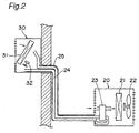
- This air conditioner having humidifying function As an air conditioner having the humidifying function, there has been available one in which the moisture of outside air adsorbed to an adsorbent is desorbed from the adsorbent and supplied to a room as shown in Fig. 2 (Japanese Patent Laid-Open Publication HEI 8-128681).
- This air conditioner having humidifying function as shown in Fig. 2, is equipped with an outdoor unit 20 having an outdoor heat exchanger 21, an outdoor fan 22 and a humidifier 23, and an indoor unit 30 having an indoor heat exchanger 31 and an indoor fan 32, where the humidifier 23 of the outdoor unit 20 and the indoor unit 30 are connected to each other by humidified-air transportation piping 25.
- the humidifier 23 In the thus structured air conditioner having humidifying function, after part of outside air sucked in by the outdoor fan 22 is passed through the humidifier 23 so that the moisture of the outside air is adsorbed to the adsorbent of the humidifier 23, room air sent from the indoor unit 30 through room-air transportation piping 24 is humidified by using the moisture desorbed from the adsorbent. Then, the humidified air is transported to the indoor unit 30 side through the humidified-air transportation piping 25, by which the room air is humidified.
- an air conditioner having humidifying function equipped with a humidifier for adsorbing moisture of outside air to an adsorbent and desorbing the moisture from the adsorbent and then supplying the moisture to an indoor unit, wherein:
- the humidifier In this air conditioner having humidifying function, by disposing the humidifier on top of the outdoor unit, it is no longer necessary to dispose the humidifier within the outdoor unit in a horizontal array with an outdoor heat exchanger and an outdoor fan, so that the floor space of the outdoor unit does not become large. Also, by disposing the humidifying rotor (for example, disc shaped), which is the adsorbent of the humidifier, so that its axis is aligned generally vertical, the humidifier itself can be made lower in height, compared with a humidifying rotor which is so positioned that its axis is horizontal. Therefore, the humidifier can be compactly installed to the outdoor unit without enlarging the floor space of the outdoor unit.
- the humidifying rotor for example, disc shaped
- the air conditioner further comprises humidified-air transportation piping which extends from the humidifier downward along a side face of the outdoor unit and further extends upward from a lower part of the side face of the outdoor unit so as to be connected to the indoor unit.
- the humidified-air transportation piping extends from the humidifier downward along the side face of the outdoor unit and further extends upward from a lower part of the side face of the outdoor unit so as to be connected to the indoor unit, it becomes possible to set the lowermost point of the humidified-air transportation piping at a lower position at least in a lower part of the side face of the outdoor unit.
- a trap for treating condensed water generated inside the humidified-air transportation piping can be easily installed.
- Fig. 1 is a schematic diagram of an air conditioner having humidifying function according to an embodiment of the invention, where reference numeral 1 denotes an outdoor unit, 2 denotes a humidifier installed on top of the outdoor unit 1, and 3 denotes an indoor unit connected to the outdoor unit 1 through inter-unit piping (not shown) and humidified-air transportation piping 4.
- the humidified-air transportation piping 4 extends from the humidifier 2 downward along a side face la of the outdoor unit 1, and extends upward from a lower part of the side face la of the outdoor unit 1, so as to be connected to the indoor unit 3.
- the humidifier 2 has a disc-shaped humidifying rotor 5, and the humidifying rotor 5 has a body made of zeolite or the like as an adsorbent and is so structured as to let air easily pass therethrough.
- a shaft 6 is fixed to the body of the humidifying rotor 5 so as to pass through the center of the disc shape.
- the disc-shaped humidifying rotor 5 is disposed within a casing 10 of the humidifier 2 so that the shaft 6 becomes generally vertical. Otherwise, the humidifying rotor 5 may be formed into polygonal or other shapes without being limited to disc shape.
- the moisture of outside air taken in from outdoors is adsorbed to the adsorbent of the humidifying rotor 5 while the humidifying rotor 5 is maintained rotating about the shaft 6, and further the adsorbed moisture is desorbed from the humidifying rotor 5.
- moisture is taken in from outside air by the humidifying rotor 5 operating to adsorb and desorb the moisture selectively, and air humidified by the intake moisture is supplied to the indoor unit 3 via the humidified-air transportation piping 4 passing through a wall 12.
- the humidified air is blown into an air flow path (not shown) inside the indoor unit 3.
- the humidified air is blown into the room by using an air flow of the indoor fan 11 of the indoor unit 3.
- the humidifier 2 since the humidifier 2 is placed on top of the outdoor unit 1, the humidifier no longer needs to be placed within the outdoor unit 1 in a horizontal array with unshown outdoor heat exchanger or outdoor fan, so that the floor space of the outdoor unit 1 does not become large. Also, when the humidifying rotor 5 is positioned with both side faces generally horizontal by positioning the humidifying rotor 5 of the humidifier 2 with its shaft 6 generally vertical, the humidifier itself can be made lower in height, compared with a humidifying rotor which is so positioned that its shaft is horizontal (i.e., both side faces are generally vertical). Therefore, the humidifier 2 can be compactly installed to the outdoor unit 1 without enlarging the floor space of the outdoor unit 1.
- the humidified-air transportation piping 4 is allowed to extend from the humidifier 2 downward along the side face la of the outdoor unit and further extend upward from a lower part of the side face la of the outdoor unit 1 so as to be connected to the indoor unit 3.
- the lowermost point of the humidified-air transportation piping 4 it becomes possible to set the lowermost point of the humidified-air transportation piping 4 at a low position at least in a lower part of the side face la of the outdoor unit 1.
- a trap for discharging condensed water generated inside the humidified-air transportation piping 4 (including condensed water derived from the humidifier 2 and the indoor unit 3 side) can be easily installed.
- the humidifier 2 is installed on top of the outdoor unit 1.
- the humidifier may also be provided as one which is positioned on an upper side within the outdoor unit and moreover integrated with the outdoor unit.
- the humidifier by the arrangement that the humidifier is disposed on top of the outdoor unit while the humidifying rotor serving as an adsorbent of the humidifier is so positioned that its axis is aligned generally vertical, the humidifier itself can be made low in height, allowing the humidifier to be installed to the outdoor unit more compactly, compared with a humidifying rotor which is so positioned that its axis is horizontal.
- the humidified-air transportation piping that interconnects the humidifier and the indoor unit extends from the humidifier downward along a side face of the outdoor unit and further extends upward from a lower part of the side face of the outdoor unit so as to be connected to the indoor unit, it becomes possible to set the lowermost point of the humidified-air transportation piping at a low position at least in a lower part of the side face of the outdoor unit, so that the trap for treating condensed water generated inside the humidified-air transportation piping can be easily installed.
Landscapes
- Engineering & Computer Science (AREA)
- Chemical & Material Sciences (AREA)
- Combustion & Propulsion (AREA)
- Mechanical Engineering (AREA)
- General Engineering & Computer Science (AREA)
- Air Humidification (AREA)
- Central Air Conditioning (AREA)
- Devices For Blowing Cold Air, Devices For Blowing Warm Air, And Means For Preventing Water Condensation In Air Conditioning Units (AREA)
Abstract
Description
Claims (2)
- An air conditioner having humidifying function equipped with a humidifier (2) for adsorbing moisture of outside air to an adsorbent and desorbing the moisture from the adsorbent and then supplying the moisture to an indoor unit (3), wherein:the humidifier (2) is disposed on top of the outdoor unit (1); andthe adsorbent of the humidifier (2) is a humidifying rotor (5) which is so disposed that its axis is aligned generally vertical.
- The air conditioner having humidifying function according to Claim 1, further comprising:
humidified-air transportation piping (4) which extends from the humidifier (2) downward along a side face of the outdoor unit (1) and further extends upward from a lower part of the side face of the outdoor unit (1) so as to be connected to the indoor unit (3).
Applications Claiming Priority (3)
| Application Number | Priority Date | Filing Date | Title |
|---|---|---|---|
| JP21208999A JP3430980B2 (en) | 1999-07-27 | 1999-07-27 | Air conditioner with humidification function |
| JP21208999 | 1999-07-27 | ||
| PCT/JP2000/004557 WO2001007838A1 (en) | 1999-07-27 | 2000-07-10 | Air conditioner with humidifying function |
Publications (3)
| Publication Number | Publication Date |
|---|---|
| EP1116922A1 true EP1116922A1 (en) | 2001-07-18 |
| EP1116922A4 EP1116922A4 (en) | 2003-04-16 |
| EP1116922B1 EP1116922B1 (en) | 2006-09-13 |
Family
ID=16616702
Family Applications (1)
| Application Number | Title | Priority Date | Filing Date |
|---|---|---|---|
| EP00944343A Expired - Lifetime EP1116922B1 (en) | 1999-07-27 | 2000-07-10 | Air conditioner with humidifying function |
Country Status (7)
| Country | Link |
|---|---|
| EP (1) | EP1116922B1 (en) |
| JP (1) | JP3430980B2 (en) |
| KR (1) | KR100392927B1 (en) |
| CN (1) | CN1158486C (en) |
| ES (1) | ES2270846T3 (en) |
| PT (1) | PT1116922E (en) |
| WO (1) | WO2001007838A1 (en) |
Cited By (4)
| Publication number | Priority date | Publication date | Assignee | Title |
|---|---|---|---|---|
| WO2003048650A1 (en) * | 2001-12-07 | 2003-06-12 | Daikin Industries, Ltd. | Ventilator and air conditioner |
| EP1679476A1 (en) * | 2004-12-28 | 2006-07-12 | Lg Electronics Inc. | Multi-unit air conditioning system with humidifying function |
| EP1598600A3 (en) * | 2004-05-21 | 2010-04-21 | LG Electronics Inc. | Air conditioning system with humidity adjusting apparatus. |
| RU2525818C2 (en) * | 2012-12-03 | 2014-08-20 | Закрытое акционерное общество "АНТАРЕС Комфорт" | Method of use of atmospheric heat pump in systems of air conditioning in buildings with recovery of heat energy and humidity of exhaust air and device for its implementation |
Families Citing this family (10)
| Publication number | Priority date | Publication date | Assignee | Title |
|---|---|---|---|---|
| JP4547831B2 (en) * | 2001-04-23 | 2010-09-22 | ダイキン工業株式会社 | Air conditioner |
| EP1739366B1 (en) * | 2004-03-31 | 2017-07-05 | Daikin Industries, Ltd. | Air conditioning system |
| JP5127280B2 (en) * | 2007-04-06 | 2013-01-23 | 三菱電機株式会社 | Air conditioner |
| CN104764094B (en) * | 2015-03-26 | 2017-06-06 | 广东美的制冷设备有限公司 | The control method of humidifying air conditioner and humidifying air conditioner |
| CN108709274A (en) * | 2018-04-17 | 2018-10-26 | 青岛海尔空调器有限总公司 | Humidification module |
| CN110388712B (en) * | 2018-04-17 | 2021-07-23 | 青岛海尔空调器有限总公司 | Humidifying module |
| CN108518761B (en) * | 2018-04-17 | 2023-04-07 | 青岛海尔空调器有限总公司 | Air conditioner |
| CN112268316A (en) * | 2020-09-08 | 2021-01-26 | 珠海格力电器股份有限公司 | Anhydrous humidifying air conditioner indoor unit and control method thereof |
| CN115200082A (en) * | 2021-04-14 | 2022-10-18 | 宁波奥克斯电气股份有限公司 | Air conditioner with waste heat recovery function |
| CN115164397A (en) * | 2022-07-20 | 2022-10-11 | 珠海格力节能环保制冷技术研究中心有限公司 | Humidifying structure and air conditioner having the same |
Family Cites Families (8)
| Publication number | Priority date | Publication date | Assignee | Title |
|---|---|---|---|---|
| JPS61291845A (en) * | 1985-06-18 | 1986-12-22 | P S Kankyo Giken Kk | Humidity controller |
| JP3132940B2 (en) * | 1993-03-02 | 2001-02-05 | 松下電器産業株式会社 | Air conditioner with humidification function |
| JP3148528B2 (en) * | 1994-07-22 | 2001-03-19 | 三洋電機株式会社 | Dehumidifying and drying equipment |
| JP3157994B2 (en) * | 1994-10-28 | 2001-04-23 | シャープ株式会社 | Air conditioner with humidification function |
| JPH08178362A (en) * | 1994-12-27 | 1996-07-12 | Matsushita Electric Ind Co Ltd | Air conditioner |
| JP2989513B2 (en) * | 1995-04-03 | 1999-12-13 | シャープ株式会社 | Air conditioner with dehumidification function |
| TW343264B (en) * | 1996-07-30 | 1998-10-21 | Sharp Kk | Air conditioner having a humidifying function |
| KR100352430B1 (en) * | 2000-06-12 | 2002-09-16 | 엘지전자 주식회사 | air-wnditional system and air-wnditional control methode having both indoors dehumidificalion system and indoors humidificatian system |
-
1999
- 1999-07-27 JP JP21208999A patent/JP3430980B2/en not_active Expired - Fee Related
-
2000
- 2000-07-10 EP EP00944343A patent/EP1116922B1/en not_active Expired - Lifetime
- 2000-07-10 CN CNB008015287A patent/CN1158486C/en not_active Expired - Lifetime
- 2000-07-10 KR KR10-2001-7003847A patent/KR100392927B1/en not_active Expired - Lifetime
- 2000-07-10 ES ES00944343T patent/ES2270846T3/en not_active Expired - Lifetime
- 2000-07-10 PT PT00944343T patent/PT1116922E/en unknown
- 2000-07-10 WO PCT/JP2000/004557 patent/WO2001007838A1/en not_active Ceased
Cited By (5)
| Publication number | Priority date | Publication date | Assignee | Title |
|---|---|---|---|---|
| WO2003048650A1 (en) * | 2001-12-07 | 2003-06-12 | Daikin Industries, Ltd. | Ventilator and air conditioner |
| CN100425920C (en) * | 2001-12-07 | 2008-10-15 | 大金工业株式会社 | Ventilator and air conditioner |
| EP1598600A3 (en) * | 2004-05-21 | 2010-04-21 | LG Electronics Inc. | Air conditioning system with humidity adjusting apparatus. |
| EP1679476A1 (en) * | 2004-12-28 | 2006-07-12 | Lg Electronics Inc. | Multi-unit air conditioning system with humidifying function |
| RU2525818C2 (en) * | 2012-12-03 | 2014-08-20 | Закрытое акционерное общество "АНТАРЕС Комфорт" | Method of use of atmospheric heat pump in systems of air conditioning in buildings with recovery of heat energy and humidity of exhaust air and device for its implementation |
Also Published As
| Publication number | Publication date |
|---|---|
| CN1158486C (en) | 2004-07-21 |
| CN1319171A (en) | 2001-10-24 |
| PT1116922E (en) | 2006-12-29 |
| EP1116922A4 (en) | 2003-04-16 |
| KR100392927B1 (en) | 2003-07-28 |
| WO2001007838A1 (en) | 2001-02-01 |
| EP1116922B1 (en) | 2006-09-13 |
| JP2001041511A (en) | 2001-02-16 |
| ES2270846T3 (en) | 2007-04-16 |
| KR20010075374A (en) | 2001-08-09 |
| JP3430980B2 (en) | 2003-07-28 |
Similar Documents
| Publication | Publication Date | Title |
|---|---|---|
| EP1116922B1 (en) | Air conditioner with humidifying function | |
| EP3056826B1 (en) | Dehumidifier | |
| JP2008249211A (en) | Air conditioner | |
| JP3608548B2 (en) | Ventilator and air conditioner | |
| JP2003314858A (en) | Air conditioner | |
| JP2002098374A (en) | Clean room humidification method and clean room device | |
| JP5931478B2 (en) | Portable dehumidifier | |
| JP2002089902A (en) | Air conditioner | |
| JPH06257805A (en) | Air conditioner with humidifying function | |
| JP2013160471A5 (en) | ||
| EP2116783A2 (en) | Dehumidifier having dehimidifying rotor | |
| KR100598220B1 (en) | Outdoor unit of air conditioner | |
| JP2017044396A (en) | Air conditioner | |
| JP2002089892A (en) | Air conditioner | |
| JP5532099B2 (en) | Air conditioner outdoor unit | |
| WO2024083200A1 (en) | Waterless humidification module and air conditioner | |
| JP2002102642A (en) | Dehumidifier | |
| JP2002089904A (en) | Air conditioner | |
| JP4066984B2 (en) | Oxygen enrichment device and air conditioning device | |
| JP2019184124A (en) | Air conditioner | |
| EP1058064A2 (en) | A method and a device to reduce or avoid formation and smell of mildew in a building | |
| JP2008241212A (en) | Air conditioner | |
| JP2850434B2 (en) | Air conditioner | |
| JP2003214648A (en) | Air conditioner | |
| JP3858914B2 (en) | Ventilator and air conditioner |
Legal Events
| Date | Code | Title | Description |
|---|---|---|---|
| PUAI | Public reference made under article 153(3) epc to a published international application that has entered the european phase |
Free format text: ORIGINAL CODE: 0009012 |
|
| 17P | Request for examination filed |
Effective date: 20010320 |
|
| AK | Designated contracting states |
Kind code of ref document: A1 Designated state(s): AT BE CH CY DE DK ES FI FR GB GR IE IT LI LU MC NL PT SE |
|
| AX | Request for extension of the european patent |
Free format text: AL;LT;LV;MK;RO;SI |
|
| A4 | Supplementary search report drawn up and despatched |
Effective date: 20030227 |
|
| RIC1 | Information provided on ipc code assigned before grant |
Ipc: 7F 24F 6/00 A Ipc: 7F 24F 1/00 B Ipc: 7F 24F 3/14 B Ipc: 7F 24F 6/06 B |
|
| REG | Reference to a national code |
Ref country code: DE Ref legal event code: 8566 |
|
| RBV | Designated contracting states (corrected) |
Designated state(s): BE ES FR GR IT PT |
|
| GRAP | Despatch of communication of intention to grant a patent |
Free format text: ORIGINAL CODE: EPIDOSNIGR1 |
|
| GRAS | Grant fee paid |
Free format text: ORIGINAL CODE: EPIDOSNIGR3 |
|
| GRAA | (expected) grant |
Free format text: ORIGINAL CODE: 0009210 |
|
| AK | Designated contracting states |
Kind code of ref document: B1 Designated state(s): BE ES FR GR IT PT |
|
| PG25 | Lapsed in a contracting state [announced via postgrant information from national office to epo] |
Ref country code: IT Free format text: LAPSE BECAUSE OF FAILURE TO SUBMIT A TRANSLATION OF THE DESCRIPTION OR TO PAY THE FEE WITHIN THE PRESCRIBED TIME-LIMIT;WARNING: LAPSES OF ITALIAN PATENTS WITH EFFECTIVE DATE BEFORE 2007 MAY HAVE OCCURRED AT ANY TIME BEFORE 2007. THE CORRECT EFFECTIVE DATE MAY BE DIFFERENT FROM THE ONE RECORDED. Effective date: 20060913 |
|
| REG | Reference to a national code |
Ref country code: GR Ref legal event code: EP Ref document number: 20060403866 Country of ref document: GR |
|
| REG | Reference to a national code |
Ref country code: PT Ref legal event code: SC4A Free format text: AVAILABILITY OF NATIONAL TRANSLATION Effective date: 20061012 |
|
| ET | Fr: translation filed | ||
| REG | Reference to a national code |
Ref country code: ES Ref legal event code: FG2A Ref document number: 2270846 Country of ref document: ES Kind code of ref document: T3 |
|
| PLBE | No opposition filed within time limit |
Free format text: ORIGINAL CODE: 0009261 |
|
| STAA | Information on the status of an ep patent application or granted ep patent |
Free format text: STATUS: NO OPPOSITION FILED WITHIN TIME LIMIT |
|
| 26N | No opposition filed |
Effective date: 20070614 |
|
| REG | Reference to a national code |
Ref country code: FR Ref legal event code: PLFP Year of fee payment: 17 |
|
| REG | Reference to a national code |
Ref country code: FR Ref legal event code: PLFP Year of fee payment: 18 |
|
| REG | Reference to a national code |
Ref country code: FR Ref legal event code: PLFP Year of fee payment: 19 |
|
| PGFP | Annual fee paid to national office [announced via postgrant information from national office to epo] |
Ref country code: BE Payment date: 20190617 Year of fee payment: 20 Ref country code: GR Payment date: 20190611 Year of fee payment: 20 Ref country code: FR Payment date: 20190619 Year of fee payment: 20 |
|
| PGFP | Annual fee paid to national office [announced via postgrant information from national office to epo] |
Ref country code: PT Payment date: 20190710 Year of fee payment: 20 Ref country code: ES Payment date: 20190802 Year of fee payment: 20 Ref country code: IT Payment date: 20190719 Year of fee payment: 20 |
|
| REG | Reference to a national code |
Ref country code: BE Ref legal event code: MK Effective date: 20200710 |
|
| PG25 | Lapsed in a contracting state [announced via postgrant information from national office to epo] |
Ref country code: PT Free format text: LAPSE BECAUSE OF EXPIRATION OF PROTECTION Effective date: 20200721 |
|
| REG | Reference to a national code |
Ref country code: ES Ref legal event code: FD2A Effective date: 20210111 |
|
| PG25 | Lapsed in a contracting state [announced via postgrant information from national office to epo] |
Ref country code: ES Free format text: LAPSE BECAUSE OF EXPIRATION OF PROTECTION Effective date: 20200711 |