EP1116631A2 - Elektronische Steuervorrichtung für einen Motor in einem Kraftfahrzeug - Google Patents
Elektronische Steuervorrichtung für einen Motor in einem Kraftfahrzeug Download PDFInfo
- Publication number
- EP1116631A2 EP1116631A2 EP00127912A EP00127912A EP1116631A2 EP 1116631 A2 EP1116631 A2 EP 1116631A2 EP 00127912 A EP00127912 A EP 00127912A EP 00127912 A EP00127912 A EP 00127912A EP 1116631 A2 EP1116631 A2 EP 1116631A2
- Authority
- EP
- European Patent Office
- Prior art keywords
- circuit board
- assembly according
- component
- shell
- lower shell
- Prior art date
- Legal status (The legal status is an assumption and is not a legal conclusion. Google has not performed a legal analysis and makes no representation as to the accuracy of the status listed.)
- Withdrawn
Links
- 239000004020 conductor Substances 0.000 claims abstract description 21
- 239000003990 capacitor Substances 0.000 claims description 21
- 238000003780 insertion Methods 0.000 claims description 8
- 230000037431 insertion Effects 0.000 claims description 8
- 229910001369 Brass Inorganic materials 0.000 claims description 6
- 239000010951 brass Substances 0.000 claims description 6
- 229910000831 Steel Inorganic materials 0.000 claims description 4
- 230000006870 function Effects 0.000 claims description 4
- 238000009434 installation Methods 0.000 claims description 4
- 239000010959 steel Substances 0.000 claims description 4
- 230000003287 optical effect Effects 0.000 claims description 3
- 230000005540 biological transmission Effects 0.000 claims description 2
- 238000010276 construction Methods 0.000 claims description 2
- 230000000284 resting effect Effects 0.000 claims description 2
- 230000000712 assembly Effects 0.000 claims 1
- 238000000429 assembly Methods 0.000 claims 1
- 230000007659 motor function Effects 0.000 claims 1
- 238000005553 drilling Methods 0.000 description 4
- 230000001133 acceleration Effects 0.000 description 3
- 230000002457 bidirectional effect Effects 0.000 description 3
- 238000011161 development Methods 0.000 description 3
- 230000018109 developmental process Effects 0.000 description 3
- 238000013461 design Methods 0.000 description 2
- 238000004519 manufacturing process Methods 0.000 description 2
- 238000000034 method Methods 0.000 description 2
- 241000237983 Trochidae Species 0.000 description 1
- 230000004308 accommodation Effects 0.000 description 1
- 230000009286 beneficial effect Effects 0.000 description 1
- 230000008030 elimination Effects 0.000 description 1
- 238000003379 elimination reaction Methods 0.000 description 1
- 230000000149 penetrating effect Effects 0.000 description 1
- 238000003825 pressing Methods 0.000 description 1
- 238000012549 training Methods 0.000 description 1
- 238000004148 unit process Methods 0.000 description 1
Images


Classifications
-
- B—PERFORMING OPERATIONS; TRANSPORTING
- B60—VEHICLES IN GENERAL
- B60R—VEHICLES, VEHICLE FITTINGS, OR VEHICLE PARTS, NOT OTHERWISE PROVIDED FOR
- B60R16/00—Electric or fluid circuits specially adapted for vehicles and not otherwise provided for; Arrangement of elements of electric or fluid circuits specially adapted for vehicles and not otherwise provided for
- B60R16/02—Electric or fluid circuits specially adapted for vehicles and not otherwise provided for; Arrangement of elements of electric or fluid circuits specially adapted for vehicles and not otherwise provided for electric constitutive elements
- B60R16/023—Electric or fluid circuits specially adapted for vehicles and not otherwise provided for; Arrangement of elements of electric or fluid circuits specially adapted for vehicles and not otherwise provided for electric constitutive elements for transmission of signals between vehicle parts or subsystems
- B60R16/0238—Electrical distribution centers
-
- F—MECHANICAL ENGINEERING; LIGHTING; HEATING; WEAPONS; BLASTING
- F02—COMBUSTION ENGINES; HOT-GAS OR COMBUSTION-PRODUCT ENGINE PLANTS
- F02D—CONTROLLING COMBUSTION ENGINES
- F02D41/00—Electrical control of supply of combustible mixture or its constituents
- F02D41/30—Controlling fuel injection
- F02D41/3005—Details not otherwise provided for
-
- F—MECHANICAL ENGINEERING; LIGHTING; HEATING; WEAPONS; BLASTING
- F02—COMBUSTION ENGINES; HOT-GAS OR COMBUSTION-PRODUCT ENGINE PLANTS
- F02D—CONTROLLING COMBUSTION ENGINES
- F02D2400/00—Control systems adapted for specific engine types; Special features of engine control systems not otherwise provided for; Power supply, connectors or cabling for engine control systems
- F02D2400/18—Packaging of the electronic circuit in a casing
-
- F—MECHANICAL ENGINEERING; LIGHTING; HEATING; WEAPONS; BLASTING
- F02—COMBUSTION ENGINES; HOT-GAS OR COMBUSTION-PRODUCT ENGINE PLANTS
- F02D—CONTROLLING COMBUSTION ENGINES
- F02D2400/00—Control systems adapted for specific engine types; Special features of engine control systems not otherwise provided for; Power supply, connectors or cabling for engine control systems
- F02D2400/22—Connectors or cables specially adapted for engine management applications
Definitions
- the invention relates to an electronic control device for an engine in a motor vehicle according to the preamble of claim 1.
- Such a motor vehicle preferably a passenger car, contains in generally a so-called engine control unit.
- the engine control unit in particular values are supplied via the operating parameters of the engine, for example via the respective piston position, the valve position, the ignition point, the temperature various points of the engine etc. These measured values are in the Engine control unit processes and thereby generate control commands that the in the engine Carry out appropriate adjustment or corrective measures.
- Such a motor vehicle also contains so-called central electronics, which in the controls essentially all electrical functions of the motor vehicle. These are for Example the door lock, an anti-theft device, the lighting, Direction indicators, displays for various operating states and the like
- central electronics usually contain a variety of processors, relays and similar components.
- the engine control unit and the Central electronics exchange data in both directions.
- the wiring harness can be electrical conductors and also light conductors contain.
- Such a wiring harness is a relatively bulky and difficult to handle Component. In particular, there is a risk of contact interruptions or Broken conductors due to shaking movements or vibrations of the wiring harness due to the constant negative and positive accelerations of the vehicle.
- the invention has for its object the means for data exchange between to simplify the engine control unit and the central electronics and the risk of mentioned disturbances due to the constant accelerations of the vehicle reduce.
- the solution according to the invention is thus in contrast to the prior art no wiring harness needed. Due to the resulting elimination of wires, the entire arrangement for the electrical connection between the engine control unit and the central electronics much less susceptible to any kind of interference Vibrations and vibrations due to vehicle accelerations. Also the establishment of the electrical connection between the engine control unit and the central electronics in production much easier than in one Cable harness, which usually has to be attached and fastened manually.
- the invention is can be used advantageously in particular in the marine sector in watercraft but can basically be applied to any type of vehicle.
- the engine control unit and the Central electronics connected to each other via a printed circuit board, the previously required wiring harness replaced.
- the circuit board sets one of those Engine control unit and the central electronics represent a mechanically separate part that only is plugged into the two components and the necessary electrical connection between these parts.
- Engine control unit fully integrated in the central electronics, so to speak in these are integrated and form an integral part of the central electronics. Then the separate circuit board is not required, or it is also an integral part of the Central electronics.
- the printed circuit board has conductors on both sides printed. This will allow better use of space and accommodation Larger number of conductor runs with given dimensions of the modules enables.
- the printed circuit board additionally contains Conductor bridges for one or both of the interconnected by the circuit board Components. Such conductor bridges are essential in a printed circuit board easier to manufacture than in a cable harness.
- the printed circuit board contains the printed circuit board additionally optical or acoustic Display means for operating parameters of the vehicle or for alarm functions. This In the second variant of the invention, means can also be applied directly to an outer surface the central electronics.
- a further development of the invention relates to a structural unit for distributing Operating voltages or operating currents from one central point to different Consumers in a motor vehicle, among other things, the tasks of the above printed circuit board between the central electronics and the engine control unit can take over.
- a lower shell is arranged below the circuit board, on its Underside especially large and less prone to failure components like a cylindrical one Capacitor are arranged.
- This solution results in a compact unit for supplying operating voltages or operating currents to the active and passive components of a structural unit, such as relays, control circuits and Fuses.
- this training are for the transmission of various Operating voltages or supply currents from cable connections on the upper shell of the Special bolts are provided, which one into an opening of the one end Upper shell engaging threaded pin and at the other end opposite the Have thread larger foot, which rests on the circuit board's circuit traces.
- the base of the bolt preferably contains a plurality of on its underside separate pins resting on the conductor tracks, each of which is part of the total in take over the bolt of current flowing into it.
- Threaded cables supplying operating voltages using a cable lug and connected to a mother.
- the openings in the upper shell for the threaded pin are preferably Provide bolts with mechanical codes that only put on the respective enable correct cable lug on a threaded pin and a mix-up prevent the cable lugs between the threaded pins.
- Such codes are for example through differently extending elevations or edges on the Upper shell formed in the area surrounding the openings, to which each of the Cable lug is adjusted.
- the threaded pin of the bolt is made of steel and is in pressed in the brass foot. Brass alone is relatively low Torque behavior and usually breaks off at 10 N x m, while by the called two-piece design of the bolt made of brass and steel a torque up to 20 N x m is reached.
- the lower shell is preferably at its edge with holes for screwing the Provide assembly in a box, a space or other environment.
- the Holes contain lead-in chamfers to facilitate insertion into the correct position in the installation space.
- one of the shells is for holding a larger component such as a capacitor with several, over the Distributed circumference of the component, directed perpendicular to the shell plane, radially to Component resilient arms provided, the hooked ends of the upper edge of the Grasp the component.
- a larger component such as a capacitor with several, over the Distributed circumference of the component, directed perpendicular to the shell plane, radially to Component resilient arms provided, the hooked ends of the upper edge of the Grasp the component.
- a larger component such as a capacitor with several, over the Distributed circumference of the component, directed perpendicular to the shell plane, radially to Component resilient arms provided, the hooked ends of the upper edge of the Grasp the component.
- the lower shell contains two holes through which one self-closing, belt-like part is passed through, which from the top of the Bottom shell as a gripping element for manual insertion, positioning and Pulling out the lower shell into or out of a receptacle.
- the belt-like part is formed by a commercially available cable tie.
- At the Bottom of the lower shell is between the two holes from the shell level molded ring or half ring that surrounds the belt-like part and falling of this part through the lower shell into the receptacle for the component prevented.
- the lower shell has several at the edge spaced guide webs, keep the cables away from the edge and a Pinching a cable underneath the lower shell between the Lower shell and an edge of a receptacle receiving the lower shell prevent.
- Figure 1 shows a central electronics 1, an engine control unit 3 and a motor 4.
- a central electronics 1 and the Engine control unit 3 are these two components via a printed circuit board 2 connected to each other, with opposite sides each in the Central electronics 1 and inserted into the engine control unit 3.
- the circuit board 2 is via the bidirectional data bus 5 with the motor 4 for exchanging the data in the described way connected.
- a conventional one can also be used Conductor bundles, for example in the form of a cable harness or flat cables, be provided.
- the central electronics 1 supplies all others via the data bus 6 electrically operated components within the motor vehicle.
- the engine control unit 3 is in the form of a so-called EDC (Electronic Diesel Control) control unit integrated directly into the central electronics 1, for example a printed circuit board 7 of the central electronics 1.
- EDC Electronic Diesel Control
- the circuit board 7 contains lower part below the engine control unit 3 components J7, J2, D1, J16, S3, J17, S4, S1, J6, J9, J10, J5, which are essentially relays, processors and other discrete Represent components.
- the circuit board 7 contains a connector 8 for Diagnostic device. It can be seen that even in this embodiment the previously required wiring harness for the bidirectional data exchange between the Engine control unit 3 and the remaining part of the central electronics 1 are no longer required becomes.
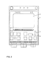
- FIG. 3 shows a perspective view of an embodiment of the Central electronics 1 with the engine control unit 3 according to FIG. 2.
- the engine control unit 3 again shows the engine control unit 3, while the components are in the lower part of Figure 2 are shown.
- FIG. 4 five instruments 8 are additionally shown on the printed circuit board 2 various operating parameters such as engine speed, operating voltages, Temperatures, oil pressure and the like. As well as adjusting means arranged. Execution 4 can also be used in the arrangement of FIG. 2. Instruments 8 would then be on a surface of the central electronics 1.
- FIG. 5 shows an upper shell 9 with a plurality of openings.
- a plurality of contacts 10 inserted from above.
- the contacts 10 are there first loosely with play, ie "floating" in the openings and protrude from the Top of the upper shell 9 out.
- This entire unit from upper shell 9 and Contacts 10 is then in a circuit board 11 arranged below with a Pressed in a large number of conductor tracks or busbars, resulting in a rigid Unit from top shell 9 and circuit board 11 results.
- the lower ones take hold Ends of the contacts 10 into a plurality of holes of the circuit board 14 from only a few are shown. After pressing the contacts 10 into the Circuit board 11, the contacts 10 no longer protrude from the top of the Upper shell 9 emerges, but conclude with this.
- a plurality of electrically conductive bolts 12 are on the circuit board 11 arranged, each of a threaded shaft 13 with a thread M6 or M8 and consist of a foot 14 larger than the thread.
- the foot 14 lies with its underside is electrically conductive on conductor tracks or busbars Circuit board 11 on.
- the threaded shaft 13 engages in openings 15 of the upper shell 9 a.
- Threaded shaft 13 is not a by means of a cable lug and a nut shown power supply cable attached, through which a certain current Conductor tracks or busbars on the circuit board 11 is supplied.
- the Power supply cable comes from a cable harness, not shown, with a Power supply circuit is connected. Below the circuit board 11 is one Lower shell 16 arranged, hanging on the underside of a large capacitor is attached. The three components 9, 11 and 16 are at several attachment points by means of several screws penetrating all these parts to form one structural unit held together.
- FIG. 6 shows a top view of the upper shell 9 without the inserted contacts 10.
- Two attachment points are through holes 17 and 18 in the two shells, while a third attachment point to the recess 19 is formed by a bracket encompassing the parts.
- FIG. 7 shows the upper shell 9 according to FIG. 6 from below.
- the two are recognizable Bores 17, 18 forming attachment points and the third attachment point forming semicircular recess 19.
- FIG. 8 shows a further top view of the upper shell 9 with the following special feature:
- the upper side of the upper shell 9 contains a mechanical one in the area of the openings 15 Coding, which is a mix-up of the cable lugs on the through the openings 15 protruding threaded shafts 13 are placed on prevent.
- the coding consists of a continuous edge or elevation 22 at the three openings 15 has a different course, as can be seen in the lower part of FIG. 8 is.
- the cable lugs are of different shape of the edge at the three openings 15 adapted and can not be mixed up.
- FIG. 9 shows an embodiment of the lower shell 16, in a view from below the Bowl.
- the lower shell 16 contains at its edge bores 23, which for Screwing the entire unit to a box, an installation space or an environment serve.
- the bores 23 are conical with an insertion bevel, that is Continuing upwards in FIG. 9, and thereby automatically find the right one Position of the shell and the component in the installation space.
- the five webs 24 shown serve as cable pinch protection.
- the webs 24 lead cables lying in this area or wire harnesses such that they are kept away from the edge of the lower shell 16 and not, for example, between the edge of the lower shell 16 and an edge clamped on the receptacle for the lower shell, on which the lower shell 16 rests can be.
- the lower shell 16 according to FIG.
- the Bottom shell 16 is usually inserted into a shell-shaped receptacle, wherein the surface visible in FIG. 9 points downwards.
- the lower shell 16 initially has no Gripping element for holding the bowl.
- the bowl now contains two holes 33, 34 between which a ring or half ring 35 is formed. Then one won't Belt-like part shown through the hole 33, through the ring or half ring 35 formed opening and the hole 34 passed through and thus forms on the Top of the lower shell 16 a loop as a gripping element for manual insertion, Pulling out and adjusting the lower shell 16 in one receptacle.
- the ring 35 prevents the belt-like part from following in particular a cable tie falls out below. With the part of the cable tie protruding upwards in shape A loop can then manually remove the entire component or only the lower shell 16 a trough-shaped holder receiving the lower shell 16 is removed, used or adjusted in this.
- Figure 10 shows said bolt 12 with the threaded shaft made of steel 13 and the base made of brass 14.
- the threaded shaft 13 is by means of a Teeth 25 pressed into the foot 14.
- the foot 14 contains one on its underside Variety, for example 25, pin 26, the underside of each on conductor tracks or Busbars of the circuit board 11 rests.
- the over the threaded pin 13th supplied current is thereby distributed to the one part with the brass base 14 existing pin 26.
- Each of these bolts 12 thus carries its own Operating voltage or current, for example positive operating voltage, switched positive operating voltage, energy from the generator etc.
- These currents components such as fuses and relays are then used on the circuit board fed.
- FIG. 11 shows a finished structural unit, which is produced by assembling the individual parts 5 and inserting the components 27. You can see them Upper shell 9, components 27 arranged thereon and inserted into the contacts 10, such as in particular relays and fuses, the lower shell 16, one of the holes 17, 18th to form the attachment point, one of the webs 24 for the cable pinch protection and a threaded shaft 13 for the connection of a power supply cable. On the A large capacitor 28 is attached to the underside of the lower shell 16 Bracket is described with reference to Figures 13 and 14.
- Figure 12 shows the arrangement of Figure 11 from below.
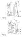
- Figure 13 shows the manner of holding the capacitor 28 on the underside of the Lower shell 16.
- the lower shell 16 contains three over the circumference of the capacitor 28 distributed, radially resilient arms 29, the hook-shaped ends 30 the top of the Grasp capacitor 28.
- This type of secure, form-fitting holder of the capacitor 28 on the lower shell 16 thus brings about a flawless Compensation of larger tolerances in the order of 1-2 mm of the Diameter and the length of the capacitor 28.
- This stable positive Mounting the capacitor 25 on the lower shell 16 is important because of the capacitor is hanging and otherwise slightly down due to its large weight could fall out.
- FIG. 14 shows the arrangement from FIG. 13 without the inserted capacitor 28.
- there are still rigid abutments or stops 32 below the capacitor provided that the axial movement of the capacitor 28 when inserted between limit the arms 29 upon radial deflection of the spring elements 31.
Landscapes
- Engineering & Computer Science (AREA)
- Mechanical Engineering (AREA)
- Chemical & Material Sciences (AREA)
- Combustion & Propulsion (AREA)
- General Engineering & Computer Science (AREA)
- Installation Of Indoor Wiring (AREA)
- Combined Controls Of Internal Combustion Engines (AREA)
- Electrical Control Of Air Or Fuel Supplied To Internal-Combustion Engine (AREA)
Abstract
Description
- Figur 1
- den grundsätzlichen Aufbau einer Steuervorrichtung gemäß der ersten Variante der Erfindung,
- Figur 2
- den Aufbau einer Zentralelektronik mit Motorsteuergerät gemäß der zweiten Variante der Erfindung,
- Figur 3
- eine perspektivische Darstellung der Ausführungsform gemäß Figur 2,
- Figur 4
- eine Ausführungsform der Steuervorrichtung mit Anzeigemitteln,
- Figur 5
- den grundsätzlichen Aufbau einer Baueinheit gemäß der genannten Weiterbildung der Erfindung,
- Figur 6
- die Oberschale von Figur 5 allein,
- Figur 7
- die in Figur 6 dargestellte Oberschale von unten,
- Figur 8
- eine weitere Draufsicht auf die Oberschale gemäß Figur 6 mit einer besonderen konstruktiven Ausführung,
- Figur 9
- eine Ansicht der in Figur 5 dargestellten Unterschale,
- Figur 10
- einen speziellen Bolzen für die Stromzuführung zu den Leiterzügen auf der Schaltungsplatine,
- Figur 11
- die fertige Baueinheit aus Oberschale, Schaltungsplatine, Unterschale und Bauteilen,
- Figur 12
- das komplette Bauteil von Figur 11 von unten,
- Figur 13
- eine spezielle Halterung eines Kondensators in der Anordnung gemäß Figur 11, 12 und
- Figur 14
- die Anordnung gemäß Figur 13 ohne den Kondensator.
- 1
- Zentralelektronik
- 2
- Gedruckte Leiterplatte
- 3
- Motorsteuergerät
- 4
- Motor
- 5
- Datenbus
- 6
- Datenbus
- 7
- Leiterplatte
- 8
- Instrumente
- 9
- Oberschale
- 10
- Kontakte
- 11
- Schaltungsplatine
- 12
- Bolzen
- 13
- Gewindezapfen
- 14
- Fuß
- 15
- Öffnungen
- 16
- Unterschale
- 17
- Bohrung
- 18
- Bohrung
- 19
- Aussparung
- 20
- Öffnungen
- 21
- Bohrung
- 22
- Kante
- 23
- Bohrung
- 24
- Führungsstege
- 25
- Verzahnung
- 26
- Zapfen
- 27
- Bauteile
- 28
- Kondensator
- 29
- Arme
- 30
- hakenförmige Enden
- 31
- Federelemente
- 32
- Anschläge
- 33
- Loch
- 34
- Loch
- 35
- Ring
Claims (26)
- Elektronische Steuervorrichtung für einen Motor in einem Kraftfahrzeug mit einer mehrere elektrisch betriebene Baugruppen steuernden Zentralelektronik und einem die Motorfunktionen steuernden Motorsteuergerät, die elektrisch miteinander verbunden sind, dadurch gekennzeichnet, daß die Zentralelektronik (1) und das Motorsteuergerät (3) über eine gedruckte Leiterplatte (2) miteinander verbunden sind oder daß das Motorsteuergerät (3) vollständig in die Zentralelektronik (1) integriert ist.
- Steuervorrichtung nach Anspruch 1, dadurch gekennzeichnet, daß die Leiterplatte (2) beidseitig mit Leitern bedruckt ist.
- Steuervorrichtung nach Anspruch 1, dadurch gekennzeichnet, daß die Leiterplatte (2) Leiterbrücken für eines oder beide der durch die Leiterplatte (2) miteinander verbundenen Bausteine (1, 3) enthält.
- Steuervorrichtung nach Anspruch 1, dadurch gekennzeichnet, daß die gedruckte Leiterplatte (2) zusätzlich optische oder akustische Anzeigemittel (8) für Betriebsparameter des Fahrzeugs oder für Alarmfunktionen enthält.
- Steuervorrichtung nach Anspruch 1, dadurch gekennzeichnet, daß optische oder akustische Anzeigemittel für Betriebsparameter des Fahrzeugs oder für Alarmfunktionen mit der Zentralelektronik (1) integriert sind.
- Steuervorrichtung nach Anspruch 1, dadurch gekennzeichnet, daß die Leiterplatte (2) ein von der Zentralelektronik (1) und dem Motorsteuergerät (3) getrenntes und in diese Bausteine (1, 3) eingestecktes Bauteil ist.
- Steuervorrichtung nach Anspruch 1, dadurch gekennzeichnet, daß das Motorsteuergerät (3) an dem Motorgehäuse gelagert und die Zentralelektronik (1) über die Leiterplatte (2) auf das Motorsteuergerät (3) aufgesetzt ist.
- Steuervorrichtung nach Anspruch 1, dadurch gekennzeichnet, daß das Motorsteuergerät (3) und die übrigen Bauteile der Zentralelektronik (1) auf einer gemeinsamen Leiterplatte (7) angeordnet sind.
- Steuervorrichtung nach Anspruch 1, gekennzeichnet durch die Anwendung bei Wasserfahrzeugen auf dem Marinebereich.
- Baueinheit zur Verteilung von Betriebsspannungen von einem Zentralpunkt an verschiedene Verbraucher in einem Kraftfahrzeug, dadurch gekennzeichnet, daß eine Vielzahl von zur Aufnahme von Bauteilen (27) vorgesehenen Kontakten (10) durch Öffnungen einer Oberschale (9) hindurchgesteckt und diese Einheit als Ganzes in eine darunter angeordnete Schaltungsplatine (11) eingepreßt ist.
- Baueinheit nach Anspruch 10, dadurch gekennzeichnet, daß unterhalb der Schaltungsplatine (11) eine Unterschale (16) angeordnet ist, auf deren Unterseite gegebenenfalls weitere Bauteile wie ein großer Kondensator (28) befestigt sind.
- Baueinheit nach Anspruch 10, dadurch gekennzeichnet, daß zur Übertragung verschiedener Betriebsspannungen oder Betriebsströmen von Kabelanschlüssen an der Oberschale (9) zu der Schaltungsplatine (11) Bolzen (12) vorgesehen sind, die an einem Ende einen in eine Öffnung (15) der Oberschale (9) eingreifenden Gewindezapfen (13) und am anderen Ende einen gegenüber dem Gewinde größeren Fuß (14) aufweisen, der auf Leiterzügen der Schaltungsplatine (11) aufliegt.
- Baueinheit nach Anspruch 12, dadurch gekennzeichnet, daß der Fuß (14) auf seiner Unterseite mit einer Vielzahl von getrennten, auf den Leiterzügen aufliegenden Zapfen (26) versehen ist.
- Baueinheit nach Anspruch 12, dadurch gekennzeichnet, daß an die durch Öffnungen (15) in der Oberschale (9) hindurchragenden Gewindezapfen (13) Betriebsspannungen führende Leitungen jeweils mittels eines Kabelschuhs und einer Mutter angeschlossen sind.
- Baueinheit nach Anspruch 12, dadurch gekennzeichnet, daß die Öffnungen (15) mit Kodierungen versehen sind, die nur das Aufsetzen des jeweils richtigen Kabelschuhs auf den Gewindezapfen (13) ermöglichen und eine Vertauschung der Kabelschuhe zwischen den Gewindezapfen (13) verhindern.
- Baueinheit nach Anspruch 15, dadurch gekennzeichnet, daß die Kodierung durch unterschiedlich verlaufende Erhebungen oder Kanten (22) an der Oberschale (9) im Umgebungsbereich der Öffnungen (15) gebildet ist.
- Baueinheit nach Anspruch 12, dadurch gekennzeichnet, daß der Gewindezapfen (13) aus Stahl besteht und in den aus Messing bestehenden Fuß (14) eingepreßt ist.
- Baueinheit nach Anspruch 11, dadurch gekennzeichnet, daß die Unterschale (16) an ihrem Rand mit Bohrungen (23) zur Verschraubung der Baueinheit in einer Box, einem Bauraum oder einem sonstigen Umfeld versehen ist.
- Baueinheit nach Anspruch 18, dadurch gekennzeichnet, daß die Bohrungen (23) mit Einführschrägen zur Erleichterung des Einsetzens in die richtige Position in dem Bauraum versehen sind.
- Baueinheit nach Anspruch 11, dadurch gekennzeichnet, daß eine Schale (9, 16) zur Halterung eines größeren Bauteils (28) mit mehreren, über den Umfang des Bauteils verteilten, senkrecht zur Schalenebene gerichteten, radial zum Bauteil (28) federnden Armen (29) versehen ist, die mit hakenförmigen Enden (30) die Oberkante des Bauteils (28) umgreifen.
- Baueinheit nach Anspruch 20, dadurch gekennzeichnet, daß im Bereich des Bauteils (28) an der Oberfläche der Schale (16) mehrere über den Umfang des Bauteils (28) verteilte, radial zum Bauteil (28) federnde Finger (31) vorgesehen sind, die zum Toleranzausgleich in Axialrichtung und in Radialrichtung des Bauteils (28) je auf das Bauteil (28) eine radiale Kraft und eine axiale Kraft ausüben, die das Bauteil (28) gegen die hakenförmigen Enden (30) der federnden Arme (29) drückt.
- Baueinheit nach Anspruch 20, dadurch gekennzeichnet, daß an der Schale (16) mehrere, über den Umfang des Bauteils (28) verteilte starre Widerlager oder Anschläge (32) vorgesehen sind, die die Radialbewegung und die Axialbewegung des Bauteils (28) beim Einsetzen zwischen den federnden Armen (29) begrenzen.
- Baueinheit nach Anspruch 11, dadurch gekennzeichnet, daß die Unterschale (16) zwei Löcher (33, 34) aufweist, durch die ein in sich schließbares, gürtelähnliches Teil hindurchgeführt ist, das von der Oberseite der Unterschale (16) als Greifelement zum manuellen Einsetzen, Positionieren und Herausziehen der Unterschale (16) in eine bzw. aus einer Aufnahme dient.
- Baueinheit nach Anspruch 23, dadurch gekennzeichnet, daß das gürtelähnliche Teil durch einen handelsüblichen Kabelbinder gebildet ist.
- Baueinheit nach Anspruch 23, dadurch gekennzeichnet, daß an der Unterseite der Unterschale (16) zwischen den beiden Löchern (33, 34) ein aus der Schalenebene hervorragender Ring oder Halbring (35) angeformt ist, der das gürtelähnliche Teil umgibt und ein Herunterfallen dieses Teils durch die Unterschale (16) verhindert.
- Baueinheit nach Anspruch 11, dadurch gekennzeichnet, daß die Unterschale (16) am Rand mehrere beabstandete Führungsstege (24) aufweist, die Kabel vom Rand fernhalten und ein Einklemmen eines unterhalb der Unterschale (16) liegenden Kabels zwischen der Unterschale (16) und einer Kante einer die Unterschale (16) aufnehmneden Aufnahme verhindern.
Applications Claiming Priority (4)
| Application Number | Priority Date | Filing Date | Title |
|---|---|---|---|
| DE10001789 | 2000-01-17 | ||
| DE2000101789 DE10001789A1 (de) | 2000-01-17 | 2000-01-17 | Elektronische Steuervorrichtung für einen Motor in einem Kraftfahrzeug |
| DE10047089 | 2000-09-21 | ||
| DE10047089 | 2000-09-21 |
Publications (2)
| Publication Number | Publication Date |
|---|---|
| EP1116631A2 true EP1116631A2 (de) | 2001-07-18 |
| EP1116631A3 EP1116631A3 (de) | 2004-01-07 |
Family
ID=26003893
Family Applications (1)
| Application Number | Title | Priority Date | Filing Date |
|---|---|---|---|
| EP00127912A Withdrawn EP1116631A3 (de) | 2000-01-17 | 2000-12-20 | Elektronische Steuervorrichtung für einen Motor in einem Kraftfahrzeug |
Country Status (1)
| Country | Link |
|---|---|
| EP (1) | EP1116631A3 (de) |
Family Cites Families (5)
| Publication number | Priority date | Publication date | Assignee | Title |
|---|---|---|---|---|
| DE3833146A1 (de) * | 1988-09-29 | 1989-03-02 | Siemens Ag | Verfahren zur herstellung eines steuergeraetes |
| JPH0750767B2 (ja) * | 1989-09-07 | 1995-05-31 | マツダ株式会社 | 金属基板を有する集積回路 |
| FR2733472B1 (fr) * | 1995-04-25 | 1997-07-25 | Valeo Electronique | Platine de servitude pour vehicule, notamment automobile |
| US5667389A (en) * | 1995-10-16 | 1997-09-16 | General Motors Corporation | Automotive vehicle modular buss |
| FR2746736B1 (fr) * | 1996-03-28 | 1998-06-19 | Valeo Electronique | Unite de gestion de vehicule automobile |
-
2000
- 2000-12-20 EP EP00127912A patent/EP1116631A3/de not_active Withdrawn
Non-Patent Citations (1)
| Title |
|---|
| None |
Also Published As
| Publication number | Publication date |
|---|---|
| EP1116631A3 (de) | 2004-01-07 |
Similar Documents
| Publication | Publication Date | Title |
|---|---|---|
| EP0760313A2 (de) | Zentralelektrik für Kraftfahrzeuge | |
| DE4437316C2 (de) | Dezentrale Ein/Ausgabebaugruppe für elektronische Steuerungen | |
| EP0909122A2 (de) | Elektronisches Gerät | |
| DE102016124172A1 (de) | Steckverbinder zur kraftlosen Kontaktierung auf einer Leiterkarte | |
| EP2273623A1 (de) | Leistungsteil für einen Motor eines Flurförderzeugs | |
| DE60007203T2 (de) | Kontaktierungsstruktur für Schaltungen eines Verbindungsblocks | |
| DE102007019805A1 (de) | Kabelkasten | |
| EP0189522A2 (de) | Klemmenplatte für den Anschluss elektrischer Geräte | |
| EP3981046B1 (de) | Modularer leiterkartensteckverbinder | |
| EP1985162A2 (de) | Halter für eine flexible leiterplatte | |
| EP2485347B1 (de) | Vorrichtung zur Positionierung wenigstens eines Rundsteckers | |
| EP3954001A1 (de) | Anordnung von modularen leiterplattensteckverbindern | |
| DE19837314B4 (de) | Vorrichtung für den Masseanschluß elektrischer Komponenten | |
| DE69928755T2 (de) | Armaturenbrett-Montagestruktur | |
| DE29723752U1 (de) | Elektronisches Gerät | |
| DE202011005385U1 (de) | Hochstromkontaktelement für Leiterplatten | |
| DE2418440A1 (de) | Schaltbrettmodul fuer einen integrierten stromkreis | |
| DE19724254A1 (de) | Zentralelektrik mit einer Elektrik- oder Elektronikeinheit, insbesondere für Kraftfahrzeuge | |
| EP1116631A2 (de) | Elektronische Steuervorrichtung für einen Motor in einem Kraftfahrzeug | |
| DE2340773A1 (de) | Uebergabesteckverbindung | |
| DE102021125801A1 (de) | Anschlussdose für ein Daten- oder Kommunikationsnetz | |
| DE19846196A1 (de) | Verbinder für eine Fahrzeug-Batterie | |
| DE102024002546A1 (de) | Klemmvorrichtung | |
| DE102024119035A1 (de) | Elektronisches Steuergerät mit variabler Höhe | |
| EP1396909A1 (de) | Kabelzugentlastung |
Legal Events
| Date | Code | Title | Description |
|---|---|---|---|
| PUAI | Public reference made under article 153(3) epc to a published international application that has entered the european phase |
Free format text: ORIGINAL CODE: 0009012 |
|
| AK | Designated contracting states |
Kind code of ref document: A2 Designated state(s): AT BE CH CY DE DK ES FI FR GB GR IE IT LI LU MC NL PT SE TR |
|
| AX | Request for extension of the european patent |
Free format text: AL;LT;LV;MK;RO;SI |
|
| PUAL | Search report despatched |
Free format text: ORIGINAL CODE: 0009013 |
|
| AK | Designated contracting states |
Kind code of ref document: A3 Designated state(s): AT BE CH CY DE DK ES FI FR GB GR IE IT LI LU MC NL PT SE TR |
|
| AX | Request for extension of the european patent |
Extension state: AL LT LV MK RO SI |
|
| 17P | Request for examination filed |
Effective date: 20040707 |
|
| AKX | Designation fees paid |
Designated state(s): AT BE CH CY DE DK ES FI FR GB GR IE IT LI LU MC NL PT SE TR |
|
| GRAP | Despatch of communication of intention to grant a patent |
Free format text: ORIGINAL CODE: EPIDOSNIGR1 |
|
| STAA | Information on the status of an ep patent application or granted ep patent |
Free format text: STATUS: THE APPLICATION IS DEEMED TO BE WITHDRAWN |
|
| 18D | Application deemed to be withdrawn |
Effective date: 20061123 |