EP1115986B1 - Elektromechanische kraftfahrzeug-bremsvorrichtung - Google Patents
Elektromechanische kraftfahrzeug-bremsvorrichtung Download PDFInfo
- Publication number
- EP1115986B1 EP1115986B1 EP99955710A EP99955710A EP1115986B1 EP 1115986 B1 EP1115986 B1 EP 1115986B1 EP 99955710 A EP99955710 A EP 99955710A EP 99955710 A EP99955710 A EP 99955710A EP 1115986 B1 EP1115986 B1 EP 1115986B1
- Authority
- EP
- European Patent Office
- Prior art keywords
- brake
- piston
- spindle
- housing
- diaphragm
- Prior art date
- Legal status (The legal status is an assumption and is not a legal conclusion. Google has not performed a legal analysis and makes no representation as to the accuracy of the status listed.)
- Expired - Lifetime
Links
- 239000012530 fluid Substances 0.000 claims abstract description 24
- 230000005540 biological transmission Effects 0.000 claims description 11
- 238000005096 rolling process Methods 0.000 claims description 2
- 239000012528 membrane Substances 0.000 abstract description 23
- 210000004379 membrane Anatomy 0.000 description 23
- 238000007789 sealing Methods 0.000 description 11
- 238000005516 engineering process Methods 0.000 description 4
- 238000004519 manufacturing process Methods 0.000 description 4
- 238000012546 transfer Methods 0.000 description 4
- 230000007246 mechanism Effects 0.000 description 3
- 238000005538 encapsulation Methods 0.000 description 2
- 238000007667 floating Methods 0.000 description 2
- 230000002706 hydrostatic effect Effects 0.000 description 2
- 239000007788 liquid Substances 0.000 description 2
- 238000013519 translation Methods 0.000 description 2
- 238000005299 abrasion Methods 0.000 description 1
- 230000001133 acceleration Effects 0.000 description 1
- 230000032683 aging Effects 0.000 description 1
- 230000002457 bidirectional effect Effects 0.000 description 1
- 239000002775 capsule Substances 0.000 description 1
- 230000006835 compression Effects 0.000 description 1
- 238000007906 compression Methods 0.000 description 1
- 238000010276 construction Methods 0.000 description 1
- 230000001419 dependent effect Effects 0.000 description 1
- 238000009826 distribution Methods 0.000 description 1
- 239000000428 dust Substances 0.000 description 1
- 230000005489 elastic deformation Effects 0.000 description 1
- 239000013013 elastic material Substances 0.000 description 1
- 239000000945 filler Substances 0.000 description 1
- 238000003780 insertion Methods 0.000 description 1
- 230000037431 insertion Effects 0.000 description 1
- 238000012423 maintenance Methods 0.000 description 1
- 239000000463 material Substances 0.000 description 1
- 230000035515 penetration Effects 0.000 description 1
- 230000002787 reinforcement Effects 0.000 description 1
- 238000012549 training Methods 0.000 description 1
- 238000004804 winding Methods 0.000 description 1
Images


Classifications
-
- B—PERFORMING OPERATIONS; TRANSPORTING
- B60—VEHICLES IN GENERAL
- B60T—VEHICLE BRAKE CONTROL SYSTEMS OR PARTS THEREOF; BRAKE CONTROL SYSTEMS OR PARTS THEREOF, IN GENERAL; ARRANGEMENT OF BRAKING ELEMENTS ON VEHICLES IN GENERAL; PORTABLE DEVICES FOR PREVENTING UNWANTED MOVEMENT OF VEHICLES; VEHICLE MODIFICATIONS TO FACILITATE COOLING OF BRAKES
- B60T8/00—Arrangements for adjusting wheel-braking force to meet varying vehicular or ground-surface conditions, e.g. limiting or varying distribution of braking force
- B60T8/32—Arrangements for adjusting wheel-braking force to meet varying vehicular or ground-surface conditions, e.g. limiting or varying distribution of braking force responsive to a speed condition, e.g. acceleration or deceleration
- B60T8/321—Arrangements for adjusting wheel-braking force to meet varying vehicular or ground-surface conditions, e.g. limiting or varying distribution of braking force responsive to a speed condition, e.g. acceleration or deceleration deceleration
-
- B—PERFORMING OPERATIONS; TRANSPORTING
- B60—VEHICLES IN GENERAL
- B60T—VEHICLE BRAKE CONTROL SYSTEMS OR PARTS THEREOF; BRAKE CONTROL SYSTEMS OR PARTS THEREOF, IN GENERAL; ARRANGEMENT OF BRAKING ELEMENTS ON VEHICLES IN GENERAL; PORTABLE DEVICES FOR PREVENTING UNWANTED MOVEMENT OF VEHICLES; VEHICLE MODIFICATIONS TO FACILITATE COOLING OF BRAKES
- B60T13/00—Transmitting braking action from initiating means to ultimate brake actuator with power assistance or drive; Brake systems incorporating such transmitting means, e.g. air-pressure brake systems
- B60T13/74—Transmitting braking action from initiating means to ultimate brake actuator with power assistance or drive; Brake systems incorporating such transmitting means, e.g. air-pressure brake systems with electrical assistance or drive
-
- F—MECHANICAL ENGINEERING; LIGHTING; HEATING; WEAPONS; BLASTING
- F15—FLUID-PRESSURE ACTUATORS; HYDRAULICS OR PNEUMATICS IN GENERAL
- F15B—SYSTEMS ACTING BY MEANS OF FLUIDS IN GENERAL; FLUID-PRESSURE ACTUATORS, e.g. SERVOMOTORS; DETAILS OF FLUID-PRESSURE SYSTEMS, NOT OTHERWISE PROVIDED FOR
- F15B7/00—Systems in which the movement produced is definitely related to the output of a volumetric pump; Telemotors
-
- F—MECHANICAL ENGINEERING; LIGHTING; HEATING; WEAPONS; BLASTING
- F16—ENGINEERING ELEMENTS AND UNITS; GENERAL MEASURES FOR PRODUCING AND MAINTAINING EFFECTIVE FUNCTIONING OF MACHINES OR INSTALLATIONS; THERMAL INSULATION IN GENERAL
- F16D—COUPLINGS FOR TRANSMITTING ROTATION; CLUTCHES; BRAKES
- F16D65/00—Parts or details
- F16D65/14—Actuating mechanisms for brakes; Means for initiating operation at a predetermined position
- F16D65/16—Actuating mechanisms for brakes; Means for initiating operation at a predetermined position arranged in or on the brake
- F16D65/18—Actuating mechanisms for brakes; Means for initiating operation at a predetermined position arranged in or on the brake adapted for drawing members together, e.g. for disc brakes
-
- F—MECHANICAL ENGINEERING; LIGHTING; HEATING; WEAPONS; BLASTING
- F16—ENGINEERING ELEMENTS AND UNITS; GENERAL MEASURES FOR PRODUCING AND MAINTAINING EFFECTIVE FUNCTIONING OF MACHINES OR INSTALLATIONS; THERMAL INSULATION IN GENERAL
- F16D—COUPLINGS FOR TRANSMITTING ROTATION; CLUTCHES; BRAKES
- F16D65/00—Parts or details
- F16D65/38—Slack adjusters
- F16D65/40—Slack adjusters mechanical
- F16D65/52—Slack adjusters mechanical self-acting in one direction for adjusting excessive play
- F16D65/56—Slack adjusters mechanical self-acting in one direction for adjusting excessive play with screw-thread and nut
- F16D65/567—Slack adjusters mechanical self-acting in one direction for adjusting excessive play with screw-thread and nut for mounting on a disc brake
-
- F—MECHANICAL ENGINEERING; LIGHTING; HEATING; WEAPONS; BLASTING
- F16—ENGINEERING ELEMENTS AND UNITS; GENERAL MEASURES FOR PRODUCING AND MAINTAINING EFFECTIVE FUNCTIONING OF MACHINES OR INSTALLATIONS; THERMAL INSULATION IN GENERAL
- F16D—COUPLINGS FOR TRANSMITTING ROTATION; CLUTCHES; BRAKES
- F16D66/00—Arrangements for monitoring working conditions, e.g. wear, temperature
- F16D2066/005—Force, torque, stress or strain
-
- F—MECHANICAL ENGINEERING; LIGHTING; HEATING; WEAPONS; BLASTING
- F16—ENGINEERING ELEMENTS AND UNITS; GENERAL MEASURES FOR PRODUCING AND MAINTAINING EFFECTIVE FUNCTIONING OF MACHINES OR INSTALLATIONS; THERMAL INSULATION IN GENERAL
- F16D—COUPLINGS FOR TRANSMITTING ROTATION; CLUTCHES; BRAKES
- F16D2121/00—Type of actuator operation force
- F16D2121/18—Electric or magnetic
- F16D2121/24—Electric or magnetic using motors
-
- F—MECHANICAL ENGINEERING; LIGHTING; HEATING; WEAPONS; BLASTING
- F16—ENGINEERING ELEMENTS AND UNITS; GENERAL MEASURES FOR PRODUCING AND MAINTAINING EFFECTIVE FUNCTIONING OF MACHINES OR INSTALLATIONS; THERMAL INSULATION IN GENERAL
- F16D—COUPLINGS FOR TRANSMITTING ROTATION; CLUTCHES; BRAKES
- F16D2125/00—Components of actuators
- F16D2125/02—Fluid-pressure mechanisms
- F16D2125/10—Plural pistons interacting by fluid pressure, e.g. hydraulic force amplifiers using different sized pistons
-
- F—MECHANICAL ENGINEERING; LIGHTING; HEATING; WEAPONS; BLASTING
- F16—ENGINEERING ELEMENTS AND UNITS; GENERAL MEASURES FOR PRODUCING AND MAINTAINING EFFECTIVE FUNCTIONING OF MACHINES OR INSTALLATIONS; THERMAL INSULATION IN GENERAL
- F16D—COUPLINGS FOR TRANSMITTING ROTATION; CLUTCHES; BRAKES
- F16D2125/00—Components of actuators
- F16D2125/02—Fluid-pressure mechanisms
- F16D2125/14—Fluid-filled flexible members, e.g. enclosed air bladders
-
- F—MECHANICAL ENGINEERING; LIGHTING; HEATING; WEAPONS; BLASTING
- F16—ENGINEERING ELEMENTS AND UNITS; GENERAL MEASURES FOR PRODUCING AND MAINTAINING EFFECTIVE FUNCTIONING OF MACHINES OR INSTALLATIONS; THERMAL INSULATION IN GENERAL
- F16D—COUPLINGS FOR TRANSMITTING ROTATION; CLUTCHES; BRAKES
- F16D2125/00—Components of actuators
- F16D2125/18—Mechanical mechanisms
- F16D2125/20—Mechanical mechanisms converting rotation to linear movement or vice versa
- F16D2125/34—Mechanical mechanisms converting rotation to linear movement or vice versa acting in the direction of the axis of rotation
- F16D2125/40—Screw-and-nut
Definitions
- the invention relates to an electromechanical motor vehicle braking device according to claim 1.
- DE 196 15 186 C1 is a motor vehicle braking device known, one on each wheel on the caliper of the wheel has mounted electromechanical wheel brake actuator, which is a spindle driven in the axial direction and contains an electric motor.
- the rotor of the electric motor is formed as a spindle nut of a spindle gear, which Rotary movement of the rotor in a linear movement of the spindle implements.
- the axial force of the spindle is determined by a mechanical one Translation multiplied and on a piston of a wheel brake cylinder transfer.
- DE 196 29 936 A1 describes an electromechanical braking device described in which an adjustment by a automatic mechanism happens.
- a lever mechanism is provided on the axial force of a spindle rod acts on the input side and the output side on the pressure plate of a transmitter part the adjusting device acts. Due to punctiform Load points on the lever can have high specific surface pressures on the supports and abutments of the lever rods arise, which the use of high quality materials for the Lever bars and bearings require.
- the invention has for its object a motor vehicle braking device to create that despite simple self-adjustment with great compactness and ease of maintenance ensure simple manufacturing and assembly technology can.
- An electromechanical motor vehicle braking device with the first two sub-features of claim 1 and with one the braking force-boosting hydraulic transmission device between the spindle drive and the brake piston known from DE 195 29 664 A1.
- US-A-5 155 997 is a linear transmission actuator known with a liquid translation device, in particular to avoid leakage losses incompressible liquid in a closed capsule elastic material is included.
- the wheel brake actuator 1 contains a braking device 1 for a motor vehicle four brakes 2, each a brake disc 3 and one Actuating device in the form of a wheel brake actuator 4 include.
- the wheel brake actuators 4 each have an associated one Brake caliper 5 integrated, i.e. with him to a unit summarized.
- the brake caliper 5 is designed as a floating caliper.
- About brake pads 6 is when the wheel brake actuator 4 each exerted a braking torque on the brake disc 3.
- Each wheel brake actuator 4 has power and control electronics 8 by an associated control unit 9 with Control signals, for example for the set torque of one more descriptive wheel brake actuator motor, is supplied and to the Control unit 9 feedback values, for example via the actual torque of the wheel brake actuator motor.
- the power and control electronics 8 receives from the wheel brake actuator 4 also feedback values, for example via the Engine speed or the engine rotation angle of the wheel brake actuator motor or the contact pressure of the brake pads.
- the target sizes For each wheel brake actuator the control unit 9 determined from measured variables supplied by various sensors be, for example a force sensor 10 and a Travel sensor 12 with which a pedal force simulator 13 is provided is actuated by the brake pedal 14 of the motor vehicle becomes.
- the pedal force simulator 13 continues the movement of the Brake pedals 14, i.e. the one exercised by the driver as usual Force and the pedal travel, into electrical signals to the Control unit 9 are supplied and setpoints for the brakes 2, especially for vehicle deceleration and that on the Torque or braking torque to be applied.
- To calculate the setpoints in the event of an or driving stability regulations are from the control unit 9 further sensor signals, for example lateral acceleration or yaw rate and wheel speeds, evaluated.
- the brake device 1 has two brake circuits 16 and 17, on the front and rear axles of the motor vehicle are divided. An alternatively possible diagonal brake circuit division only differs from this by changing the assignment of the wheel brake units to the Control devices and power supplies.
- Each brake circuit 16, 17 has its own control unit 9 and its own Energy supply in the form of a battery bat. 1 or Bat. 2.
- the power supplies and the control units can must be housed in one housing but then be functionally separated from each other.
- Supply lines are heavily lined in FIG. 1 and not provided with arrows; Control lines are weakly lined drawn in and with arrows corresponding to the direction of signal flow Mistake.
- the two control units 9 working independently of one another can communicate with each other via a bidirectional signal line communicate and thereby the failure of a brake circuit 16 or 17 in the other brake circuit and if necessary take appropriate emergency measures.
- the braking system can too a third control unit - not shown here - the monitors the two brake circuit control units as supervisor, can be added.
- a wheel brake actuator is directly on a brake caliper housing 18 mounted.
- This has a cylindrical bore 19, in which a displaceable brake piston 20 is guided becomes.
- the brake piston 20 presses on a first plate-shaped Brake pad carrier 21 with an inner brake pad 23 and due to the floating mounting of the brake caliper with the same Force on a second plate-shaped brake pad carrier 22 with an outer brake pad 24.
- the brake pads are on pressed a brake disc 11 and produce in known per se Way due to the friction between the brake pads 23 and 24 and the brake disc 11 a braking torque, which via a holder, not shown here, to the motor vehicle is transmitted and leads to braking.
- a bellows-shaped Dust protection seal 25 prevents the ingress of Dirt, moisture and surface abrasion in the cylindrical Hole 19.
- control and power electronics 8 controllable electric motor 27, for example in the form of a electronically commutated DC motor provided here.
- the stator of the electric motor 27 consists of a Stand part 29, in the grooves windings 30 introduced are.
- the stand part 29 is fixed to a motor housing 32 connected.
- the rotor of the electric motor 27 consists of a Spindle nut 34 of a roller screw drive, on the rotor magnets 35 are applied.
- the roller screw drive sets the Rotational movement of the spindle nut 34 in a longitudinal movement of a Spindle 36 um. Accordingly, the engine torque in an axial force of the spindle 36 is converted. Structure and functionality of roller screw drives are known (see e.g. Publication RGT by INA Lineartechnik oHG).
- the spindle nut 34 mounted on bearings, in the embodiment on an angular contact ball bearing 38 and a radial cylindrical roller bearing 39.
- the axial force of the spindle 36 is in the roller screw drive transferred to the spindle nut 34 and over the angular contact ball bearing 38 in one with the motor housing 32 connected, housing bottom 40 initiated.
- the axial force of the spindle 36 acts on a spindle piston 42 which is in an axial cylindrical bore 37 of the housing base 45 of the brake caliper housing 18 is guided.
- the right End face of the spindle piston 42 d. H. its the spindle 36 opposite side, acts on a fluid volume 43, which in a deformable membrane 44 and thus sealed is completely separated from the environment.
- the membrane 44 is bag-like or sack-like and on the outer circumference of the spindle piston 42 attached pressure-tight.
- the fluid volume 43 is based on one, the spindle piston 42 facing end face radially outside on one Housing bottom 45 of the brake caliper housing 18 and on the other, the end facing away from the spindle piston 42 on an in from the brake caliper housing 18 fixed pressure plate 46, the Cross section is significantly larger than that of the membrane fill opening enclosed spindle piston 42.
- the fluid volume 43 forms together with the enclosing ones and supporting parts 44, 45, 42 and 46 a fluid transmission 42-46, which is extremely efficient and almost works without wear. Due to the flat application of force and power transfer become problems with excessive surface pressure and reliable with asymmetrical force distributions avoided.
- the membrane encapsulation causes an aging of the Fluids by penetration in particular of moisture and Dirt is avoided, reducing the properties of the fluid the entire life of the wheel brake actuator is largely unchanged stay.
- a common brake fluid can be used as the fluid or a gel-like fluid can also be used.
- the force multiplied by the fluid transmission 42-46 Spindle 36 is transferred to the pressure plate 46, the one first cone part 50 with an inner tapered Has edge. It is in the brake caliper housing 18 that with the motor housing 32 is fixedly connected, secured against rotation and moves under the influence of the fluid transmission longitudinal force on them Transmitter part 51 too. A first spring 52 is compressed. Is the pressure plate 46 with its first cone part 50 on a corresponding second cone part 54 of the Transmitter part 51, a non-positive connection is created between these two parts. Due to the friction between the two cone parts 50 and 54 are rotated of the transmitter part 51 prevents - as mentioned - the pressure plate 46 can only be displaced in the axial direction. In the pressure plate 46 is a force sensor 55 for measuring the Force, which acts on the pressure plate 46, built. The sensor signal is the 8 of the control and power electronics Wheel brake actuator evaluated.
- the transmitter part 51 and the brake piston 20 are with a Steep thread pair 56 provided which is not self-locking.
- the brake piston 20 is secured by a suitable fuse its end face - d. H. its the inner brake pad 23 facing side - against the first brake pad carrier 21 Secured rotation, for example by not shown here Wells, in the not shown pin of engage the first brake pad carrier 21.
- the brake piston 20 can only move in the axial direction. Because the brake piston 20 and the transmitter part 51 are secured against rotation, the force from the pressure plate 46 via the steep thread pairing 56 on the brake piston 20 and thus on the inside Transfer brake pad 23.
- An elastically deformable piston sealing ring 57 adheres to the brake piston 20 as long as it is Path in the longitudinal direction a predetermined dimension - for example 1 mm - does not exceed.
- the deformation path of the piston sealing ring 57 is dimensioned that with normal clearance by widening the caliper housing 18 and the compression of the brake pads 23, 24 under
- the adhesion limit between the piston sealing ring is influenced by force 57 and the brake piston 20 is not exceeded, the piston sealing ring 57 is only deformed elastically.
- the piston seal ring 57 slides after exceeding the deformation limit a bit on the brake piston 20 and thus compensates for wear on the lining. So that the spindle 36 on returning to theirs regardless of the wear on the rubber Does not fully retract the brake piston 20 again, is the steep thread pairing between the transformer part 51 and the brake piston 20 are not designed to be self-locking.
- the brake piston 20 is held by the piston sealing ring 57.
- a second spring 58 now presses via an axial bearing 59 on the transmitter part 51 and offset this because of non-self-locking pair of steep threads 56 in rotation.
- the Transmitter part 51 migrates in the longitudinal direction due to this rotary movement out of the brake piston 20 until it is over again the cone parts 50, 54 to bear against the pressure plate 46 comes. This compensates for the wear of the brake linings 23; 24, the brake piston 20 is the wear path from the Cylinder bore 19 migrated out in the brake caliper housing 18.
- the piston sealing ring 57 thus does not form together with the self-locking pair of steep threads 56 between the transmitter part 51 and the brake piston 20 and the first and second Springs 52; 58 an adjusting device for balancing of brake pad wear.
- the brake piston 20 pushed back into the brake caliper housing 18 become. This is achieved with a tool that is recessed engages on the face of the brake piston 20 and with which the brake piston 20 is screwed back into the cylinder bore 19 and screwed onto the transmitter part 51 becomes.
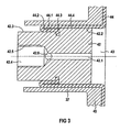
- the spindle piston 42 radially offset on the outer circumference side into a first brake side radially further, only one free from folding Wall part 44.4 of the filling opening against the axial bore 37 of the housing base 45 engaging spindle piston part 42.2 and in a radially narrower one, both on the outer side of the brake housing Membrane part 44.1 and the parallel, folded back or rolled back wall part on the brake piston side 44.2 against the axial bore 37 of the housing base 45 engaging spindle piston part 42.3.
- the diameter of the membrane 44 is in the region of its membrane fill opening folded back or rolled back so that it double-layered on the one hand on the outer surface of the spindle piston 42 rests and on the other hand to the axial bore 37 of the housing bottom 45 nestles.
- the diameter of the spindle piston area 42.2 with the larger one Diameter is advantageously such that it with minimum seal distance slide within the membrane 44 can and the membrane 44 in this area of the fill opening a seal against the axially adjacent area of the folded folded portions of the membrane; this advantageously lubricates the spindle piston 42 ensured by the fluid medium 43, whereby the wear of the membrane 44 in the area of the system to the Spindle piston 42 reduced and at the same time escape of the pressure built up in the membrane 43 in the folded Area is avoidable.
- Membrane 44 with a fluid medium 43 serves an axial filling hole 42.1 in the spindle piston 42 with an outlet opening to the inside of the membrane 45 at one end and with one, optionally by a closure piece 42.6 After the fluid medium has been filled, the loading opening can be closed at their other end.
- the filling can in advantageously only take place when the pressure plate 46, the adjusting device 51 and the still unfilled membrane 44 introduced into the brake caliper housing 18 and the Spindle piston 42 with attached, fastened and folded Filling opening in the axial bore 37 of the housing base 45 is inserted.
- the spindle piston 42 as a separate one Component, preferably after filling the fluid volume, with the rotationally fixed spindle 36 of the spindle drive 34,36, in particular by a screw connection 42.5 in one Insert receptacle 42.4 of the spindle piston 42, connectable.
Landscapes
- Engineering & Computer Science (AREA)
- Mechanical Engineering (AREA)
- General Engineering & Computer Science (AREA)
- Transportation (AREA)
- Physics & Mathematics (AREA)
- Fluid Mechanics (AREA)
- Braking Arrangements (AREA)
Abstract
Description
- FIG 1
- eine schematische Gesamt-Darstellung einer Kraftfahrzeug-Bremsvorrichtung mit elektromechanischen Radbremsaktoren;
- FIG 2
- eine der in der Bremsvorrichtung gemäß FIG 1 verwendeten erfindungsgemäßen Betätigungsvorrichtungen in einer axialen Schnittansicht;
- FIG 3
- einen vergrößerten Detailausschnitt aus FIG 2 im Bereich der Anbindung der Membran an einen elektromechanisch axial verschiebbaren Spindelkolben.
Claims (9)
- Elektromechanische Kraftfahrzeug-Bremsvorrichtung, enthaltendeine von einem Bremspedal (14) über elektrische Leitungen gesteuerte Betätigungsvorrichtung, die als ein an einem Bremssattel (5) eines jeden Rades des Kraftfahrzeuges montierter elektromechanischer Radbremsaktor (4) ausgebildet ist, eine zylindrische Bohrung (19) als Teil des Radbremsaktors (4), in der ein Bremskolben (20) bei einer Bremsbetätigung über einen Spindeltrieb (34,36) axial geführt verschiebbar und gegen einen Bremsbelag (23;25) andrückbar ist,zwischen dem Spindeltrieb (34,36) und dem Bremskolben (20) eine die Bremskraft verstärkende hydraulische Übersetzungseinrichtung in Form eines vollständig gekapselten Fluidgetriebes (42-46) mit einer ein Fluidvolumen (43) einschließenden sackartigen geschlossenen Membran (44),eine, insbesondere flaschenhalsartige, Membran-Einfüllöffnung (44.1;44.2;44.3;44.4), die an Außenumfang eines von dem Spindeltrieb (34,36) axial, insbesondere in einem Gehäuseboden (45) eines Bremssattelgehäuses (18), verschiebbaren Spindelkolbens (42) befestigbar ist.
- Elektromechanische Kraftfahrzeug-Bremsvorrichtung nach Anspruch 1, enthaltendeine Ausbildung der Membran-Einfüllöffnung (44.1;44.2; 44.3;44.4) nach Art eines Falt- bzw. Rollbalges mit einem gegenüber einem radial äußeren bremsgehäuseteilseitigen Membran-Wandteil (44.1) zurückfaltbaren, radial inneren parallelen, axial mit dem Spindelkolben (42) axial bewegbaren spindelkolbenseitigen Wandteil (44.2).
- Elektromechanische Bremsvorrichtung nach Anspruch 2, enthaltendein bremskolbenseitiges, insbesondere formschlüssig am Umfang des Spindelkolbens (42) fixierbares, Befestigungsende (44.3) am freien Ende des bremskolbenseitigen Wandteils (44.2).
- Elektromechanische Kraftfahrzeug-Bremsvorrichtung nach Anspruch 2 und/oder 3, enthaltendeinen außenumfangsseitig radial abgesetzten Spindelkolben (42) mit einem ersten bremsseitigen radial weiteren, nur einen von einer Umknickung freien Wandteil (44.4) der Einfüllöffnung gegen den Gehäuseboden (45) anlegenden Spindelkolbenteil (42.2) und mit einem radial engeren, sowohl den äußeren bremsgehäuseteilseitigen Membranteil (44.1) als auch den dazu parallelen, zurückgefalteten bzw. zurückgerollten bremskolbenseitigen Wandteil (44.2) gegen den Gehäuseboden (45) anlegenden Spindelkolbenteil (42.3).
- Elektromechanische Kraftfahrzeug-Bremsvorrichtung nach zumindest einem der Ansprüche 1 bis 4, enthaltendeine axiale Einfüllbohrung (42.1) für das Fluidvolumen (43) in dem Spindelkolben (42) mit einer spindeltriebseitigen, nach einer Fluid-Beschickung der Membran (44) verschließbaren, Beschickungsöffnung einerseits und einer Ausgangsöffnung zu dem Membran-Innenraum andererseits.
- Elektromechanische Kraftfahrzeug-Bremsvorrichtung nach zumindest einem der Ansprüche 2 bis 5, enthaltendeine nichteinstückige, insbesondere gegenseitig verschraubbare, Verbindung zwischen dem Spindelkolben (42) einerseits und der Spindel (36) des Spindeltriebs (34,36) andererseits.
- Elektromechanische Kraftfahrzeug-Bremsvorrichtung nach zumindest einem der Ansprüche 1 bis 6, enthaltendeine einen Bremsbelagverschleiß selbsttätig ausgleichende Nachstellvorrichtung (52;56;57;58) zwischen dem Fluidgetriebe (42-46) einerseits und dem Bremskolben (20) andererseits.
- Elektromechanische Kraftfahrzeug-Bremsvorrichtung nach Anspruch 7, enthaltendeine Abstützung des Fluidvolumens (43) spindeltriebseitig an dem Gehäuseboden (45) des Bremssattelgehäuses (18) und der membranseitigen Stirnfläche des Spindelkolbens (42) einerseits bzw. bremsseitig an dem Bremskolben (20) andererseits.
- Elektromechanische Kraftfahrzeug-Bremsvorrichtung nach Anspruch 8, enthaltendeine bremsseitige Abstützung des Fluidvolumens (43) an der selbsttätigen Nachstellvorrichtung (51), insbesondere an einer Druckplatte (46) eines Übertragerteus (51) der selbsttätig ausgleichenden Machstellvorrichtung.
Applications Claiming Priority (5)
| Application Number | Priority Date | Filing Date | Title |
|---|---|---|---|
| DE1998143178 DE19843178C1 (de) | 1998-09-21 | 1998-09-21 | Elektromechanische Kraftfahrzeug-Bremsvorrichtung |
| DE19843178 | 1998-09-21 | ||
| DE29914060U DE29914060U1 (de) | 1999-08-12 | 1999-08-12 | Elektromechanische Kraftfahrzeug-Bremsvorrichtung |
| DE29914060U | 1999-08-12 | ||
| PCT/DE1999/002930 WO2000017537A1 (de) | 1998-09-21 | 1999-09-14 | Elektromechanische kraftfahrzeug-bremsvorrichtung |
Publications (2)
| Publication Number | Publication Date |
|---|---|
| EP1115986A1 EP1115986A1 (de) | 2001-07-18 |
| EP1115986B1 true EP1115986B1 (de) | 2003-07-16 |
Family
ID=26048976
Family Applications (1)
| Application Number | Title | Priority Date | Filing Date |
|---|---|---|---|
| EP99955710A Expired - Lifetime EP1115986B1 (de) | 1998-09-21 | 1999-09-14 | Elektromechanische kraftfahrzeug-bremsvorrichtung |
Country Status (3)
| Country | Link |
|---|---|
| EP (1) | EP1115986B1 (de) |
| DE (1) | DE59906306D1 (de) |
| WO (1) | WO2000017537A1 (de) |
Families Citing this family (3)
| Publication number | Priority date | Publication date | Assignee | Title |
|---|---|---|---|---|
| GB2365086B (en) * | 2001-07-17 | 2002-08-28 | Bosch Gmbh Robert | Wheel brake device and method for operation thereof |
| DE102011084206A1 (de) * | 2010-10-12 | 2012-04-12 | Continental Teves Ag & Co. Ohg | Bremsanlage für Kraftfahrzeuge |
| CN116557451B (zh) * | 2023-04-17 | 2025-09-30 | 通富热处理(昆山)有限公司 | 一种刹车盘结构及刹车盘的装配方法 |
Family Cites Families (8)
| Publication number | Priority date | Publication date | Assignee | Title |
|---|---|---|---|---|
| ES521783A0 (es) * | 1983-04-08 | 1984-04-01 | Bendiberica Sa | Sistema de frenado hidroneumatico. |
| DE3525007A1 (de) * | 1985-07-12 | 1987-01-15 | Knorr Bremse Ag | Zuspannzylinder fuer reibungsbremsen |
| US5155997A (en) * | 1990-11-15 | 1992-10-20 | Mcgushion Kevin D | Force-amplifying actuator with capsule-type transmission |
| DE19519308C2 (de) * | 1995-05-26 | 1999-01-21 | Continental Ag | Bremsaktor mit Getriebe |
| DE19529664A1 (de) * | 1995-08-11 | 1997-02-13 | Siemens Ag | Bremsanlage für ein Kraftfahrzeug |
| GB9521868D0 (en) | 1995-10-25 | 1996-01-03 | Lucas Ind Plc | Improvements in electrically-operated disc brake assemblies for vehicles |
| DE19615186C1 (de) | 1996-04-17 | 1997-08-21 | Siemens Ag | Bremsanlage für ein Kraftfahrzeug |
| DE19629936C1 (de) | 1996-07-24 | 1997-11-20 | Siemens Ag | Bremsanlage für ein Kraftfahrzeug |
-
1999
- 1999-09-14 WO PCT/DE1999/002930 patent/WO2000017537A1/de not_active Ceased
- 1999-09-14 DE DE59906306T patent/DE59906306D1/de not_active Expired - Fee Related
- 1999-09-14 EP EP99955710A patent/EP1115986B1/de not_active Expired - Lifetime
Also Published As
| Publication number | Publication date |
|---|---|
| WO2000017537A1 (de) | 2000-03-30 |
| DE59906306D1 (de) | 2003-08-21 |
| EP1115986A1 (de) | 2001-07-18 |
Similar Documents
| Publication | Publication Date | Title |
|---|---|---|
| DE19629936C1 (de) | Bremsanlage für ein Kraftfahrzeug | |
| DE19644441B4 (de) | Elektrisch betätigte Scheibenbremsanordnung für Fahrzeuge | |
| EP1945966B1 (de) | Hydraulische fahrzeugbremse mit integrierter elektromechanisch betätigbarer feststellbremse | |
| DE19511287B4 (de) | Elektromechanische betätigbare Scheibenbremse | |
| EP2473760B1 (de) | Lineareinheit | |
| EP0904221B1 (de) | Bremswertgeber für eine elektrisch gesteuerte und betätigte bremsanlage | |
| DE102016011300B4 (de) | Elektrische Sattelbremse | |
| EP1438519B1 (de) | Betätigungseinheit mit einem kraftwandler für eine scheibenbremse | |
| DE4229042A1 (de) | Bremsbetaetigungs-vorrichtung fuer ein fahrzeug | |
| WO2012104395A2 (de) | Elektromotorisch betreibbares trommelbremsmodul | |
| DE102009038138A1 (de) | Fahrzeugbremse, insbesondere kombinierte Fahrzeugbremse mit elektromechanisch betätigbarer Feststellbremse | |
| DE102011106626A1 (de) | Hochdynamischer Kurzbauantrieb | |
| DE69803703T2 (de) | Betätigungsvorrichtung mit flexiblem element sowie bremssattel mit einer solchen betätigungsvorrichtung | |
| DE19529791A1 (de) | Bremsaktor mit Hydraulikgetriebe | |
| EP2931573A1 (de) | Bremseinheit für ein fahrzeug und fahrzeug mit einer derartigen bremseinheit | |
| DE102017008196A1 (de) | Trommelbremse mit einem elektromechanisch-hydraulischen Bremsaktuator | |
| EP1332300A2 (de) | Elektromechanisch betätigbare scheibenbremse | |
| DE19529664A1 (de) | Bremsanlage für ein Kraftfahrzeug | |
| DE112020006393T5 (de) | Scheibenbremse | |
| WO2011157697A1 (de) | Scheibenbremse in hydraulischer selbstverstärkender bauart mit nachstelleinrichtung | |
| DE19843178C1 (de) | Elektromechanische Kraftfahrzeug-Bremsvorrichtung | |
| DE29914060U1 (de) | Elektromechanische Kraftfahrzeug-Bremsvorrichtung | |
| DE2519836C2 (de) | Hydraulischer Bremskraftverstärker | |
| EP1115986A1 (de) | Elektromechanische kraftfahrzeug-bremsvorrichtung | |
| WO2022012722A1 (de) | Elektromechanische bremsvorrichtung |
Legal Events
| Date | Code | Title | Description |
|---|---|---|---|
| PUAI | Public reference made under article 153(3) epc to a published international application that has entered the european phase |
Free format text: ORIGINAL CODE: 0009012 |
|
| 17P | Request for examination filed |
Effective date: 20010227 |
|
| AK | Designated contracting states |
Kind code of ref document: A1 Designated state(s): AT BE CH CY DE DK ES FI FR GB GR IE IT LI LU MC NL PT SE |
|
| GRAH | Despatch of communication of intention to grant a patent |
Free format text: ORIGINAL CODE: EPIDOS IGRA |
|
| GRAH | Despatch of communication of intention to grant a patent |
Free format text: ORIGINAL CODE: EPIDOS IGRA |
|
| GRAA | (expected) grant |
Free format text: ORIGINAL CODE: 0009210 |
|
| AK | Designated contracting states |
Designated state(s): DE FR GB |
|
| REG | Reference to a national code |
Ref country code: GB Ref legal event code: FG4D Free format text: NOT ENGLISH |
|
| GBT | Gb: translation of ep patent filed (gb section 77(6)(a)/1977) |
Effective date: 20030716 |
|
| REG | Reference to a national code |
Ref country code: IE Ref legal event code: FG4D Free format text: GERMAN |
|
| REF | Corresponds to: |
Ref document number: 59906306 Country of ref document: DE Date of ref document: 20030821 Kind code of ref document: P |
|
| REG | Reference to a national code |
Ref country code: IE Ref legal event code: FD4D |
|
| ET | Fr: translation filed | ||
| PLBE | No opposition filed within time limit |
Free format text: ORIGINAL CODE: 0009261 |
|
| STAA | Information on the status of an ep patent application or granted ep patent |
Free format text: STATUS: NO OPPOSITION FILED WITHIN TIME LIMIT |
|
| 26N | No opposition filed |
Effective date: 20040419 |
|
| PGFP | Annual fee paid to national office [announced via postgrant information from national office to epo] |
Ref country code: FR Payment date: 20080904 Year of fee payment: 10 |
|
| PGFP | Annual fee paid to national office [announced via postgrant information from national office to epo] |
Ref country code: GB Payment date: 20080902 Year of fee payment: 10 |
|
| PGFP | Annual fee paid to national office [announced via postgrant information from national office to epo] |
Ref country code: DE Payment date: 20080828 Year of fee payment: 10 |
|
| GBPC | Gb: european patent ceased through non-payment of renewal fee |
Effective date: 20090914 |
|
| REG | Reference to a national code |
Ref country code: FR Ref legal event code: ST Effective date: 20100531 |
|
| PG25 | Lapsed in a contracting state [announced via postgrant information from national office to epo] |
Ref country code: FR Free format text: LAPSE BECAUSE OF NON-PAYMENT OF DUE FEES Effective date: 20090930 Ref country code: DE Free format text: LAPSE BECAUSE OF NON-PAYMENT OF DUE FEES Effective date: 20100401 |
|
| PG25 | Lapsed in a contracting state [announced via postgrant information from national office to epo] |
Ref country code: GB Free format text: LAPSE BECAUSE OF NON-PAYMENT OF DUE FEES Effective date: 20090914 |
|
| REG | Reference to a national code |
Ref country code: FR Ref legal event code: TP |