EP1115507B1 - Detection de presence multiple d'objets dans une machine de tri - Google Patents
Detection de presence multiple d'objets dans une machine de tri Download PDFInfo
- Publication number
- EP1115507B1 EP1115507B1 EP99942984A EP99942984A EP1115507B1 EP 1115507 B1 EP1115507 B1 EP 1115507B1 EP 99942984 A EP99942984 A EP 99942984A EP 99942984 A EP99942984 A EP 99942984A EP 1115507 B1 EP1115507 B1 EP 1115507B1
- Authority
- EP
- European Patent Office
- Prior art keywords
- buckets
- objects
- images
- path
- upstream
- Prior art date
- Legal status (The legal status is an assumption and is not a legal conclusion. Google has not performed a legal analysis and makes no representation as to the accuracy of the status listed.)
- Expired - Lifetime
Links
- 238000000034 method Methods 0.000 title claims abstract description 24
- 238000011144 upstream manufacturing Methods 0.000 claims description 22
- 238000001514 detection method Methods 0.000 claims description 14
- 238000004458 analytical method Methods 0.000 claims description 7
- 238000000926 separation method Methods 0.000 claims description 4
- 230000000712 assembly Effects 0.000 claims 2
- 238000000429 assembly Methods 0.000 claims 2
- 230000001419 dependent effect Effects 0.000 claims 1
- 241001080024 Telles Species 0.000 description 2
- 238000007373 indentation Methods 0.000 description 2
- 238000004020 luminiscence type Methods 0.000 description 2
- 230000000717 retained effect Effects 0.000 description 2
- 238000012550 audit Methods 0.000 description 1
- 230000015572 biosynthetic process Effects 0.000 description 1
- 230000003247 decreasing effect Effects 0.000 description 1
- 230000007547 defect Effects 0.000 description 1
- 230000003111 delayed effect Effects 0.000 description 1
- 238000010586 diagram Methods 0.000 description 1
- 230000000694 effects Effects 0.000 description 1
- 230000003287 optical effect Effects 0.000 description 1
- 238000009304 pastoral farming Methods 0.000 description 1
- 230000000149 penetrating effect Effects 0.000 description 1
- 230000000284 resting effect Effects 0.000 description 1
- 229920006395 saturated elastomer Polymers 0.000 description 1
- 238000003786 synthesis reaction Methods 0.000 description 1
- 230000001960 triggered effect Effects 0.000 description 1
Images


Classifications
-
- B—PERFORMING OPERATIONS; TRANSPORTING
- B65—CONVEYING; PACKING; STORING; HANDLING THIN OR FILAMENTARY MATERIAL
- B65H—HANDLING THIN OR FILAMENTARY MATERIAL, e.g. SHEETS, WEBS, CABLES
- B65H7/00—Controlling article feeding, separating, pile-advancing, or associated apparatus, to take account of incorrect feeding, absence of articles, or presence of faulty articles
- B65H7/02—Controlling article feeding, separating, pile-advancing, or associated apparatus, to take account of incorrect feeding, absence of articles, or presence of faulty articles by feelers or detectors
- B65H7/06—Controlling article feeding, separating, pile-advancing, or associated apparatus, to take account of incorrect feeding, absence of articles, or presence of faulty articles by feelers or detectors responsive to presence of faulty articles or incorrect separation or feed
- B65H7/12—Controlling article feeding, separating, pile-advancing, or associated apparatus, to take account of incorrect feeding, absence of articles, or presence of faulty articles by feelers or detectors responsive to presence of faulty articles or incorrect separation or feed responsive to double feed or separation
- B65H7/125—Controlling article feeding, separating, pile-advancing, or associated apparatus, to take account of incorrect feeding, absence of articles, or presence of faulty articles by feelers or detectors responsive to presence of faulty articles or incorrect separation or feed responsive to double feed or separation sensing the double feed or separation without contacting the articles
-
- B—PERFORMING OPERATIONS; TRANSPORTING
- B07—SEPARATING SOLIDS FROM SOLIDS; SORTING
- B07C—POSTAL SORTING; SORTING INDIVIDUAL ARTICLES, OR BULK MATERIAL FIT TO BE SORTED PIECE-MEAL, e.g. BY PICKING
- B07C1/00—Measures preceding sorting according to destination
- B07C1/02—Forming articles into a stream; Arranging articles in a stream, e.g. spacing, orientating
- B07C1/04—Forming a stream from a bulk; Controlling the stream, e.g. spacing the articles
-
- B—PERFORMING OPERATIONS; TRANSPORTING
- B07—SEPARATING SOLIDS FROM SOLIDS; SORTING
- B07C—POSTAL SORTING; SORTING INDIVIDUAL ARTICLES, OR BULK MATERIAL FIT TO BE SORTED PIECE-MEAL, e.g. BY PICKING
- B07C3/00—Sorting according to destination
- B07C3/02—Apparatus characterised by the means used for distribution
- B07C3/08—Apparatus characterised by the means used for distribution using arrangements of conveyors
- B07C3/082—In which the objects are carried by transport holders and the transport holders form part of the conveyor belts
-
- B—PERFORMING OPERATIONS; TRANSPORTING
- B65—CONVEYING; PACKING; STORING; HANDLING THIN OR FILAMENTARY MATERIAL
- B65H—HANDLING THIN OR FILAMENTARY MATERIAL, e.g. SHEETS, WEBS, CABLES
- B65H2301/00—Handling processes for sheets or webs
- B65H2301/30—Orientation, displacement, position of the handled material
- B65H2301/32—Orientation of handled material
- B65H2301/321—Standing on edge
Definitions
- the present invention relates to the detection of multiple flat objects in containers conveying said "V" bottom buckets of a sorting.
- the buckets are intended to transport flat objects individually between a loading location and one of a plurality of locations destination along the conveyor line, selected according to the address of the object.
- the unitary distribution of objects in the buckets is made from unstacking.
- the present invention results from a search for solution to this problem, and it consists of a process and a multiple presence detection device flat objects in "V" bottom cups of a sorting machine, downstream of the loading place, the difficulty of this detection being due in particular to fact that the objects being transported resting on their lower edge, this goes down naturally to the bottom corner of the bucket, and that by therefore, in case of multiple objects in the same scoop, their lower edges will have strongly tendency to huddle together, without present continuity solutions between them.
- the lighting is advantageously directed with a relatively grazing incidence compared to objects transported, and downstream upstream relative to direction of movement of the buckets.
- the image obtained according to the process and processed at step (3) thus brings up the lower edge an object in the form of a clear longitudinal strip in a dark background.
- a significant image of multiple presence of objects therefore includes at least one dark intermediate groove between two areas longitudinal clear.
- the heterogeneity of objects treated is not only of order dimensional, but it also relates to nature envelopes for which film material synthetic is used more and more. And in the case transparent envelopes, making step (2) requires special care to make the discrimination between the presence in the buckets of a single fold with such a transparent envelope and the presence of several objects.
- a solution is provided to this problem by providing in addition to lighting in normal light necessary for obtaining images, lighting additional in structured light such as light laser, intended to produce a transverse trace under form of a line on the image of the objects. If the object transported is a fold in an envelope plastic, which may have appeared on the image resulting from normal lighting a dark furrow intermediate between two clear areas, the trace transverse resulting from said additional lighting is not interrupted at the level of said groove dark intermediary, and this indication is essential to the incorrect indication of multiple presence of related objects upon detection on the image of said intermediate groove. If, on the contrary, several objects are transported simultaneously in the same bucket, the transverse trace resulting from said additional lighting presents a interruption at said intermediate groove, confirming the multiple presence indication relating to this last.
- said additional lighting may be emitted in the form a flat brush, advantageously vertical, from from a point below the buckets, and directed towards the up and upstream from the direction of moving the buckets; and it can further be directed with a transverse obliquity to the direction of bucket movement, to increase the legibility on the images of the interruptions of said trace from him, the interruptions then appear said trace as commas successive whose adjacent ends are markedly offset.
- FIGs. 1 and 2 they therefore illustrate a device according to the invention installed in a postal sorting machine for objects dishes with a carousel of buckets serving a plurality of destinations downstream of a loading.
- the machine is schematically represented by a block of three successive buckets G se located directly downstream of a loading station not shown, and moving in the direction of the arrow F.
- the purpose of buckets G is to convey a single object at a time, which is loaded from above and descends until it rests on the bottom by its edge lower, in the immediate vicinity of the same side for all buckets (the right side in Fig. 2) in because of a prior teasing of the objects.
- the unloading of buckets G is ensured by retraction of the bottom which, for this purpose, consists of a pivoting flap V.
- the flap V is quite steep and therefore forms a corner with the rear wall of the bucket relatively closed internal angle or point P. From this made, and as illustrated in the drawing, the objects for the most descend into the buckets until their lower edge T comes to be placed at the deepest in point P. And if inadvertently two objects (or more) were loaded in the same bucket, in the vast majority of cases, their lower slices T will be joined against each other, without no spacing, as shown in the upstream bucket at Fig. 1.
- the separation between sections lower objects in the same bucket is created in making them meet the upstream return means Ra a horizontal track S in an endless band arranged longitudinally under the trajectory of the buckets, directly downstream of their loading station, said path S, when it is crossed by the buckets, penetrating inside of them, at a level slightly above the internal bottom of buckets G in their point P, and scrolling in the same direction as the buckets G, at a speed equal to theirs otherwise slightly higher.
- the device shown in Figs. 1 and 2 includes the aforementioned means for removing the slices lower objects T, and associated means for the realization of images of the separated lower sections during their passage on track S, namely means lighting and a means of taking images.
- the device is mounted in a frame 1 comprising essentially two side plates 1a and 1b. he is arranged longitudinally under the trajectory of buckets G, close to the same side of the latter corresponding to a jogging alignment, and directly downstream of the bucket loading station.
- the endless band arrangement constituting the track S includes two identical sets in parallel, each comprising a belt 2 passing over rollers upstream and downstream, respectively 3 and 4, and a lower roller 5.
- the horizontal upper strands of the two sets constituting the path S, as well as by therefore the upper part of the idler rollers 3 and 4, are at a level slightly higher than that of the inside bottom of buckets G when crossing by them of the two sets, the buckets G presenting openings or indentations of passage 6 at the bottom of their rear wall and their flap V.
- the training of belts 2 is provided by the lower rollers 5 which, for this purpose are mounted on the same transverse axis 7 connected to a drive, not shown.
- the upper rollers 3 and 4 are mounted independently of each other on the plates side 1a and 1b, so that the space upwards between the two sets is completely clear and available for lighting and socket means images.
- the upstream idler rollers 3 have a diameter of 120 mm, track S being raised by approximately 20 mm above the inner corner P of buckets G.
- the lighting means include a source of light 10, visible in FIG. 1 but not shown in Fig. 2 for clarity of the drawing.
- Source 10 is arranged at the top and near the downstream end of the device, centrally between the two sets. It is directed longitudinally upwards and towards upstream, at an angle of about 20 ° with horizontal, on the front part of track S.
- a this illuminated area corresponds to an opening 11 in the bottom of wells G, consisting of indentations in their rear wall and their flap V.
- the gripping means of image 15 advantageously being a camera digital or laser sensor, is placed vertically, just below the illuminated area, the development being made on the plan of the track S. It is triggered by a detector 16 placed slightly in upstream of the lit area to signal the arrival of wells G.
- the detector 16 is advantageously a contactor, actuated at pessage of buckets by a stud attached to the side of these.
- main lighting is associated a lighting in structured light, for example in the form of laser line, from a source 12 placed below from main source 10.
- This light is directed to the same area as the main lighting, at an angle of about 40 ° to the horizontal, but instead of being longitudinal, it presents a certain transverse obliquity, fixed in the example shown at 25 °.
- the skate is advantageously a vertical flat brush, preferably divergent.
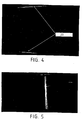
- Figs. 4 to 7 represent the images that we gets with a device like the one that comes to be described.
- the image in Fig. 4 is representative of a bucket empty.
- the two high and low clear lines identified 20 represent both sides of window 11 in the bottom of the bucket, and indicate that the lighting is good worked. The absence of these lines indicates a defect operating such as absence of lighting.
- Fig. 5 corresponds to the presence of a single object in the relevant bucket, appearing under the shape of a single clear transverse band.
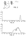
- Fig. 6 corresponds to the presence of two objects appearing as two bands clear transverse, clearly separated by a furrow dark intermediary or border representative of the interval between lower slices of the two objects.
- the image of FIG. 7 corresponds to the case particular of a single object (transparent envelope) whose image resulting from the light source main is not sufficiently differentiated from a multiple presence image to allow a discrimination.
- this discrimination becomes obvious when seen oblique transverse 21 resulting from the lighting additional, because it is not interrupted here in the crossing of the dark intermediate furrow normally indicative of an interval between objects, and differs very clearly from trace 21 of the Fig. 6 resulting similarly from the additional lighting and which is made up of two separated segments, one of the other at the intermediate groove, and whose adjacent ends are clearly offset in the transverse direction.
- each pixel has a level value of gray or luminance between 0 and 255.
- Step 1
- the algorithm achieves a horizontal profile, Fig. 6, and determines if it has a peak, like illustrated in the graph of FIG. 8 where are reported in abscissa the horizontal coordinates of the pixels and in ordered the luminance or gray level values. As shown in Fig. 6, detection begins at mid-height of the image and scrolls down. If at the arrival at the bottom of the image, there was no detection of a peak, this indicates the absence of object in the bucket, or a lighting fault, and the distinction can be made between these two eventualities by providing in the algorithm a high trace detection and low 20 appearing in the image of FIG. 4.
- Step 2
- the previous profile, Fig. 8, allowed to determine whether or not there are any object (s) in the bucket corresponding to the image processed.
- This profile in to optimize the processing time, is advantageously achieved by summing up a few lines horizontal, so it may have variations abrupt due to system noise.
- the diagram in FIG. 9 has a profile with a peak where the first two minima A and B meet the three criteria (a), (b) and (c) and will therefore be retained for further treatment, while minima C will be ignored.
- Step 3
- the first phase of this stage it is searched line by line, from where was realized the profile, the presence of a minimum.
- the area of search is restricted based on the coordinates of the minima and two peaks surrounding it (maxima) found on the starting profile.
- maxima two peaks surrounding it
- the second phase is to determine the point the minimum of lower luminescence, which will be used to determine the starting point for the treatment of next line, exactly above or below depending on the direction of the operation. This point immediately above or below must have him also very low luminance. Otherwise, a penalty is assigned to the area explored. Point lower luminance is also used for detection of a trace 21 resulting from lighting additional in structured light (such as light laser), which detection will be performed at step following treatment.
- structured light such as light laser
- a score is calculated, which determines if the area explored is sufficient significant of a space between objects. To do this, is accumulated the number of weakest points luminescence for which the above condition of difference between maxima beyond the minimum is satisfied. This score is decreased by the number of penalties, and it is normalized with respect to the length of the contour.
- Step 4
- the algorithm stops exploring the contour considered, concluding that there is no interruption of trace 21 at the level of this contour, and that consequently, the latter does not does not correspond to a space between two objects.
- the coordinates of the ends of trace 21 are saved for the next step.
- Step 5
- trace 21 is only found in a parts of the images, and its search is therefore performed only in this part.
Landscapes
- Sorting Of Articles (AREA)
Abstract
Description
- qu'il y ait eu détection de présence multiple dans les deux parties de l'image ;
- que les sillons ou frontières entre objets détectés sur les deux demi-images soient géographiquement proches (par exemple distants de moins de vingt pixels) ;
- que le sillon détecté ne soit pas compris entre les deux extrémités d'une trace 21 détectée.
Claims (15)
- Procédé de détection de présence multiple d'objets dans les godets (G) à fond en "V" d'une machine de tri d'objets plats, dans laquelle les objets sont transportés debout sur leur tranche inférieure dans les godets (G), lequel procédé est caractérisé en ce qu'il comprend les étapes suivantes :(1) faire franchir par les godets (G), en aval du lieu de chargement, une voie (S) orientée selon la trajectoire de ces derniers et constituée par le brin supérieur d'un arrangement en bande sans fin, la voie (S) défilant dans le même sens que les godets et à une vitesse égale ou légèrement supérieure à celle des godets, et passant à l'intérieur des godets lorsque ceux-ci la franchissent, à un niveau légèrement supérieur à celui du point le plus bas (P) du fond intérieur des godets, de telle manière que les objets transportés s'engagent sur la voie (S) par leurs tranches inférieures (T) venant en contact avec le moyen de renvoi amont (Ra) dudit arrangement en bande sans fin en un point en position horaire antérieure à douze heures, (le sens de défilement de ladite voie étant pris comme référence de sens horaire), pour s'élever dans les godets (G) lors du transit sur la voie (S), et être écartées entre elles si elles sont plusieurs dans un même godet ;(2) réaliser des images de la tranche inférieure (T) des objets transportés lors de leur passage sur la voie (S) ; et(3) traiter les images réalisées à l'étape (2) en vue d'obtenir une indication de présence multiple d'objets ou non dans les godets (G) après chaque passage au lieu de chargement.
- Procédé selon la revendication 1, caractérisé en ce que pour réaliser les images à l'étape (2), il est prévu un éclairage dirigé avec une incidence relativement rasante par rapport aux objets transportés, et de l'aval vers l'amont relativement à la direction de déplacement des godets.
- Procédé selon la revendication 1 ou 2, caractérisé en ce que pour réaliser les images à l'étape (2), il est prévu en plus d'un éclairage en lumière normale nécessaire à l'obtention d'images, un éclairage additionnel en lumière structurée, destiné à produire une trace transversale (21) sous forme d'une ligne sur l'image des objets.
- Procédé selon la revendication 3, caractérisé en ce que ledit éclairage additionnel est une source de lumière laser.
- Procédé selon la revendication 3 ou 4, caractérisé en ce que ledit éclairage additionnel est émis sous forme d'un pinceau plat, à partir d'un point au-dessous des godets (G), dirigé vers le haut et vers l'amont par rapport à la direction de déplacement des godets, et avec une obliquité transversale par rapport à la direction de déplacement des godets, pour augmenter la lisibilité sur les images des interruptions de ladite trace (21) issue de lui, les interruptions faisant alors apparaítre ladite trace sous forme de virgules successives- dont les extrémités adjacentes sont nettement décalées transversalement.
- Procédé selon l'une des revendications 1 à 5, caractérisé en ce que l'étape (3) de traitement d'image comprend elle-même les étapes suivantes :détecter une information de présence d'objet dans le godet correspondant à l'image considérée, cette information se présentant sous la forme d'un pic de luminance sur un profil horizontal réalisé sur l'image ;en cas de détection positive, rechercher des minima dans un pic détecté et retenir ceux qui potentiellement sont représentatifs d'une séparation entre deux objets ;effectuer un suivi de contour sur l'image considérée à partir des coordonnées d'un minima retenu, et déterminer si ce contour est potentiellement indicateur d'une présence multiple d'objets ;analyser l'ensemble des résultats pour déclarer qu'il y a ou non présence multiple d'objets.
- Procédé selon la revendication précédente, elle-même dépendante de la revendication 4, caractérisé en ce que l'étape (3) de traitement d'image comprend elle-même une étape supplémentaire relative à l'analyse de la trace résultant dudit éclairage additionnel.
- Procédé selon la revendication 6 ou 7, caractérisé en ce qu'à l'étape (3) de traitement d'image, les images considérées sont subdivisées en deux parties soumises chacune au traitement précédant l'analyse finale, la confrontation des résultats concernant les deux parties de l'image étant prise en compte dans l'analyse finale.
- Dispositif pour mettre en oeuvre le procédé selon l'une des revendications précédentes, caractérisé en ce qu'il comprend en combinaison :un arrangement en bande sans fin immédiatement en aval du lieu de chargement des godets (G), dont le brin supérieur forme à partir d'un moyen de renvoi amont (Ra ou 3) une voie orientée (S) selon la trajectoire des godets (G), laquelle voie (S) est disposée de telle manière que lorsqu'elle est franchie par les godets (G), elle pénètre à l'intérieur de ceux-ci, à un niveau légèrement au-dessus du point le plus bas (P) du fond intérieur des godets, et défile dans le même sens que les godets (G) et à une vitesse égale ou légèrement supérieure à celle des godets ;des moyens de réalisation d'images de la tranche inférieure (T) des objets transportés lors de leur passage sur ladite voie (S) ; etdes moyens de traitement d'images pour détecter la présence multiple d'objets dans les godets (G).
- Dispositif selon la revendication 9, caractérisé en ce que ledit arrangement en bande sans fin comprend entre les parois latérales (la, 1b) d'un bâti (1), deux ensembles identiques en parallèle, chacun comportant une courroie (2) passant sur des galets de renvoi amont et aval (3, 4), les brins supérieurs horizontaux dans les deux ensembles formant la voie (S).
- Dispositif selon la revendication 10, caractérisé en ce que chaque ensemble dudit arrangement en bande sans fin comprend un galet inférieur (5) qui est moteur, les deux galets (5) étant montés sur un même axe transversal (7) connecté à un moyen d'entraínement, tandis que les galets de renvoi amont et aval (3, 4) sont montés indépendamment les uns des autres sur les parois (la, 1b) du bâti (1).
- Dispositif selon la revendication 10 ou 11, caractérisé en ce que les courroies (2) sont crantées.
- Dispositif selon l'une des revendications 10 à 12, caractérisé en ce qu'il comprend une rampe (8) d'accès des objets sur chaque galet de renvoi amont (3).
- Dispositif selon l'une des revendications 10 à 13, caractérisé en ce qu'il comprend une source de lumière (10) disposée dans le haut et prés de l'extrémité aval du bâti (1), et une source de lumière structurée (12) placée au-dessous de la source principale (10), toutes deux dirigées de bas en haut et d'aval en amont, vers une même zone de la voie (S).
- Dispositif selon la revendication 14, caractérisé en ce que la source (12) émet de la lumière laser, sous la forme d'un pinceau plat sensiblement vertical et oblique transversalement.
Applications Claiming Priority (3)
| Application Number | Priority Date | Filing Date | Title |
|---|---|---|---|
| FR9811897 | 1998-09-21 | ||
| FR9811897A FR2783442B1 (fr) | 1998-09-21 | 1998-09-21 | Procede de detection de presence multiple d'objets dans les godets de convoyage d'une machine de tri et dispositif servant a sa mise en oeuvre |
| PCT/FR1999/002202 WO2000016915A1 (fr) | 1998-09-21 | 1999-09-16 | Detection de presence multiple d'objets dans une machine de tri |
Publications (2)
| Publication Number | Publication Date |
|---|---|
| EP1115507A1 EP1115507A1 (fr) | 2001-07-18 |
| EP1115507B1 true EP1115507B1 (fr) | 2003-05-21 |
Family
ID=9530767
Family Applications (1)
| Application Number | Title | Priority Date | Filing Date |
|---|---|---|---|
| EP99942984A Expired - Lifetime EP1115507B1 (fr) | 1998-09-21 | 1999-09-16 | Detection de presence multiple d'objets dans une machine de tri |
Country Status (4)
| Country | Link |
|---|---|
| EP (1) | EP1115507B1 (fr) |
| DE (1) | DE69908155T2 (fr) |
| FR (1) | FR2783442B1 (fr) |
| WO (1) | WO2000016915A1 (fr) |
Cited By (2)
| Publication number | Priority date | Publication date | Assignee | Title |
|---|---|---|---|---|
| DE102010012951A1 (de) | 2010-03-26 | 2011-09-29 | Siemens Aktiengesellschaft | Vorrichtung und Verfahren zum Erzeugen eines Abbilds von einem bewegten Gegenstand |
| DE102010014105A1 (de) | 2010-04-07 | 2011-10-13 | Siemens Aktiengesellschaft | Verfahren und Vorrichtung zum Vermessen von Gegenständen während des Transports |
Families Citing this family (2)
| Publication number | Priority date | Publication date | Assignee | Title |
|---|---|---|---|---|
| US7809158B2 (en) | 2005-05-02 | 2010-10-05 | Siemens Industry, Inc. | Method and apparatus for detecting doubles in a singulated stream of flat articles |
| EP2409786B1 (fr) * | 2010-07-21 | 2013-02-13 | SELEX ELSAG S.p.A. | Dispositif singulateur pour objets revêtus d'un film transparent |
Family Cites Families (3)
| Publication number | Priority date | Publication date | Assignee | Title |
|---|---|---|---|---|
| US5331151A (en) * | 1993-01-25 | 1994-07-19 | Pressco Technology, Inc. | Multiple envelope detector |
| US5718321A (en) * | 1993-07-14 | 1998-02-17 | Siemens Aktiengesellschaft | Sorting apparatus for mail and the like |
| FR2738506B1 (fr) * | 1995-09-08 | 1997-10-17 | Alcatel Postal Automation Syst | Dispositif et procede de tri d'articles de courrier utilisant des receptacles tampon en sortie de tri |
-
1998
- 1998-09-21 FR FR9811897A patent/FR2783442B1/fr not_active Expired - Fee Related
-
1999
- 1999-09-16 DE DE69908155T patent/DE69908155T2/de not_active Expired - Fee Related
- 1999-09-16 EP EP99942984A patent/EP1115507B1/fr not_active Expired - Lifetime
- 1999-09-16 WO PCT/FR1999/002202 patent/WO2000016915A1/fr active IP Right Grant
Cited By (3)
| Publication number | Priority date | Publication date | Assignee | Title |
|---|---|---|---|---|
| DE102010012951A1 (de) | 2010-03-26 | 2011-09-29 | Siemens Aktiengesellschaft | Vorrichtung und Verfahren zum Erzeugen eines Abbilds von einem bewegten Gegenstand |
| DE102010014105A1 (de) | 2010-04-07 | 2011-10-13 | Siemens Aktiengesellschaft | Verfahren und Vorrichtung zum Vermessen von Gegenständen während des Transports |
| WO2011124583A1 (fr) | 2010-04-07 | 2011-10-13 | Siemens Aktiengesellschaft | Procédé et dispositif pour le transport régulé de plusieurs objets |
Also Published As
| Publication number | Publication date |
|---|---|
| WO2000016915A1 (fr) | 2000-03-30 |
| FR2783442A1 (fr) | 2000-03-24 |
| DE69908155D1 (de) | 2003-06-26 |
| EP1115507A1 (fr) | 2001-07-18 |
| DE69908155T2 (de) | 2004-03-25 |
| FR2783442B1 (fr) | 2000-11-10 |
Similar Documents
| Publication | Publication Date | Title |
|---|---|---|
| EP3097407B1 (fr) | Procédé et dispositif pour la détection notamment de défauts refractants | |
| EP2459472B1 (fr) | Table d'accumulation d'articles pour une installation de convoyage | |
| EP1583617B1 (fr) | Dispositif de convoyage de produits, notamment de fruits ou legumes, adapte pour effectuer un triage des produits au moins en fonction de leur poids | |
| CA2727666A1 (fr) | Installation de convoyage multivoies | |
| FR2907437A1 (fr) | Table de repartition de bouteilles a l'entree de couloirs a file unique | |
| EP2809600B1 (fr) | Machine de tri d'objets plats sur chant avec détection de prise multiple | |
| WO2001001071A1 (fr) | Procede et dispositif d'analyse en vue du tri automatique de produits tels que des fruits | |
| CA2949877A1 (fr) | Dispositif et procede d'intervention sur ligne de convoyage | |
| EP3233460A1 (fr) | Dispositif et procédé de contrôle de la qualité de boîtes pliables et installation de fabrication comprenant un tel dispositif de contrôle | |
| FR2485232A2 (fr) | Installation pour encourager la restitution de chariots dans un supermarche | |
| EP1115507B1 (fr) | Detection de presence multiple d'objets dans une machine de tri | |
| FR2891168A1 (fr) | Procede pour detecter des envois postaux en prises multiples par analyse de l'image du chant des envois | |
| FR2860581A1 (fr) | Procede et installation pour le controle de qualite en boulangerie | |
| FR2953930A1 (fr) | Dispositif de controle visuel | |
| EP2454178A1 (fr) | Dispositif de dépilage d'objets plats avec détection de la trace des objets dépilés | |
| FR2951444A1 (fr) | Dispositif de formation de lots de produits pour leur chargement dans des receptacles | |
| EP2049418B1 (fr) | Procédé pour contrôler la tension d'une chaîne de carrousel à godets | |
| WO2019239052A2 (fr) | Installation de selection d'objets defilant sur une ligne de transfert | |
| WO2002038474A1 (fr) | Dispositif de mise en defilement continu d'objets a symetrie de revolution - application a l'inspection visuelle et au controle | |
| FR2563340A1 (fr) | Appareil et procede de controle et de tri de recipients en verre | |
| FR2563926A1 (fr) | Machine a deconsigner les bouteilles vides reprises par les magasins a grande surface | |
| FR2748461A1 (fr) | Procede et dispositif pour positionner precisement des produits sur un systeme de transfert en vue d'alimenter un appareil recepteur | |
| WO1993006469A1 (fr) | Procede et dispositif de detection de corps etrangers dans des recipients transparents | |
| EP3366166A1 (fr) | Station d'encaissement d'articles de marchandise configurée pour équiper un magasin de vente au détail | |
| EP0919494A1 (fr) | Procédé et dispositif pour positionner des produits sur un système de transfert, constitué par deux convoyeurs |
Legal Events
| Date | Code | Title | Description |
|---|---|---|---|
| PUAI | Public reference made under article 153(3) epc to a published international application that has entered the european phase |
Free format text: ORIGINAL CODE: 0009012 |
|
| 17P | Request for examination filed |
Effective date: 20010405 |
|
| AK | Designated contracting states |
Kind code of ref document: A1 Designated state(s): AT BE CH CY DE DK ES FI FR GB GR IE IT LI LU MC NL PT SE |
|
| GRAH | Despatch of communication of intention to grant a patent |
Free format text: ORIGINAL CODE: EPIDOS IGRA |
|
| GRAH | Despatch of communication of intention to grant a patent |
Free format text: ORIGINAL CODE: EPIDOS IGRA |
|
| GRAA | (expected) grant |
Free format text: ORIGINAL CODE: 0009210 |
|
| AK | Designated contracting states |
Designated state(s): BE DE ES FR GB IT |
|
| PG25 | Lapsed in a contracting state [announced via postgrant information from national office to epo] |
Ref country code: IT Free format text: LAPSE BECAUSE OF FAILURE TO SUBMIT A TRANSLATION OF THE DESCRIPTION OR TO PAY THE FEE WITHIN THE PRE;WARNING: LAPSES OF ITALIAN PATENTS WITH EFFECTIVE DATE BEFORE 2007 MAY HAVE OCCURRED AT ANY TIME BEFORE 2007. THE CORRECT EFFECTIVE DATE MAY BE DIFFERENT FROM THE ONE RECORDED.SCRIBED TIME-LIMIT Effective date: 20030521 Ref country code: GB Free format text: LAPSE BECAUSE OF FAILURE TO SUBMIT A TRANSLATION OF THE DESCRIPTION OR TO PAY THE FEE WITHIN THE PRESCRIBED TIME-LIMIT Effective date: 20030521 |
|
| REG | Reference to a national code |
Ref country code: GB Ref legal event code: FG4D Free format text: NOT ENGLISH |
|
| REF | Corresponds to: |
Ref document number: 69908155 Country of ref document: DE Date of ref document: 20030626 Kind code of ref document: P |
|
| PG25 | Lapsed in a contracting state [announced via postgrant information from national office to epo] |
Ref country code: ES Free format text: LAPSE BECAUSE OF FAILURE TO SUBMIT A TRANSLATION OF THE DESCRIPTION OR TO PAY THE FEE WITHIN THE PRESCRIBED TIME-LIMIT Effective date: 20030901 |
|
| GBV | Gb: ep patent (uk) treated as always having been void in accordance with gb section 77(7)/1977 [no translation filed] |
Effective date: 20030521 |
|
| PLBE | No opposition filed within time limit |
Free format text: ORIGINAL CODE: 0009261 |
|
| STAA | Information on the status of an ep patent application or granted ep patent |
Free format text: STATUS: NO OPPOSITION FILED WITHIN TIME LIMIT |
|
| 26N | No opposition filed |
Effective date: 20040224 |
|
| PGFP | Annual fee paid to national office [announced via postgrant information from national office to epo] |
Ref country code: DE Payment date: 20081002 Year of fee payment: 10 |
|
| PGFP | Annual fee paid to national office [announced via postgrant information from national office to epo] |
Ref country code: BE Payment date: 20080829 Year of fee payment: 10 |
|
| BERE | Be: lapsed |
Owner name: *LA POSTE Effective date: 20090930 |
|
| PG25 | Lapsed in a contracting state [announced via postgrant information from national office to epo] |
Ref country code: DE Free format text: LAPSE BECAUSE OF NON-PAYMENT OF DUE FEES Effective date: 20100401 |
|
| PG25 | Lapsed in a contracting state [announced via postgrant information from national office to epo] |
Ref country code: BE Free format text: LAPSE BECAUSE OF NON-PAYMENT OF DUE FEES Effective date: 20090930 |
|
| REG | Reference to a national code |
Ref country code: FR Ref legal event code: PLFP Year of fee payment: 18 |
|
| REG | Reference to a national code |
Ref country code: FR Ref legal event code: PLFP Year of fee payment: 19 |
|
| REG | Reference to a national code |
Ref country code: FR Ref legal event code: PLFP Year of fee payment: 20 |
|
| PGFP | Annual fee paid to national office [announced via postgrant information from national office to epo] |
Ref country code: FR Payment date: 20180927 Year of fee payment: 20 |