EP1115196A2 - Motor control device - Google Patents
Motor control device Download PDFInfo
- Publication number
- EP1115196A2 EP1115196A2 EP01100380A EP01100380A EP1115196A2 EP 1115196 A2 EP1115196 A2 EP 1115196A2 EP 01100380 A EP01100380 A EP 01100380A EP 01100380 A EP01100380 A EP 01100380A EP 1115196 A2 EP1115196 A2 EP 1115196A2
- Authority
- EP
- European Patent Office
- Prior art keywords
- axis
- axis current
- voltage
- current command
- command
- Prior art date
- Legal status (The legal status is an assumption and is not a legal conclusion. Google has not performed a legal analysis and makes no representation as to the accuracy of the status listed.)
- Granted
Links
Images



Classifications
-
- H—ELECTRICITY
- H02—GENERATION; CONVERSION OR DISTRIBUTION OF ELECTRIC POWER
- H02P—CONTROL OR REGULATION OF ELECTRIC MOTORS, ELECTRIC GENERATORS OR DYNAMO-ELECTRIC CONVERTERS; CONTROLLING TRANSFORMERS, REACTORS OR CHOKE COILS
- H02P21/00—Arrangements or methods for the control of electric machines by vector control, e.g. by control of field orientation
- H02P21/06—Rotor flux based control involving the use of rotor position or rotor speed sensors
-
- H—ELECTRICITY
- H02—GENERATION; CONVERSION OR DISTRIBUTION OF ELECTRIC POWER
- H02P—CONTROL OR REGULATION OF ELECTRIC MOTORS, ELECTRIC GENERATORS OR DYNAMO-ELECTRIC CONVERTERS; CONTROLLING TRANSFORMERS, REACTORS OR CHOKE COILS
- H02P21/00—Arrangements or methods for the control of electric machines by vector control, e.g. by control of field orientation
- H02P21/0085—Arrangements or methods for the control of electric machines by vector control, e.g. by control of field orientation specially adapted for high speeds, e.g. above nominal speed
- H02P21/0089—Arrangements or methods for the control of electric machines by vector control, e.g. by control of field orientation specially adapted for high speeds, e.g. above nominal speed using field weakening
-
- H—ELECTRICITY
- H02—GENERATION; CONVERSION OR DISTRIBUTION OF ELECTRIC POWER
- H02P—CONTROL OR REGULATION OF ELECTRIC MOTORS, ELECTRIC GENERATORS OR DYNAMO-ELECTRIC CONVERTERS; CONTROLLING TRANSFORMERS, REACTORS OR CHOKE COILS
- H02P25/00—Arrangements or methods for the control of AC motors characterised by the kind of AC motor or by structural details
- H02P25/02—Arrangements or methods for the control of AC motors characterised by the kind of AC motor or by structural details characterised by the kind of motor
- H02P25/08—Reluctance motors
Definitions
- the present invention relates to a motor control device for controlling a permanent magnet reluctance motor.
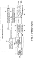
- Fig. 1 illustrates an example of a conventional motor control device with field-weakening control of this kind.
- This control device has a dq axes current command setting unit 11, a d-axis current command correction unit 14, a d-axis current control unit 16, a q-axis current control unit 17, a voltage vector length calculation unit 18, a voltage vector length restriction unit 19, a terminal voltage uniformity control unit 20, and a dq three-phase transformation unit 21. It should be added that in this example of the prior art it is assumed that the permanent magnet reluctance motor is driven under vector control.
- the dq axes current command setting unit 11 inputs the torque command Tref, determining the d-axis current command Idref and q-axis current command Iqref required in order to output this torque.
- the d-axis current command Idref is corrected by the d-axis current command correction unit 14 by adding the d-axis current command correction value ⁇ Idref from the terminal voltage uniformity control unit 20, and this is input to the d-axis current control unit 16.
- the q-axis current command Iqref is input to the q-axis current control unit 17.
- the d-axis current control unit 16 inputs the d-axis current command Idref fed from the d-axis current command correction unit 14 and the d-axis current feedback value Id, and generates a d-axis voltage command Vd in such a manner that the d-axis current feedback value Id tracks the d-axis current command Idref. This is input to the dq three-phase transformation unit 21.
- the q-axis current control unit 17 inputs the q-axis current command Iqref fed from the q-axis current command correction unit 11 and the q-axis current feedback value Iq, and generates a q-axis voltage command Vq in such a manner that the q-axis current feedback value Iq tracks the q-axis current command Iqref. This is input to the dq three-phase transformation unit 21.
- the dq three-phase transformation unit 21 generates the three-phase voltage commands Vu, Vv and Vw on the basis of the d-axis voltage command Vd, the q-axis voltage command Vq and the motor rotor potential ⁇ r, controlling the motor by way of a voltage transformer not illustrated in the drawing in order to achieve this.
- the voltage vector length calculation unit 18 inputs the dq axes voltage commands Vd and Vq and calculates the voltage vector length (absolute voltage value) V1.
- the voltage vector length restriction unit 19 inputs the resultant voltage vector length V1 and the inverter input direct-current voltage Vdc, and determines the restricted voltage vector restriction length Vllim.
- the terminal voltage uniformity control unit 20 calculates the current command correction value ⁇ Idref on the basis of the voltage vector length V1 and the voltage vector restriction length Vllim, and inputs it to the d-axis current command correction unit 14 as already mentioned.
- the circuit elements represented by the codes 18, 19, 20 and 14 are for the purpose of field-weakening control.
- Field-weakening control of a permanent magnet motor generally involves running an armature current or minus d-axis current, so to speak, so that the magnetic flux of the permanent magnet and the magnetic flux created by the current flowing to the motor armature are in opposite directions.
- a reluctance motor on the other hand, where there is a large inductance value axis (q-axis) and a small inductance value axis (d-axis), it is normal to achieve field-weakening control by reducing the more effective q-axis current.
- one object of the present invention is to provide a novel motor control device wherein it is possible to implement field-weakening control in a stable and effective manner whatever torque is output, thus solving the abovementioned problem.
- the present invention is a motor control device for controlling a permanent magnet reluctance motor which generates torque corresponding to the combined value of the torque resulting from the permanent magnet and the reluctance torque, having a means of correction which serves to correct the current command value in such a manner as to prevent the motor terminal voltage from exceeding the maximum inverter output voltage, and a means of variation which serves to render the angle between the current command value from this means of correction and the motor rotor variable in accordance with the magnitude of the given torque command.
- Figs. 2 and 3 illustrate a first embodiment of the motor control device to which the present invention pertains.
- the device as illustrated in Fig. 2 has a dq axes current command setting unit 11, a dq axes current command correction value calculation unit 12, a dq axes current command correction unit 13, a d-axis current control unit 16, a q-axis current control unit 17, a voltage vector length calculation unit 18, a voltage vector length restriction unit 19, a terminal voltage uniformity control unit 20, and a dq three-phase transformation unit 21.
- the dq axes current command setting unit 11 inputs a torque command Tref, and determines and outputs the d-axis current command Idref and q-axis current command Iqref which are most suitable for outputting that torque.
- the values selected for the two axis output commands Idref, Iqref are, for instance, those at which the motor current vector length Ilref required to output the same torque is at its minimum. In this case the two axis current commands Idref, Iqref can be determined with the aid of the following formula.
- ⁇ pm is the magnetic flux of the permanent magnet
- ⁇ L Ld - Lq
- Ld is the d-axis inductance
- Lq is the q-axis inductance
- L ref is the current amplitude
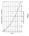
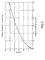
- the d-axis current command Idref is output, having been determined from the input torque command Tref in accordance with the coefficient graph of Fig. 4.
- the q-axis current command Iqref is output, having been determined from the input torque command Tref in accordance with the functional characteristic of Fig. 4.
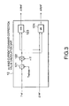
- the action of the dq axes current command correction value calculation unit 12 will be described with reference to Fig. 3.
- the dq axes current command correction value calculation unit 12 has a divider 121, a multiplier 122, a cosine calculator 123 and a sine calculator 124. As a whole it inputs the current command correction value ⁇ Iref output from the terminal voltage uniformity control unit 20, determining and outputting the d-axis current command correction value ⁇ Idref and q-axis current command correction value ⁇ Iqref in accordance with the following calculation.
- the multiplier 122 multiplies the ratio Trate by ⁇ /2 and outputs Trate ⁇ ⁇ /2.
- the cosine calculator 123 and sine calculator 124 perform the following calculation to determine the d-axis current command correction value ⁇ Idref and q-axis current command correction value ⁇ Iqref as follows.
- ⁇ I dref ⁇ I ref • cos(T rate • ⁇ / 2)
- I qref ⁇ I ref • sin(T rate • ⁇ / 2)
- the dq axes current command correction unit 13 inputs the d-axis current command Idref and q-axis current command Iqref output from the dq axes current command setting unit 11, together with the d-axis current command correction value ⁇ Idref and q-axis current command correction value ⁇ Iqref output from the dq axes current command correction value calculation unit 12, determining and outputting a new d-axis current command Idref and q-axis current command Iqref corrected according to the following calculations.
- I dref I dref+ ⁇ I dref
- I qref I qref+ ⁇ I qref
- s is a Laplace operator
- Kp is the relative gain
- Ki is the integral gain.
- the voltage vector length restriction unit 19 inputs the voltage vector length V1 output from the voltage vector length calculation unit 18, and the inverter input direct-current voltage Vdc, determining the restricted voltage vector restriction length Vllim.
- This Formula (12) represents fundamental wave voltage amplitude in one-pulse waveform voltage mode, which is to say a mode wherein one-pulse waveform voltage is output so as to turn the inverter switching element on and off once for each output frequency cycle.
- the coefficient 0.9 in the formula is the one required to set this at a value 10% lower in order to give control margin.
- This motor control device has a dq axes current command setting unit 11, a field-weakening axis angle setting unit 22, an ft coordinates transformation unit 23, an f-axis current command correction unit 24, an ft inverse coordinates transformation unit 25, a d-axis current control unit 16, a q-axis current control unit 17, a voltage vector length calculation unit 18, a voltage vector length restriction unit 19, a terminal voltage uniformity control unit 20, and a dq three-phase transformation unit 21.
- Those component elements which are the same as or correspond to component elements of the control device illustrated in Fig. 2 have been allocated the same codes, and will not be described separately.
- the field-weakening axis angle setting unit 22 inputs the torque command Tref, outputting the maximum field-weakening angle value or an approximation thereto as the field-weakening angle establishment value Qft.
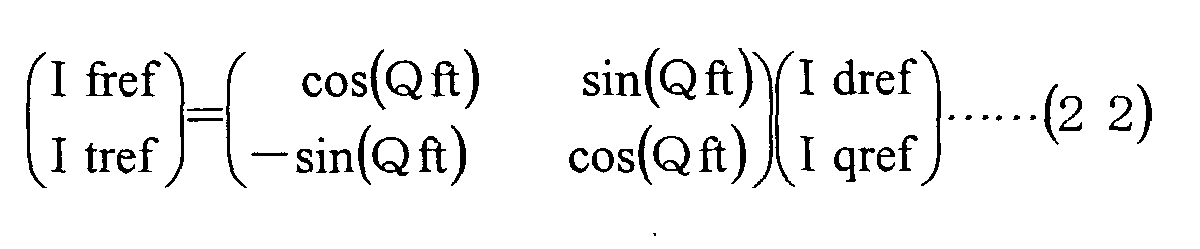
- the ft coordinates transformation unit 23 determines the f-axis current command Ifref and t-axis current command Itref as
- the ft inverse coordinates transformation unit 25 inputs the f-axis current command Ifref output from the f-axis current command correction unit 24, the t-axis current command Itref output from the ft coordinates transformation unit 23, and the field-weakening angle establishment value Qft output from the field-weakening axis angle setting unit 22, determining a new d-axis current command Idref and q-axis current command Iqref as
- Fig. 8 illustrates the terminal voltage uniformity curve in a motor and dq-axis coordinates where the magnetic flux of the permanent magnet ⁇ pm, d-axis inductance Ld and q-axis inductance Lq are respectively 0.0573[Wb], 1.81[mH] and 4.46[mH].
- the field-weakening angle establishment value Qft is set in a direction centripetal to the equivalent terminal voltage curve (direction of the arrow in the drawing) at the dq axes current command point output from the dq axes current command setting unit 11.
- a fourth embodiment With reference to Fig. 9.
- This embodiment closely resembles the control device illustrated in Fig. 6, and the majority of the component elements are common to both. The only difference is the content of the ft coordinates transformation unit 23, the remainder being the same.
- the ft coordinates transformation unit 23 inputs the dq axes current commands Idref, Iqref output from the dq axes current command setting unit 11 along with the field-weakening angle establishment value Qft output from the field-weakening axis angle setting unit 22, determining and outputting the f-axis current command Ifref and t-axis current command Itref.
- the abovementioned coordinate transformation shows that the point of origin of the ft coordinates axis shifts -Idz in the direction of the d-axis, while the phase angle rotates by the angle Qft. If field-weakening control is implemented as far as the point of origin of the ft coordinates axis, the result is that the motor terminal voltage becomes zero and comes to be in the direction where field weakening works most reliably.
- the ft inverse coordinates transformation unit 25 inputs the f-axis current command Ifref output from the f-axis current command correction unit 24, the t-axis current command Itref output from the f-axis current command correction unit 27, and the field-weakening angle setting value Qft output from the field-weakening axis angle setting unit 22, determining the new d-axis current command Idref and q-axis current command Iqref by means of the following calculation.
- a t-axis current command correction unit 27 which serves to calculate the t-axis current command correction value ⁇ Itref in order to correct the t-axis current command Itref. All other component elements are the same as those of Fig. 9.
- This f-axis current command correction unit 27 inputs the torque command Tref, the motor rotation angle speed ⁇ r, the d-axis voltage Vd output from the d-axis current control unit 16, the q-axis voltage Vq output from the q-axis current control unit 17, and the dq axes current commands Idref, Iqref output from the ft inverse coordinates transformation unit 25, determining the t-axis current command correction value ⁇ Itref.
- the t-axis current command correction value ⁇ Itref obtained in this manner is added in the adder 28 to the t-axis current command Itref output by the ft coordinates transformation unit 23 to yield the new t-axis current command Itref, which is fed to the ft inverse coordinates transformation unit 25.
- the control device of this embodiment has a dq axes current command setting unit 11, a field-weakening axis angle setting unit 22, an ft coordinates transformation unit 29, an actual current ft coordinates transformation unit 30, a t-axis current control unit 31, and a one-pulse waveform voltage calculation unit 32.
- the functions of the dq axes current command setting unit 11 and the field-weakening axis angle setting unit 22 are the same as those of the respective component elements of the control device illustrated in Fig. 6 and already described.
- s is a differential operator
- G(s) is the control gain in proportional/integral control and elsewhere.
- the one-pulse waveform voltage calculation unit 32 inputs the voltage phase angle ⁇ V of Formula (35) output from the t-axis current control unit 31, the motor rotor potential ⁇ r, and the inverter input direct-current voltage Vdc, determining the three-phase one-pulse waveform voltages Vu, Vv and Vw.
- Vvo cos ( ⁇ r + ⁇ V - 2 ⁇ /3 )
- Vwo cos ( ⁇ r + ⁇ V - 4 ⁇ /3 )
- the three-phase one-pulse waveform voltages Vu, Vv and Vw are determined from the results of the calculations in accordance with the following condition portions.
- the present invention makes it possible for stable and effective field-weakening control to be implemented in a motor control device which implements field-weakening control whatever torque is output.
Landscapes
- Engineering & Computer Science (AREA)
- Power Engineering (AREA)
- Control Of Ac Motors In General (AREA)
- Control Of Electric Motors In General (AREA)
- Control Of Motors That Do Not Use Commutators (AREA)
Abstract
Description




Claims (7)
- A motor control device for controlling a permanent magnet reluctance motor which generates torque corresponding to a combined value of a torque resulting from a permanent magnet and a reluctance torque, comprising:correction means for correcting a current command value so as to prevent a motor terminal voltage from exceeding a maximum inverter output voltage; andvariation means in response to a magnitude of a given torque command for varying an angle of a motor to an current command value output from said correction means.
- A motor control device for controlling a permanent magnet reluctance motor which generates torque corresponding to a combined value of a torque resulting from a permanent magnet and a reluctance torque, comprising:a dq axes current command setting unit which calculates both a d-axis current command corresponding to an axial direction of a permanent magnet and a q-axis current command in a direction at right angles thereto on the basis of a given torque command in accordance with previously supplied patterns;a d-axis current control unit which calculates a d-axis voltage in order to permit a d-axis current feedback value to track said d-axis current command;a q-axis current control unit which calculates a q-axis voltage in order to permit a q-axis current feedback value to track said q-axis current command;a voltage vector length calculation unit which determines a voltage vector whereof a d-axis voltage and q-axis voltage are components;a voltage vector length restriction unit which compares said voltage vector length and an inverter direct-current input voltage, and calculates a voltage vector length restriction value which is restricted in such a manner that said voltage vector length does not exceed a maximum inverter output voltage as determined in accordance with said inverter direct-current input voltage;a terminal voltage uniformity control unit which calculates said voltage command correction value required in order to ensure that said voltage vector length tallies with said voltage vector length restriction value;a dq axes current command correction value calculation unit which calculates said d-axis current command correction value and q-axis current command correction value in accordance with said torque command;a dq axes current command correction unit which corrects said d-axis current command by said d-axis current command correction value, and said q-axis current command by said q-axis current command correction value; anda dq three-phase transformation unit which transforms said d-axis voltage command and q-axis voltage command into a three-phase command on the basis of said d-axis voltage output from said d-axis current control unit, said q-axis voltage output from said q-axis current control unit, and a motor rotor position detection angle.
- A motor control device for controlling a permanent magnet reluctance motor which generates torque corresponding to a combined value of a torque resulting from a permanent magnet and a reluctance torque, comprising:a dq axes current command setting unit which calculates both a d-axis current command corresponding to an axial direction of a permanent magnet and a q-axis current command in a direction at right angles thereto on the basis of a given torque command in accordance with previously supplied patterns;a field-weakening axis angle setting unit which calculates a field-weakening axis angle on the basis of said torque command;an ft coordinates transformation unit which transforms said d-axis current command and q-axis current command into an f-axis current command corresponding to a direction of said field-weakening axis angle and a t-axis current command in a direction at right angles thereto;an f-axis current command correction unit which corrects said f-axis current command by a current command correction value;an ft inverse coordinates transformation unit which transforms said f-axis current command and said t-axis current command corrected by said f-axis current command correction unit into new d-axis and q-axis current commands;a d-axis current control unit which calculates a q-axis voltage in order to permit a d-axis current feedback value to track said d-axis current command obtained through said ft inverse coordinates transformation unit;a q-axis current control unit which calculates a q-axis voltage in order to permit a q-axis current feedback value to track said q-axis current command obtained through said ft inverse coordinates transformation unit;a voltage vector length calculation unit which determines a voltage vector whereof a d-axis voltage and q-axis voltage are components;a voltage vector length restriction unit which compares a voltage vector length and inverter direct-current input voltage, and calculates a voltage vector length restriction value which is restricted in such a manner that said voltage vector length does not exceed a maximum inverter output voltage as determined in accordance with an inverter direct-current input voltage;a terminal voltage uniformity control unit which calculates a voltage command correction value required in order to ensure that said voltage vector length tallies with said voltage vector length restriction value; anda dq three-phase transformation unit which transforms a d-axis voltage command and q-axis voltage command into a three-phase command on the basis of said d-axis voltage output from a d-axis current control unit, said q-axis voltage output from said q-axis current control unit, and a motor rotor position detection angle.
- The motor control device according to Claim 3,
wherein said field-weakening axis angle setting unit calculates said field-weakening axis angle on the basis of said d-axis and q-axis current commands deduced from said torque command. - The motor control device according to Claim 3,
wherein said ft coordinates transformation unit transforms a ft coordinates by determining an origin of a ft coordinates axis as a point on a dq coordinates axis at which a short-circuit current flows when a motor is rotated with terminals thereof short-circuited. - The motor control device according to Claim 3, further comprising:
a t-axis current command correction unit which based on said torque command, a motor rotation angle speed, and said d-axis and q-axis current commands and voltage commands output from said ft inverse coordinates transformation unit calculates a t-axis current command correction value required in order to correct derivations in a motor output torque relative to said torque command caused by correction of said f-axis current command as a result of terminal voltage uniformity control. - A motor control device for controlling a permanent magnet reluctance motor which generates torque corresponding to a combined value of a torque resulting from a permanent magnet and a reluctance torque, comprising:a dq axes current command setting unit which calculates both a d-axis current command corresponding to an axial direction of a permanent magnet and a q-axis current command in a direction at right angles thereto on the basis of a given torque command;a field-weakening axis angle setting unit which calculates a field-weakening axis angle on the basis of said torque command;an ft coordinates transformation unit into which a d-axis current command and q-axis current command are input to obtain a t-axis current command in a direction at right angles to a direction of a field-weakening axis angle;an actual current ft coordinates transformation unit which calculates a t-axis current on the basis of d-axis and q-axis current feedback values and said field-weakening axis angle;a t-axis current control unit which calculates a voltage potential angle on the basis of a deviation between said t-axis current command and said t-axis current; anda one-pulse waveform voltage calculation unit which uses said voltage phase angle, inverter input direct-current voltage and a motor rotor phase to calculate a one-pulse waveform three-phase voltage command required in order to turn inverter switch elements on and off once for each output frequency cycle.
Priority Applications (1)
| Application Number | Priority Date | Filing Date | Title |
|---|---|---|---|
| EP07111675A EP1835614B1 (en) | 2000-01-07 | 2001-01-05 | Motor control device |
Applications Claiming Priority (2)
| Application Number | Priority Date | Filing Date | Title |
|---|---|---|---|
| JP2000001652 | 2000-01-07 | ||
| JP2000001652A JP3566163B2 (en) | 2000-01-07 | 2000-01-07 | Motor control device |
Related Child Applications (1)
| Application Number | Title | Priority Date | Filing Date |
|---|---|---|---|
| EP07111675A Division EP1835614B1 (en) | 2000-01-07 | 2001-01-05 | Motor control device |
Publications (3)
| Publication Number | Publication Date |
|---|---|
| EP1115196A2 true EP1115196A2 (en) | 2001-07-11 |
| EP1115196A3 EP1115196A3 (en) | 2006-04-26 |
| EP1115196B1 EP1115196B1 (en) | 2008-10-29 |
Family
ID=18530855
Family Applications (2)
| Application Number | Title | Priority Date | Filing Date |
|---|---|---|---|
| EP07111675A Expired - Lifetime EP1835614B1 (en) | 2000-01-07 | 2001-01-05 | Motor control device |
| EP01100380A Expired - Lifetime EP1115196B1 (en) | 2000-01-07 | 2001-01-05 | Motor control device |
Family Applications Before (1)
| Application Number | Title | Priority Date | Filing Date |
|---|---|---|---|
| EP07111675A Expired - Lifetime EP1835614B1 (en) | 2000-01-07 | 2001-01-05 | Motor control device |
Country Status (4)
| Country | Link |
|---|---|
| US (1) | US6429620B2 (en) |
| EP (2) | EP1835614B1 (en) |
| JP (1) | JP3566163B2 (en) |
| DE (2) | DE60144166D1 (en) |
Cited By (7)
| Publication number | Priority date | Publication date | Assignee | Title |
|---|---|---|---|---|
| WO2004027976A1 (en) * | 2002-09-20 | 2004-04-01 | Honeywell International Inc. | Improved torque generation for salient-pole synchronous machine for start-up of a prime mover |
| US6940251B1 (en) | 2004-04-30 | 2005-09-06 | Honeywell International Inc. | Decoupling of cross coupling for floating reference frame controllers for sensorless control of synchronous machines |
| EP2093098A1 (en) * | 2008-02-21 | 2009-08-26 | Yamaha Hatsudoki Kabushiki Kaisha | Wheel driving apparatus and electric vehicle including the same |
| EP2779429A3 (en) * | 2013-03-11 | 2015-04-08 | Steering Solutions IP Holding Corporation | Method of current reference generation for a motor |
| US9461574B2 (en) | 2013-03-12 | 2016-10-04 | Steering Solutions Ip Holding Corporation | Motor control system for determining a reference d-axis current and a q-axis current |
| US9531311B2 (en) | 2013-03-13 | 2016-12-27 | Steering Solutions Ip Holding Corporation | Generation of a current reference to control a brushless motor |
| US10526008B1 (en) | 2018-07-31 | 2020-01-07 | Steering Solutions Ip Holding Corporation | Machine current limiting for permanent magnet synchronous machines |
Families Citing this family (39)
| Publication number | Priority date | Publication date | Assignee | Title |
|---|---|---|---|---|
| JP3692046B2 (en) | 2001-03-16 | 2005-09-07 | 株式会社東芝 | Motor control device |
| US6741060B2 (en) * | 2001-04-05 | 2004-05-25 | Delphi Technologies, Inc. | Method and system for controlling a permanent magnet machine during fault conditions |
| JP3692085B2 (en) * | 2002-02-21 | 2005-09-07 | 株式会社東芝 | Motor control method and apparatus |
| JP4008724B2 (en) * | 2002-03-12 | 2007-11-14 | 株式会社東芝 | Motor control device |
| JP2004015892A (en) * | 2002-06-05 | 2004-01-15 | Toshiba Corp | Inverter control device and electric vehicle |
| US6876169B2 (en) * | 2003-01-14 | 2005-04-05 | Delphi Technologies, Inc. | Method and controller for field weakening operation of AC machines |
| US7262536B2 (en) * | 2003-08-11 | 2007-08-28 | General Motors Corporation | Gearless wheel motor drive system |
| US7065437B2 (en) * | 2003-08-21 | 2006-06-20 | Delphi Technologies, Inc. | Current limit for an electric machine |
| US6982533B2 (en) * | 2003-09-17 | 2006-01-03 | Rockwell Automation Technologies, Inc. | Method and apparatus to regulate loads |
| JP2005219133A (en) * | 2004-02-03 | 2005-08-18 | Fanuc Ltd | Servo motor control device for robot, and robot |
| EP1722469A1 (en) * | 2004-02-23 | 2006-11-15 | NSK Ltd., | Motor-driven power steering device control device |
| JP4737087B2 (en) * | 2004-03-26 | 2011-07-27 | 三菱電機株式会社 | Control device for permanent magnet synchronous motor |
| US7095209B2 (en) * | 2004-09-29 | 2006-08-22 | Rockwell Automation Technologies, Inc. | Method and apparatus to regulate torque provided to loads |
| US7667426B2 (en) * | 2005-06-17 | 2010-02-23 | Gm Global Technology Operations, Inc. | On-line minimum copper loss control of interior permanent-magnet synchronous machine for automotive applications |
| JP4972135B2 (en) * | 2005-08-26 | 2012-07-11 | 三洋電機株式会社 | Motor control device |
| JP4655871B2 (en) * | 2005-10-19 | 2011-03-23 | 株式会社日立製作所 | Field weakening vector control device and module for permanent magnet synchronous motor |
| EP1777806A2 (en) * | 2005-10-21 | 2007-04-25 | NSK Ltd. | Motor drive control apparatus and electric power steering apparatus |
| JP2009519878A (en) * | 2005-12-20 | 2009-05-21 | オーチス エレベータ カンパニー | Elevator drive device control method |
| JP4754417B2 (en) * | 2006-06-26 | 2011-08-24 | 本田技研工業株式会社 | Control device for permanent magnet type rotating electrical machine |
| JP4895703B2 (en) * | 2006-06-28 | 2012-03-14 | 三洋電機株式会社 | Motor control device |
| US7543679B2 (en) | 2006-07-28 | 2009-06-09 | Delphi Technologies, Inc. | Compensation of periodic sensor errors in electric power steering systems |
| US7549504B2 (en) | 2006-07-28 | 2009-06-23 | Delphi Technologies, Inc. | Quadrant dependent active damping for electric power steering |
| US7725227B2 (en) | 2006-12-15 | 2010-05-25 | Gm Global Technology Operations, Inc. | Method, system, and apparatus for providing enhanced steering pull compensation |
| JP5168448B2 (en) * | 2007-02-26 | 2013-03-21 | 株式会社ジェイテクト | Motor control device and electric power steering device |
| KR101340527B1 (en) * | 2007-05-30 | 2013-12-11 | 엘지전자 주식회사 | Motor Driver System and Controlling Method for the Same |
| JP4969344B2 (en) * | 2007-07-06 | 2012-07-04 | 三菱電機株式会社 | Electric vehicle power converter |
| KR101561922B1 (en) * | 2007-12-21 | 2015-10-20 | 엘지전자 주식회사 | Motor control method of air conditioner |
| JP5243869B2 (en) * | 2008-07-14 | 2013-07-24 | 株式会社安川電機 | AC motor winding switching device and inverter device |
| US20100066289A1 (en) * | 2008-09-17 | 2010-03-18 | Ford Global Technologies, Llc | System and method for controlling an electric motor |
| JP5390970B2 (en) * | 2009-07-15 | 2014-01-15 | カヤバ工業株式会社 | Motor control device |
| JP5550672B2 (en) * | 2012-03-30 | 2014-07-16 | 株式会社東芝 | Motor control device |
| KR101846872B1 (en) | 2015-06-16 | 2018-05-24 | 현대자동차 주식회사 | Apparatus and method for aontrolling motor of eco-friendly vehicle |
| JP6403904B2 (en) * | 2015-11-25 | 2018-10-10 | 三菱電機株式会社 | Control device for permanent magnet type rotating electrical machine |
| JP6855708B2 (en) * | 2016-08-25 | 2021-04-07 | 株式会社アドヴィックス | Vehicle braking control device |
| CN106712631B (en) * | 2016-12-26 | 2019-09-27 | 广东美的制冷设备有限公司 | Permanent magnet synchronous motor system and its method and a device for controlling weak magnetism |
| EP3883126A4 (en) * | 2018-11-15 | 2022-01-19 | Nissan Motor Co., Ltd. | ELECTRIC VEHICLE CONTROL METHOD AND CONTROL DEVICE |
| JP7192649B2 (en) * | 2019-05-09 | 2022-12-20 | 株式会社デンソー | Rotating electric machine controller |
| JP7342592B2 (en) * | 2019-10-08 | 2023-09-12 | 日本精工株式会社 | Motor control device, motor control method, and electric power steering device |
| EP4346087A1 (en) * | 2022-09-29 | 2024-04-03 | Schneider Toshiba Inverter Europe SAS | Determinations of static load torque at standstill |
Family Cites Families (6)
| Publication number | Priority date | Publication date | Assignee | Title |
|---|---|---|---|---|
| US3769564A (en) * | 1972-08-30 | 1973-10-30 | Allis Louis Co | Method and means for limiting the maximum horsepower output of a self-excited alternating current motor |
| US4649331A (en) * | 1985-05-13 | 1987-03-10 | General Electric Company | Flux-weakening regime operation of an interior permanent magnet synchronous motor |
| US4740738A (en) * | 1986-09-17 | 1988-04-26 | Westinghouse Electric Corp. | Reluctance motor control system and method |
| DE4314211C2 (en) * | 1993-04-30 | 2000-06-21 | Daimler Chrysler Ag | Method for controlling the shutdown process in the strands of a reluctance motor |
| US5900712A (en) * | 1998-02-20 | 1999-05-04 | General Motors Corporation | Transistor drive circuit and control for a switched reluctance motor |
| JP3577218B2 (en) * | 1998-06-10 | 2004-10-13 | オークマ株式会社 | Control device for reluctance type synchronous motor |
-
2000
- 2000-01-07 JP JP2000001652A patent/JP3566163B2/en not_active Expired - Lifetime
-
2001
- 2001-01-02 US US09/751,387 patent/US6429620B2/en not_active Expired - Lifetime
- 2001-01-05 EP EP07111675A patent/EP1835614B1/en not_active Expired - Lifetime
- 2001-01-05 DE DE60144166T patent/DE60144166D1/en not_active Expired - Lifetime
- 2001-01-05 DE DE60136307T patent/DE60136307D1/en not_active Expired - Lifetime
- 2001-01-05 EP EP01100380A patent/EP1115196B1/en not_active Expired - Lifetime
Cited By (10)
| Publication number | Priority date | Publication date | Assignee | Title |
|---|---|---|---|---|
| WO2004027976A1 (en) * | 2002-09-20 | 2004-04-01 | Honeywell International Inc. | Improved torque generation for salient-pole synchronous machine for start-up of a prime mover |
| US6791204B2 (en) | 2002-09-20 | 2004-09-14 | Honeywell International Inc. | Torque generation for salient-pole synchronous machine for start-up of a prime mover |
| US6940251B1 (en) | 2004-04-30 | 2005-09-06 | Honeywell International Inc. | Decoupling of cross coupling for floating reference frame controllers for sensorless control of synchronous machines |
| EP2093098A1 (en) * | 2008-02-21 | 2009-08-26 | Yamaha Hatsudoki Kabushiki Kaisha | Wheel driving apparatus and electric vehicle including the same |
| US8004223B2 (en) | 2008-02-21 | 2011-08-23 | Yamaha Hatsudoki Kabushiki Kaisha | Wheel driving apparatus and electric vehicle including the same |
| EP2779429A3 (en) * | 2013-03-11 | 2015-04-08 | Steering Solutions IP Holding Corporation | Method of current reference generation for a motor |
| US9369078B2 (en) | 2013-03-11 | 2016-06-14 | Steering Solutions Ip Holding Corporation | Method of current reference generation for a motor |
| US9461574B2 (en) | 2013-03-12 | 2016-10-04 | Steering Solutions Ip Holding Corporation | Motor control system for determining a reference d-axis current and a q-axis current |
| US9531311B2 (en) | 2013-03-13 | 2016-12-27 | Steering Solutions Ip Holding Corporation | Generation of a current reference to control a brushless motor |
| US10526008B1 (en) | 2018-07-31 | 2020-01-07 | Steering Solutions Ip Holding Corporation | Machine current limiting for permanent magnet synchronous machines |
Also Published As
| Publication number | Publication date |
|---|---|
| US6429620B2 (en) | 2002-08-06 |
| DE60136307D1 (en) | 2008-12-11 |
| EP1835614A1 (en) | 2007-09-19 |
| JP2001197800A (en) | 2001-07-19 |
| EP1835614B1 (en) | 2011-03-02 |
| US20010019251A1 (en) | 2001-09-06 |
| EP1115196B1 (en) | 2008-10-29 |
| JP3566163B2 (en) | 2004-09-15 |
| DE60144166D1 (en) | 2011-04-14 |
| EP1115196A3 (en) | 2006-04-26 |
Similar Documents
| Publication | Publication Date | Title |
|---|---|---|
| US6429620B2 (en) | Motor control device | |
| US6362586B1 (en) | Method and device for optimal torque control of a permanent magnet synchronous motor over an extended speed range | |
| US7554281B2 (en) | Synchronous machine control apparatus | |
| US8519648B2 (en) | Temperature compensation for improved field weakening accuracy | |
| US20040135533A1 (en) | Speed control device for ac electric motor | |
| EP3252941B1 (en) | Inverter control apparatus and motor driving system | |
| EP1221762A2 (en) | Method and system for controlling a synchronous machine over full operating range | |
| JP4754417B2 (en) | Control device for permanent magnet type rotating electrical machine | |
| US10469014B2 (en) | Control device for permanent magnet-type rotating electrical machine | |
| US6359415B1 (en) | Apparatus for controlling synchronous motor | |
| US6707266B2 (en) | Motor control device | |
| JP2001161099A (en) | Control scheme for synchronous motor | |
| US7145311B2 (en) | Vector control device of winding field type synchronous machine | |
| JP4056237B2 (en) | Control device for synchronous machine | |
| JP4402600B2 (en) | Synchronous motor drive system and synchronous motor drive method | |
| JP7194320B2 (en) | motor controller | |
| CN113819623B (en) | Method and device for controlling operation of motor, air conditioner and storage medium | |
| JP2002233198A (en) | Motor drive circuit | |
| Niu et al. | Simultaneous MTPA and sensorless control strategy for IPMSM drives based on high-frequency signal injection | |
| JP2000197398A (en) | Control device for synchronous motor | |
| Fujii et al. | Influence of parameter variations on operating characteristics of MTPF control for DTC-based PMSM drive system | |
| JP2003264999A (en) | AC motor vector control device | |
| US20140306629A1 (en) | Motor drive control system | |
| JP2000341983A (en) | Control device for embedded magnet type synchronous motor | |
| Zaky et al. | Decoupled speed and torque control of IPMSM drives using a novel load torque estimator. |
Legal Events
| Date | Code | Title | Description |
|---|---|---|---|
| PUAI | Public reference made under article 153(3) epc to a published international application that has entered the european phase |
Free format text: ORIGINAL CODE: 0009012 |
|
| AK | Designated contracting states |
Kind code of ref document: A2 Designated state(s): AT BE CH CY DE DK ES FI FR GB GR IE IT LI LU MC NL PT SE TR |
|
| AX | Request for extension of the european patent |
Free format text: AL;LT;LV;MK;RO;SI |
|
| PUAL | Search report despatched |
Free format text: ORIGINAL CODE: 0009013 |
|
| AK | Designated contracting states |
Kind code of ref document: A3 Designated state(s): AT BE CH CY DE DK ES FI FR GB GR IE IT LI LU MC NL PT SE TR |
|
| AX | Request for extension of the european patent |
Extension state: AL LT LV MK RO SI |
|
| 17P | Request for examination filed |
Effective date: 20061018 |
|
| AKX | Designation fees paid |
Designated state(s): DE FR |
|
| 17Q | First examination report despatched |
Effective date: 20070312 |
|
| GRAP | Despatch of communication of intention to grant a patent |
Free format text: ORIGINAL CODE: EPIDOSNIGR1 |
|
| GRAS | Grant fee paid |
Free format text: ORIGINAL CODE: EPIDOSNIGR3 |
|
| GRAA | (expected) grant |
Free format text: ORIGINAL CODE: 0009210 |
|
| AK | Designated contracting states |
Kind code of ref document: B1 Designated state(s): DE FR |
|
| REF | Corresponds to: |
Ref document number: 60136307 Country of ref document: DE Date of ref document: 20081211 Kind code of ref document: P |
|
| PLBE | No opposition filed within time limit |
Free format text: ORIGINAL CODE: 0009261 |
|
| STAA | Information on the status of an ep patent application or granted ep patent |
Free format text: STATUS: NO OPPOSITION FILED WITHIN TIME LIMIT |
|
| 26N | No opposition filed |
Effective date: 20090730 |
|
| PGFP | Annual fee paid to national office [announced via postgrant information from national office to epo] |
Ref country code: FR Payment date: 20100208 Year of fee payment: 10 |
|
| PGFP | Annual fee paid to national office [announced via postgrant information from national office to epo] |
Ref country code: DE Payment date: 20091231 Year of fee payment: 10 |
|
| REG | Reference to a national code |
Ref country code: FR Ref legal event code: ST Effective date: 20110930 |
|
| PG25 | Lapsed in a contracting state [announced via postgrant information from national office to epo] |
Ref country code: FR Free format text: LAPSE BECAUSE OF NON-PAYMENT OF DUE FEES Effective date: 20110131 |
|
| REG | Reference to a national code |
Ref country code: DE Ref legal event code: R119 Ref document number: 60136307 Country of ref document: DE Effective date: 20110802 |
|
| PG25 | Lapsed in a contracting state [announced via postgrant information from national office to epo] |
Ref country code: DE Free format text: LAPSE BECAUSE OF NON-PAYMENT OF DUE FEES Effective date: 20110802 |