EP1114963A2 - Dekorationsgegenstand mit faltbaren Elementen - Google Patents
Dekorationsgegenstand mit faltbaren Elementen Download PDFInfo
- Publication number
- EP1114963A2 EP1114963A2 EP00311535A EP00311535A EP1114963A2 EP 1114963 A2 EP1114963 A2 EP 1114963A2 EP 00311535 A EP00311535 A EP 00311535A EP 00311535 A EP00311535 A EP 00311535A EP 1114963 A2 EP1114963 A2 EP 1114963A2
- Authority
- EP
- European Patent Office
- Prior art keywords
- members
- article
- display position
- decorative
- decorative article
- Prior art date
- Legal status (The legal status is an assumption and is not a legal conclusion. Google has not performed a legal analysis and makes no representation as to the accuracy of the status listed.)
- Withdrawn
Links
- 241000533950 Leucojum Species 0.000 claims description 7
- 230000013011 mating Effects 0.000 claims description 2
- 238000012986 modification Methods 0.000 description 2
- 230000004048 modification Effects 0.000 description 2
- 241000239290 Araneae Species 0.000 description 1
Images


Classifications
-
- F—MECHANICAL ENGINEERING; LIGHTING; HEATING; WEAPONS; BLASTING
- F21—LIGHTING
- F21V—FUNCTIONAL FEATURES OR DETAILS OF LIGHTING DEVICES OR SYSTEMS THEREOF; STRUCTURAL COMBINATIONS OF LIGHTING DEVICES WITH OTHER ARTICLES, NOT OTHERWISE PROVIDED FOR
- F21V17/00—Fastening of component parts of lighting devices, e.g. shades, globes, refractors, reflectors, filters, screens, grids or protective cages
- F21V17/007—Fastening of component parts of lighting devices, e.g. shades, globes, refractors, reflectors, filters, screens, grids or protective cages with provision for shipment or storage
-
- B—PERFORMING OPERATIONS; TRANSPORTING
- B44—DECORATIVE ARTS
- B44C—PRODUCING DECORATIVE EFFECTS; MOSAICS; TARSIA WORK; PAPERHANGING
- B44C3/00—Processes, not specifically provided for elsewhere, for producing ornamental structures
- B44C3/12—Uniting ornamental elements to structures, e.g. mosaic plates
-
- B—PERFORMING OPERATIONS; TRANSPORTING
- B44—DECORATIVE ARTS
- B44C—PRODUCING DECORATIVE EFFECTS; MOSAICS; TARSIA WORK; PAPERHANGING
- B44C5/00—Processes for producing special ornamental bodies
-
- F—MECHANICAL ENGINEERING; LIGHTING; HEATING; WEAPONS; BLASTING
- F21—LIGHTING
- F21S—NON-PORTABLE LIGHTING DEVICES; SYSTEMS THEREOF; VEHICLE LIGHTING DEVICES SPECIALLY ADAPTED FOR VEHICLE EXTERIORS
- F21S4/00—Lighting devices or systems using a string or strip of light sources
- F21S4/20—Lighting devices or systems using a string or strip of light sources with light sources held by or within elongate supports
-
- Y—GENERAL TAGGING OF NEW TECHNOLOGICAL DEVELOPMENTS; GENERAL TAGGING OF CROSS-SECTIONAL TECHNOLOGIES SPANNING OVER SEVERAL SECTIONS OF THE IPC; TECHNICAL SUBJECTS COVERED BY FORMER USPC CROSS-REFERENCE ART COLLECTIONS [XRACs] AND DIGESTS
- Y10—TECHNICAL SUBJECTS COVERED BY FORMER USPC
- Y10S—TECHNICAL SUBJECTS COVERED BY FORMER USPC CROSS-REFERENCE ART COLLECTIONS [XRACs] AND DIGESTS
- Y10S362/00—Illumination
- Y10S362/806—Ornamental or decorative
- Y10S362/807—Star
Definitions
- the present invention relates to decorative articles, and more particularly to a decorative article having foldable members which are hinged together for movement between a folded storage position and an unfolded display position.
- Decorative articles are typically covered with lights for display.
- the use of lighted decorative articles is common, particularly during holiday seasons.
- Shapes are utilized for decorative articles, such as for example, star shapes and snowflakes.
- the article In order for such articles to be plainly visible, the article must be of a sufficient size to be easily seen from great distances. Storage of such decorative articles can be difficult and inefficient in that a space large enough must be provided to store the entire article. Large articles are more costly to ship, and require more display space at point of sale.
- a decorative article in accordance with the present invention, includes a plurality of members hingedly connected to one another and movable between a folded storage position and an unfolded display position.
- Each of the members includes a top surface, a bottom surface, and first and second sides.
- the height of the article is defined between the top and bottom surfaces.
- a hinge interconnects adjacent members between respective first and second sides.
- Ones of the top surfaces overlay each other and ones of the bottom surfaces overlay each other in the article folded storage position, such that in the article folded storage position, the article has a height equal to the sum of the heights of the members, and in the article unfolded display position, the article has a height equal to the height of one of the members and wherein the members are arranged in a circular pattern.
- the members of the decorative article may include a track.
- the members of the decorative article may include a triangular configuration.
- the members of the decorative article may include a snowflake configuration.
- the members of the decorative article advantageously includes a plurality of lights attached to said members.
- At least one hinge of the article includes a lock for retaining the adjacent members in the unfolded display position.
- the decorative article includes a lug associated with one of said plurality of members, the lug mating with a slot associated with an adjacent member when said decorative article is in the unfolded display position, to provide a releasable connection between the said two members.
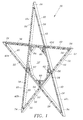
- FIGs. 1, 2, and 13 a first embodiment of the present decorative article is illustrated, and is generally identified by the numeral 30.
- Decorative article 30 is in the form of a star 32, having five projections or points 34.
- FIGs. 1 and 13 illustrates article 30 in an unfolded display position whereas FIG. 2 illustrates article 30 in a folded storage position within a container or box 36. Box 36 is utilized for shipping and storage of decorative article 30 when decorative article 30 is not in use.
- Article 30 includes a plurality of adjacent members 40 which are hingedly and foldably connected to one another to allow article 30 to move from the unfolded display position shown in FIG. 1 to the folded storage position shown in FIG. 2.
- Each member 40 is configured in the shape of a triangle which forms one of the points 34 of star 32.
- Article 30 is illustrated with five members 40, 40a-40e, it being understood that other configurations of article 30 are possible utilizing the present invention, and a star having five points 34 is shown for illustrative purposes only.
- Each member 40 includes a top surface 42, a bottom surface 44, a first side 46, and a second side 48.
- Members 40 may be fabricated from a track 50 having spaced apart walls 52 and 54. Track 50 may be utilized for mounting a string of lights between walls 52 and 54 as illustrated in FIGs. 14 and 15 using clips 56.
- Members 40 are hingedly interconnected utilizing hinges 60 which are attached to a first side 46 of one member 40 and a second side 48 of an adjoining member 40.
- Hinges 60 are disposed on alternating top and bottom surfaces 42 and 44 of adjacent members 40a-40e.
- a lock 62 Disposed on the opposite side of each hinge 60 is a lock 62 for rigidly locking adjacent members 40 together to form a rigid article 30 when in the unfolded display position.
- Members 40a and 40e are releasably interconnected utilizing a connector 64 extending from first side 46 of member 40a. Connector 64 mates with a portion of track 50 adjacent second side 48 of member 40e. Through use of connector 64 and locks 62, all members 40a-40e are rigidly connected in the unfolded display position as illustrated in FIG. 1.
- each member 40 is disposed in an overlying position with respect to an adjoining member 40 as illustrated in FIG. 2.
- the overall height of article 30 in the folded storage position is equal to the sum of the heights of each member 40, where the height of a member 40 is defined as the distance between the top 42 and bottom 44 surfaces of a member 40.
- member 40a is rotated in the direction of arrow 70.
- top surface 42 of member 40a lies adjacent to top surface 42 of member 40b.
- Second side 48 of member 40a is hingedly interconnected to first side 46 of member 40b utilizing a hinge 60 (FIG. 2).
- a lock 62 (FIG. 2) interconnects bottom surfaces 44 of members 40a and 40b.
- members 40a and 40b are rotated in the direction of arrow 72 thereby exposing the bottom surface 44 of member 40c.
- Bottom surfaces 44 of member 40b and 40c lie adjacent one another in the folded storage position of article 30 as illustrated in FIG. 2.
- Side wall 48 of member 40b is hingedly interconnected to side wall 46 of member 40c by a hinge 60 which is disposed on bottom surfaces 44 of members 40b and 40c.
- a lock 62 is disposed below hinge 60 on the top surfaces 42 of members 40b and 40c in order to lock members 40b and 40c together in the unfolded display position.
- members 40a, 40b, and 40c are rotated in the direction of arrow 74 thereby exposing the top surface 42 of member 40d.
- the top surfaces of members 40c and 40d lie adjacent one another in the folded storage position of article 30.
- Second side 48 of member 40c is hingedly interconnected to first side 46 of member 40d utilizing a hinge 60 (FIG. 2).
- a lock 62 is disposed on bottom surfaces 44 of members 40c and 40d.
- FIG. 6 illustrates decorative article 30 in the completely unfolded display position wherein members 40a, 40b, 40c, and 40d are rotated in the direction of arrow 76 to expose the bottom surface of member 40e. Bottom surfaces 44 of members 40d and 40e are disposed adjacent to one another in the folded storage position of article 30. Second side 48 of member 40d is hingedly interconnected to first side 46 of member 40e utilizing a hinge 60, which is disposed on the bottom surface 44 of members 40d and 40e. Member 40a is moved in the direction of arrow 78 to interconnect member 40a to member 40e utilizing connector 64.
- FIG. 7 illustrates article 30 with the top surface 42 in the upward position.
- the height of article 30 in the unfolded display position illustrated in FIGs. 1, 7, and 13 is the height of one member 40.
- members 40 are arranged in a circular configuration or pattern about the center of star 32 to form a substantial 360° figure.
- Opposite top and bottom surfaces 42 and 44 of adjoining members 40 are disposed adjacent to one another in the folded storage position illustrated in FIG. 2, such that members 40 unfold in a fan-like alternating manner from the folded storage position illustrated in FIG. 2 to the unfolded display position illustrated in FIGs. 1, 7, and 13.
- FIG. 8 illustrates a releasable connection formed between member 40a and member 40e through connector 64.
- Connector 64 mates with a slot 82 within track 50 of second side 48 of member 40e.
- FIG. 9 illustrates a hinge 60 between adjacent members 40 interconnecting a first side 46 to a second side 48 of a respective member 40.
- Hinge 60 includes a interconnected fingers 60a, 60b, 60c, and 60d which are interconnected by a pin 84.
- hinge 60 is interconnected to track 50 utilizing fasteners such as, for example, screws 86.
- Lock 62 is illustrated for interconnecting adjacent members 40 between respective side walls 46 and 48.
- Lock 62 is interconnected to track 50 utilizing fasteners such as, for example, screws 88.
- Lock 62 includes a catch 90 which engages a side wall 46 or 48 for rigidly connecting adjacent members 40 in the unfolded display position of article 30.
- article 30 may include a plurality of lights 100 disposed within track 50.
- Lights 100 may generally comprise a light string of a type known in the art which includes bulbs 102 and bases 104 connected by interconnecting wires 106.
- Base 104 is received within a clip 56 disposed within track 50 between walls 52 and 54.
- Decorative article 120 is in the form of a snowflake 122.
- Snowflake 122 includes six branches 124, wherein each branch includes a member 126.
- Adjacent members 126a-f are hingedly interconnected in a manner similar to members 40a-40e of decorative article 30, such that decorative article 120 has a folded storage position similar to that of decorative article 30 as illustrated in FIG. 2.
- FIG. 19 illustrates the use of a lock 62 for rigidly interconnecting adjacent members 126 of decorative article 120.
- FIG. 20 illustrates a hinge 60 for hingedly interconnecting adjacent members 126.
- FIG. 21 illustrates releasable connection formed by a connector 64 and slot 82 of adjoining members 126.
- Members 126 also include clips 56 for receiving a base 104 of lights 100.
- Decorative article 120 operates in a manner similar to decorative article 30 wherein members 126 unfold into a 360° configuration about the center of snowflake 122 and wherein opposite top and bottom surfaces lie adjacent to one another in the folded storage position.
- the present invention is not limited to a star or snowflake as illustrated. Additional embodiments such as, for example, a spider web pattern may also be utilized in which a plurality of hingedly joined members configurable in a 360° pattern in an unfolded display position can be utilized.
Landscapes
- Engineering & Computer Science (AREA)
- General Engineering & Computer Science (AREA)
- Display Racks (AREA)
- Credit Cards Or The Like (AREA)
- Purses, Travelling Bags, Baskets, Or Suitcases (AREA)
Applications Claiming Priority (4)
| Application Number | Priority Date | Filing Date | Title |
|---|---|---|---|
| US17189399P | 1999-12-23 | 1999-12-23 | |
| US171893P | 1999-12-23 | ||
| US722557 | 2000-11-28 | ||
| US09/722,557 US6488391B1 (en) | 1999-12-23 | 2000-11-28 | Decorative article having foldable members |
Publications (2)
| Publication Number | Publication Date |
|---|---|
| EP1114963A2 true EP1114963A2 (de) | 2001-07-11 |
| EP1114963A3 EP1114963A3 (de) | 2004-01-14 |
Family
ID=26867541
Family Applications (1)
| Application Number | Title | Priority Date | Filing Date |
|---|---|---|---|
| EP00311535A Withdrawn EP1114963A3 (de) | 1999-12-23 | 2000-12-21 | Dekorationsgegenstand mit faltbaren Elementen |
Country Status (2)
| Country | Link |
|---|---|
| US (1) | US6488391B1 (de) |
| EP (1) | EP1114963A3 (de) |
Families Citing this family (11)
| Publication number | Priority date | Publication date | Assignee | Title |
|---|---|---|---|---|
| WO2002063111A1 (en) * | 2001-02-07 | 2002-08-15 | Charles Hoberman | Loop assemblies having a central link |
| US6634767B2 (en) * | 2002-03-13 | 2003-10-21 | Shining Blick Enterprises Co., Ltd. | Sticking-positioned firework light |
| US8083376B2 (en) * | 2002-11-04 | 2011-12-27 | Tseng-Lu Chien | LED power failure light |
| US11082664B2 (en) * | 2004-07-06 | 2021-08-03 | Tseng-Lu Chien | Multiple functions LED night light |
| US20080198599A1 (en) * | 2007-02-20 | 2008-08-21 | Chi-Shih Lai | Combined glowing decorative structure |
| US9695996B2 (en) * | 2013-03-12 | 2017-07-04 | Inq-Energy, Inc. | Solar-powered roadway delineator |
| US10234104B2 (en) * | 2013-03-13 | 2019-03-19 | Nbcuniversal Media, Llc | Collapsible suspended lighting system |
| US11503937B2 (en) * | 2016-05-06 | 2022-11-22 | Linda SCHURR | Decorative articles |
| US10893646B2 (en) * | 2016-07-29 | 2021-01-19 | Brenda Marie Frew | Plant framing apparatus |
| USD953196S1 (en) | 2019-05-23 | 2022-05-31 | Ulta-Lit Tree Company | Clip |
| US10837627B1 (en) | 2019-06-21 | 2020-11-17 | Ulta-Lit Tree Company | Clip for holding a light bulb parallel to a light string |
Family Cites Families (14)
| Publication number | Priority date | Publication date | Assignee | Title |
|---|---|---|---|---|
| US1433273A (en) | 1921-03-09 | 1922-10-24 | Henry W Graves | Structural toy |
| US2853598A (en) | 1955-03-29 | 1958-09-23 | Jack E Dominik | Collapsible lamp with adjustable shade |
| US2894345A (en) | 1956-07-30 | 1959-07-14 | William L Bushnell | Decorative star |
| US3184366A (en) | 1962-04-03 | 1965-05-18 | Claude George | Collapsible display device |
| US3182186A (en) * | 1962-06-25 | 1965-05-04 | Raymond B Faulk | Polyhedral display devices |
| US3374798A (en) | 1964-12-07 | 1968-03-26 | Licentia Ekman & Brundin | Camouflage equipment |
| US3546049A (en) | 1967-05-25 | 1970-12-08 | Omniversal Design | Symmetrical non-cartesian multipleaxis joining of beams |
| US3704367A (en) | 1971-11-12 | 1972-11-28 | Lawrence J Korb | Lighted christmas star display |
| JPS548142B2 (de) | 1974-05-18 | 1979-04-12 | ||
| US4816316A (en) | 1987-02-11 | 1989-03-28 | Robbins Edward S Iii | Ribbed sheet |
| US5845451A (en) | 1996-01-31 | 1998-12-08 | Tolentino; Edgar Williams | Telescoping polygonal figure |
| US5629057A (en) | 1996-05-20 | 1997-05-13 | Toyo Electric Manufacturing Co. Ltd. | Collapsible lighted skeletal structure |
| US5876111A (en) * | 1996-09-04 | 1999-03-02 | Wu; Jeng-Shyong | Decorative lighting string with expandable, shrinkable and three-dimensional unit |
| US6273583B1 (en) | 1999-03-04 | 2001-08-14 | James Trisler | Folding star |
-
2000
- 2000-11-28 US US09/722,557 patent/US6488391B1/en not_active Expired - Fee Related
- 2000-12-21 EP EP00311535A patent/EP1114963A3/de not_active Withdrawn
Non-Patent Citations (1)
| Title |
|---|
| None |
Also Published As
| Publication number | Publication date |
|---|---|
| US6488391B1 (en) | 2002-12-03 |
| EP1114963A3 (de) | 2004-01-14 |
Similar Documents
| Publication | Publication Date | Title |
|---|---|---|
| EP1114963A2 (de) | Dekorationsgegenstand mit faltbaren Elementen | |
| US5205638A (en) | Lighted merchandise shelves | |
| US4417774A (en) | Collapsible display booth | |
| US5379540A (en) | Modular sign system | |
| US4979554A (en) | Flexible display panel | |
| AU2011209355B2 (en) | Item display stand | |
| US7726841B2 (en) | LED light device with changeable geometric system | |
| CN1054502C (zh) | 柜的安装方法及用于该方法的铰接装置 | |
| US7841676B2 (en) | Modular merchandising display system | |
| JPH0227041A (ja) | オフィス空間仕切り構造物 | |
| US20080172918A1 (en) | Convertible cube particularly usable for display of pictures, objects, images, messages, and illumination patterns | |
| US7066636B2 (en) | Ornamental lamp strings assembly | |
| US5628413A (en) | Modular display stand | |
| HK1037022A (en) | Decorative article having foldable members | |
| Gutman | American diner then and now | |
| CA2327964A1 (en) | Decorative article having foldable members | |
| JPH02503390A (ja) | テーブル | |
| US7140307B1 (en) | Display booth framework | |
| USD479059S1 (en) | Modular and collapsible merchandise display rack | |
| US4933824A (en) | Illuminated panel | |
| WO2003017809A1 (en) | Three-dimensional decorative article having foldable members | |
| CN207397388U (zh) | 一种自助售卖机 | |
| GB2310676A (en) | Plural height expandable framework; shipping case therefor convertible to podium | |
| CN109367471A (zh) | 组合房车 | |
| WO2003022109A1 (en) | Three-dimensional decorative tiered tree-shaped article having foldable members |
Legal Events
| Date | Code | Title | Description |
|---|---|---|---|
| PUAI | Public reference made under article 153(3) epc to a published international application that has entered the european phase |
Free format text: ORIGINAL CODE: 0009012 |
|
| AK | Designated contracting states |
Kind code of ref document: A2 Designated state(s): AT BE CH CY DE DK ES FI FR GB GR IE IT LI LU MC NL PT SE TR |
|
| AX | Request for extension of the european patent |
Free format text: AL;LT;LV;MK;RO;SI |
|
| PUAL | Search report despatched |
Free format text: ORIGINAL CODE: 0009013 |
|
| AK | Designated contracting states |
Kind code of ref document: A3 Designated state(s): AT BE CH CY DE DK ES FI FR GB GR IE IT LI LU MC NL PT SE TR |
|
| AX | Request for extension of the european patent |
Extension state: AL LT LV MK RO SI |
|
| AKX | Designation fees paid | ||
| REG | Reference to a national code |
Ref country code: DE Ref legal event code: 8566 |
|
| STAA | Information on the status of an ep patent application or granted ep patent |
Free format text: STATUS: THE APPLICATION IS DEEMED TO BE WITHDRAWN |
|
| 18D | Application deemed to be withdrawn |
Effective date: 20040701 |
|
| REG | Reference to a national code |
Ref country code: HK Ref legal event code: WD Ref document number: 1037022 Country of ref document: HK |