EP1114930A1 - Thrust generating device and moving body - Google Patents
Thrust generating device and moving body Download PDFInfo
- Publication number
- EP1114930A1 EP1114930A1 EP00944368A EP00944368A EP1114930A1 EP 1114930 A1 EP1114930 A1 EP 1114930A1 EP 00944368 A EP00944368 A EP 00944368A EP 00944368 A EP00944368 A EP 00944368A EP 1114930 A1 EP1114930 A1 EP 1114930A1
- Authority
- EP
- European Patent Office
- Prior art keywords
- rotation
- propulsive force
- pattern
- propulsive
- rotational
- Prior art date
- Legal status (The legal status is an assumption and is not a legal conclusion. Google has not performed a legal analysis and makes no representation as to the accuracy of the status listed.)
- Withdrawn
Links
Images


Classifications
-
- F—MECHANICAL ENGINEERING; LIGHTING; HEATING; WEAPONS; BLASTING
- F03—MACHINES OR ENGINES FOR LIQUIDS; WIND, SPRING, OR WEIGHT MOTORS; PRODUCING MECHANICAL POWER OR A REACTIVE PROPULSIVE THRUST, NOT OTHERWISE PROVIDED FOR
- F03H—PRODUCING A REACTIVE PROPULSIVE THRUST, NOT OTHERWISE PROVIDED FOR
- F03H99/00—Subject matter not provided for in other groups of this subclass
-
- F—MECHANICAL ENGINEERING; LIGHTING; HEATING; WEAPONS; BLASTING
- F03—MACHINES OR ENGINES FOR LIQUIDS; WIND, SPRING, OR WEIGHT MOTORS; PRODUCING MECHANICAL POWER OR A REACTIVE PROPULSIVE THRUST, NOT OTHERWISE PROVIDED FOR
- F03G—SPRING, WEIGHT, INERTIA OR LIKE MOTORS; MECHANICAL-POWER PRODUCING DEVICES OR MECHANISMS, NOT OTHERWISE PROVIDED FOR OR USING ENERGY SOURCES NOT OTHERWISE PROVIDED FOR
- F03G7/00—Mechanical-power-producing mechanisms, not otherwise provided for or using energy sources not otherwise provided for
- F03G7/10—Alleged perpetua mobilia
- F03G7/125—Alleged perpetua mobilia creating a thrust by violating the principle of momentum conservation
Definitions
- the present invention relates to a propulsive force generation system which is usable for a flying object such as a rocket and an airplane and for a vehicular object such as a ship and a car, or for a driving force for a construction machine or the like and relates to a propulsive force generation system with a new principle which is not on the basis of the conventional action/reaction force defined as the so-called Newton's third law.
- a propulsion system on the basis of the reaction from an air stream by a propeller there are a propulsion system on the basis of the reaction from an air stream by a propeller, a system on the basis of the reaction from an jet gas stream by an internal combustion engine such as a jet engine, a rocket engine or the like, and a system on the basis of the reaction from an ion stream or a plasma stream.
- a conventional propulsion system for a ship there is mainly employed the propulsion system on the basis of the reaction from a water stream by a propeller, but there is partly employed the same propulsion system as the system for the flying objects or the propulsion system which uses the reaction between the magnet laid on the ship and the electrical current sent to the water around the ship.
- a conventional propulsion system for the land vehicular object such as a car, a streetcar or the like
- the propulsion system on the basis of the reaction from friction between the rotating wheels mounted to the land vehicular object and the ground or between the rotating wheels and the rails placed on the ground, but there is partly employed the same propulsion system as the system for the flying objects, or the propulsion system which uses the reaction from the magnets laid on the earth.
- the propulsion systems in accordance with the conventional art mentioned above have the following problems. That is, since the jet gas in the propulsion system using the jet gas stream, or the ion or the plasma in the propulsion system using respectively the ion stream or the plasma stream is discharged from the flying objects or the like, the propulsive force of the flying object will be lost when those are consumed. Consequently, the time thrusting a rocket or a space shuttle is limited by a quantity of the fuel producing the jet gas. Further, the ion propulsive system used for controlling a position of an artificial satellite generally has a service life of about ten years due to a consumption of the ion, and it determines the service life of the artificial satellite. Particularly, as a propulsion system in the space, there are known only the jet gas system and the plasma or ion injecting systems mentioned above, so that there is a disadvantage that the propulsive force is lost when the raw material thereof is spent fully.
- the present invention has been made in order to solve many problems about the conventional propulsion system, and an object of the present invention is to provide a propulsion system and a vehicular object on the basis of a new principle, which can solve the problems up to now and generate a constant propulsive force without being influenced by an environmental condition of the vehicular object, and a particular object of the present invention is to provide a propulsion system which can continue to generate a propulsive force as long as an electric power supply source exist, since the electric power supply source such as a solar battery can be easily obtained in a space or the like.
- the propulsive force generation system in accordance with the present invention is largely different in view of the following points from the inventions described in a lot of US patents and Japanese patent publications, and corresponds to a structure which can be obtained by deeply searching and considering.
- a propulsive force generation system characterized in that one or a plurality of rotational movement mechanisms are provided in the same object, and a propulsive force in a desired direction is generated by controlling each rotational movement patterns and additionally or differentially combining forces generated due to the rotational movements having different rotation patterns with respect to a propulsive direction, or additionally and differentially combining the forces generated due to the rotational movements having the different rotation patterns with respect to the propulsive direction (claim 1).
- the above-mentioned rotational movement mechanism is characterized by being structured such that a weight is engaged with another end portion of a rod having one end rotatably pivoted and a desired rotational movement pattern is generated by changing a distance between the above-mentioned pivoted portion and the above-mentioned weight in accordance with the rotation (claim 2).
- a vehicular object in which a propulsive force generation system is mounted characterized in that one or a plurality of rotational movement mechanisms are provided in the same object, and a propulsive force in a desired direction is generated by controlling each rotational movement patterns and additionally or differentially combining forces generated due to the rotational movements having different rotation patterns with respect to a propulsive direction, or additionally and differentially combining the forces generated due to the rotational movements having the different rotation patterns with respect to the propulsive direction (claim 3).
- the above-mentioned rotational movement mechanism is characterized by being structured such that a weight is engaged with another end portion of a rod having one end rotatably pivoted and a desired rotational movement pattern is generated by changing a distance between the above-mentioned pivoted portion and the above-mentioned weight in accordance with the rotation (claim 4).
- a propulsive force generation system characterized in that a propulsive force in a desired direction is generated by additionally or differentially combining forces generated due to the rotational movements having one or a plurality of Pascal's limason curve rotation patterns or a similar rotation pattern and forces generated due to the rotational movements having one or a plurality of other rotation patterns with respect to a propulsive direction, or additionally and differentially combining the forces generated due to the rotational movements having one or a plurality of Pascal's limason curve rotation patterns or the similar rotation patterns and the forces generated due to the rotational movements having one or a plurality of other rotation patterns with respect to the propulsive direction (claim 5).
- a vehicular object in which a propulsive force generation system is mounted characterized in that a propulsive force in a desired direction is generated by additionally or differentially combining forces generated due to the rotational movements having one or a plurality of Pascal's limason curve rotation patterns or a similar rotation patterns and forces generated due to the rotational movements having one or a plurality of other rotation patterns with respect to a propulsive direction, or additionally and differentially combining the forces generated due to the rotational movements having one or a plurality of Pascal's limason curve rotation patterns or the similar rotation patterns and the forces generated due to the rotational movements having one or a plurality of other rotation patterns with respect to the propulsive direction (claim 6).
- the propulsion system in accordance with the present invention is structured such that the propulsive force can be obtained only within the apparatus with having no structure for jetting or discharging something to an external portion of the apparatus and obtaining a force in connection with the external portion, so that there is provided the propulsive force generation apparatus characterized in that a plurality of rotational objects, the means for controlling the rotation patterns of the rotational objects and the drive means are provided within the apparatus, and the vehicular object utilizing the same.
- the centrifugal force has the same magnitude in all the directions, so that when the structure is made such that the object supporting the rotational axis can freely move in all the directions, the object can move in all the directions in accordance with the centrifugal force, but is returned to the initial position after one period of the circular motion and does not move in one direction.
- the force applied to the rotational axis for rotation the object is defined as lb(t).
- the object supporting the rotational movement moves in all the directions in accordance with the forces, but returns to the initial position after one period of the rotational movement and does not move in one direction.
- a force applied to the rotary shaft 3 includes a centrifugal force fa(t) in accordance with the rotation pattern, a force la(t) generated by controlling so as to change a track of the weight 2 together with a time t in correspondence to the rotation pattern, a force generated from a drive side and the like, and a predetermined deviating force is generated at each of the rotational angles.
- a force applied in one direction that is, a propulsive force is generated by receiving two rotation patterns shown in Figs. 8(a) and 8(b) in the same solid and suitably selecting the masses ma and mb of the weights in the respective rotational objects or the respective rotational patterns.
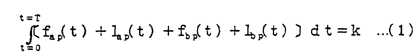
- the force components in the forward moving direction in the drawing of four forces fa(t), la(t), fb(t), which is a centrifugal force caused by the rotation pattern shown in Fig. 8(b), and lb(t), which is a force generated by controlling the locus of weight 2 so as to change pursuant to time t and the rotation pattern shown in Fig. 8(b), are set to fap(t), lap(t), fbp(t) and lbp(t), the rotational speed is sufficiently large, the weight is heavy and the forces fap(t), lap(t), fbp(t) and lbp(t) are dominant, the value k in the formula (1) may be a certain limited value instead of 0. If k is the limited value, the object will move at every round of rotation and will obtain the propulsive force.
- Fig. 1 is a schematic view showing an example of a rotation pattern of a rotational object in a propulsive force generation system in accordance with the present invention.
- there are four rotational objects in these example drawings and each pattern traced by the weight attached to the rotating rod in each of the four rotational objects, is to move as shown in Figs. 1(a), 1(b), 1(c) and 1(d). That is, the rotation pattern shown in Figs. 1(a) and 1(b) is controlled so that the locus of the weight 2 positioned at another end of the rod 1 which is attached to the rotational axis performs an oval movement of two-folds with large and small sizes, and the rotational directions of Figs.
- the pattern shown in Fig. 1(a) is called as an A pattern and the pattern shown in Fig. 1(b) is called as an A' pattern.
- a description will be in detail given below of this.
- the weight 2 on the large oval locus carries out a left rotation (counterclockwise rotation) on the drawing, and it shifts to the small ellipse orbit with a small rotation radius at lower part position in the drawing, and it is again returned to the large ellipse orbit mentioned above after one rotation of the small oval locus, and then reaches an initial position.
- the weight 2 carries out a right rotation (clockwise rotation) along a large ellipse and a small ellipse pattern in the drawing, and it shifts to the small ellipse orbit with a small rotation radius at the lower part position in the drawing in the same manner as that mentioned above, and it is again returned to the large ellipse orbit mentioned above after one rotation of the small oval locus, and then, reaches an initial position, that is, the weight 2 follows a reverse locus to the locus in Fig. 1(a).
- Figs. 1(c) and 1(d) show a uniform circular motion locus rotating in the opposite directions mutually, and are respectively called as a B pattern and a B' pattern.
- the rotation object (hereinafter, refer to as an A rotation object) which shows the A pattern mentioned above and the rotation object (hereinafter, refer to a B rotation object) which shows the B rotation pattern, are fixed on the same rotation axis. If the weight of the A rotation object starts from the large pattern of an ellipse locus, moves around the small pattern of an ellipse locus, returns again to the large pattern of the ellipse locus and finally reaches the original position during one rotation of the weight of the B rotation object.
- the A' rotation pattern in which the weight or the like is described in a symmetrical manner in a right side of the A rotation pattern with having a reverse rotation direction and the B' rotation pattern described in the same manner as A', cancel the force in the lateral direction with respect to the forward moving direction at a time of rotating the A and B rotation objects, and preventing from laterally oscillating.
- FIG. 2 is a schematic view showing one embodiment of a rotation mechanism in accordance with the present invention, which is an example of a principal part structure outline figure for drawing the loci of the double ellipse shown in Figs. 1(a) and 1(b) mentioned above, Fig.
- FIG. 2(a) is a plan view
- Fig. 2(b) is a side elevational view
- Fig. 2(c) is a partially detail view.
- the rotation object structure shown in this example is structured such that the weight 2 is added to one end of the rod 1 and the slit 4 having a desired length is provided in another end portion of the rod 1, and the center portion of the shaft 3 formed in a manner mentioned below extends through the slit 4, whereby the rod 1 is axially supported by the shaft 3 in a freely movable state.
- a partly linear gear (rack) 5 is formed in a side portion of the rod 1, and a circular gear (pinion) 6 is brought into contact with the rack 5 in a fitted manner.
- the rod 1 and the pinion 6 commonly rotate in an integral manner and the structure is made such that the rod 1 horizontally moves due to the rotation of the pinion.
- the motion can be easily understood by referring to Figs. 2(b) and 2(c). That is, Fig. 2(b) is a side elevational cross sectional view, and the weight 2 is fixed to one end of the rod 1, the rack 5 is formed on a side surface of the rod 1, and a stepping motor 7 is connected to a rotation axis of the pinion 6 fitted thereto.
- the stepping motor 7 is fixed to a plinth 10 of a cylinder body 9 supported to a body rotation axis 8 at upper and lower sides.
- the shaft 3 connected to the center portion of the cylinder body 9 and placed on the center of the cylinder body extends through the slit 4 at another end portion of the rod 1, but the structure is made, as shown in Fig. 2(c), such that a cut is formed in both sides of the slit penetrating portion of the shaft 3 and a cross sectional shape perpendicular to the shaft is formed in a rectangular shape.
- the structure is made such that the rotation of the shaft 3 connected to the body rotation axis 8 is transmitted to the rod 1, and the rod 1 freely moves in a longitudinal direction of the slit.
- Fig. 3 is a schematic view showing a mechanism structure example for generating a uniform rotation pattern shown in Figs. 1(c) and 1(d).
- a rotation rod 11 having one end connected to the rotation axis of the motor 7 is received within the cylinder body 9 supported by the body rotation axis 8 at the upper and lower sides, and the weight 2 is added to another end of the rotation rod 11.
- the motor 7 is fixed to the plinth of the cylinder body 9.
- another end of the rotation rod 11 may be only connected to the shaft 3 directly connected to the rotation axis 8 of the cylinder body 9 so as to secure the circular motion, but as in the present embodiment, in order to rotate in a complex period as the weight of the B and B' rotation object rotates one turn during two turns of the body rotation axis, it is advantageous that the motor 7 is provided as illustrated. However, in order to reduce the weight, the structure may be made such that the motor is removed and the rotation condition mentioned above is satisfied by the combination of the gears.
- Fig. 4 is a side elevational cross sectional view showing a state that four rotation objects are received within the same system.
- the structure is made such that a rotation drive circuit constituted by the electric motor and the gears and the like is provided in a rotation drive part 42 connected to a system case 41, and the B rotation object 44 and the A rotation object 45 mentioned above are arranged above in such a manner as to connect to the rotation axis 43 for transmitting the rotation of the motor, and the B' rotation object 47 and the A' rotation object 48 mentioned above are arranged below in such a manner as to connect to the rotation axis 46 connected to the motor in the same manner.
- the upper and lower rotation axes 43 and 46 are set to be mutually rotated in the reverse direction in Fig. 4.
- the composition in which four structures constituted by four rotation objects shown in Fig. 4 are arranged when the size of the rotation pattern of each of the rotation objects, the mass of each of the weights and the like are suitably set, the whole weight is about 21 kg, the mass of the weight is totally about 6 kg, and the B rotation object is rotated about three times at every one second, it was roughly confirmed that it moves at a speed of about 600 meters per hour.
- an energy conversion efficiency that is, an efficiency for converting a motor torque to a propulsive force in the system is not necessarily perfect as a theoretical manner, but if it is manufactured still with high precision, it is expected that much more efficient propulsive generation can be achieved.
- the mass of the weight mentioned above is set to be 10 times
- the rotation speed seen with the B rotation object is set to 30 times per second in this system, and the other conditions are set to be the same, the propulsive force will theoretically become 100 times or more times, and the apparatus propulsive speed will become significantly large.
- the propulsion system in accordance with the present invention requires an energy for rotating each of the rotation bodies, but since the system is not based on an action and reaction and move forward by the propulsion system itself without relating to the outside portion, the problems of the propulsion system in accordance with the conventional art mentioned above can be widely cancelled.
- Fig. 5 is a rotation pattern view for explaining another embodiment in accordance with the present invention.
- the rotation pattern shown in this example is called as a limason curve of Pascal. That is, even when using the pattern in accordance with the limason curve in place of the A and A' rotation patterns shown in Figs. 8(a), 1(a) and 1(b), it is possible to generate the propulsive force in the same manner as mentioned above.
- Fig. 6 shows an example of a rotation object structure for generating the limason curve, in which Fig. 6(a) is a plan view and Fig. 6(b) is a side elevational cross sectional view. That is, a first gear 64 is bonded to a support axis 63 extending through a center portion 62 of a cylinder body 61, and the support axis 63 is fixed to a vehicular object (solid) case (not shown) as shown in Fig. 6 (a), 6(b).
- a second gear 65 (called as a rotation gear) fitted and brought into contact with a peripheral gear of the first gear 64 mentioned above and having the same structure is arranged, but an axis 66 of the rotation gear 65 is rotatably pivoted to upper and lower portions of the cylinder body 61 by a bearing mechanism 67 such as a ball bearing or the like. Further, one end of a rod 68 having a desired length is fixed to the axis 66 of the second rotation gear, and a weight 69 having a desired mass is added to another end of the rod.
- a body axis 70 for rotating the cylinder body 61 is connected to the center portion in the lower portion of the cylinder body 61 in the same manner as that of the preceding embodiment.
- the structure may be made such that a simple flat plate is formed as the plinth and performs the same function as that of the embodiment mentioned above, in place of the cylinder body which receives the rod or the like to be rotated.
- the number of the mounted rotation obgects is not limited to four, and may be set to be equal to or less.
- the structure may be made such that a lot of rotation objects may be complicatedly combined.
- each of the rotation objects is arranged on the same axis, and various kinds of gears may be arranged on a flat surface in a combined manner.
- the present invention Since the present invention generates the propulsive force on the basis of the principle mentioned above, the friction between the rotating wheel and the ground or the rail does not relates to the propulsive force and the airjet or the like does not exist, as it is different from the conventional propulsion system, so that it is possible to prevent the wheel abrasion and the dust from being generated.
- the propulsive force is generated in accordance with the combination of the various kinds of rotation motions obtained in a comparatively easy manner, there is a high possibility that the energy efficiency becomes excellent in comparison with the conventional propulsive force generation system, and it is expected as epoch-making propulsive force means.
- the propulsive force generating direction can be changed to a desired direction only by shifting the rotation timing of each of the rotation objects a little. Accordingly, as is different from the conventional propulsive force generating means, it is possible to achieve a complex motion which can not be realized conventionally.
- the propulsive force can be generated as long as an electric power will be supplied if a motor is rotated with using this as an energy, so that it is preferable as a source of propulsive force, such as the flying objects for observing various kinds of stars in space.
Landscapes
- Engineering & Computer Science (AREA)
- Chemical & Material Sciences (AREA)
- Combustion & Propulsion (AREA)
- Mechanical Engineering (AREA)
- General Engineering & Computer Science (AREA)
- Linear Motors (AREA)
- Toys (AREA)
Abstract
The invention relates to a propulsive force
generation system with a new principle which is not on the
basis of the conventional action/reaction force defined as
the so-called Newton's third law, and provides a propulsive
force generation system which is usable for a flying object
such as a rocket and an airplane and for a vehicular object
such as a ship and a car, or for a driving force for a
construction machine or the like. The propulsive force
generation system is provided with one or a plurality of
rotational movement mechanism in the same object, and is
structured such that a propulsive force in an optional
direction is generated by controlling each rotational
movement patterns. The rotational movement mechanism is
structured such that a weight is engaged with another end
portion of a rod having one end rotatably pivoted and a
desired rotational movement pattern is generated by
changing a distance between the pivoted portion and the
weight in accordance with the rotation. Further, the
invention provides a vehicular object in which the
propulsive force generation system mentioned above is
mounted.
Description
The present invention relates to a propulsive force generation
system which is usable for a flying object such as a
rocket and an airplane and for a vehicular object such as a
ship and a car, or for a driving force for a construction machine
or the like and relates to a propulsive force generation
system with a new principle which is not on the basis of
the conventional action/reaction force defined as the so-called
Newton's third law.
As a conventional propulsion system for the flying objects,
there are a propulsion system on the basis of the
reaction from an air stream by a propeller, a system on the
basis of the reaction from an jet gas stream by an internal
combustion engine such as a jet engine, a rocket engine or
the like, and a system on the basis of the reaction from an
ion stream or a plasma stream.
Further, as a conventional propulsion system for a
ship, there is mainly employed the propulsion system on the
basis of the reaction from a water stream by a propeller, but
there is partly employed the same propulsion system as the
system for the flying objects or the propulsion system which
uses the reaction between the magnet laid on the ship and the
electrical current sent to the water around the ship.
Further, as a conventional propulsion system for the
land vehicular object such as a car, a streetcar or the like,
there is mainly employed the propulsion system on the basis
of the reaction from friction between the rotating wheels
mounted to the land vehicular object and the ground or between
the rotating wheels and the rails placed on the ground,
but there is partly employed the same propulsion system as
the system for the flying objects, or the propulsion system
which uses the reaction from the magnets laid on the earth.
However, the propulsion systems in accordance with the
conventional art mentioned above have the following problems.
That is, since the jet gas in the propulsion system using the
jet gas stream, or the ion or the plasma in the propulsion
system using respectively the ion stream or the plasma stream
is discharged from the flying objects or the like, the propulsive
force of the flying object will be lost when those
are consumed. Consequently, the time thrusting a rocket or a
space shuttle is limited by a quantity of the fuel producing
the jet gas. Further, the ion propulsive system used for
controlling a position of an artificial satellite generally
has a service life of about ten years due to a consumption of
the ion, and it determines the service life of the artificial
satellite. Particularly, as a propulsion system in the
space, there are known only the jet gas system and the plasma
or ion injecting systems mentioned above, so that there is a
disadvantage that the propulsive force is lost when the raw
material thereof is spent fully.
Further, it is not suitable for a high speed running in
respect of efficiency or the like in the propulsion system on
the basis of the air stream or the water stream by the propellers.
Further, in the propulsion system using the friction
with the ground or the rail, as well as there is generated a
noise pollution by the friction between the wheel and the
ground or the rail, and there is required a maintenance such
as a periodical repair and a replacement of the wheel, there
is a serious influence on our environment such as pollution
of dusts produced due to the wear and tear. Especially, in
the propulsion system using the friction between the rotating
wheel of the vehicular object and the ground or the rail and
the propulsion system on the basis of the air stream or the
water stream by the propellers, there is of course a disadvantage
giving a large influence to the generated propulsive
force due to a difference of the environmental condition of
the vehicular object, for example, an air density, a friction
coefficient or the like.
The present invention has been made in order to solve
many problems about the conventional propulsion system, and
an object of the present invention is to provide a propulsion
system and a vehicular object on the basis of a new principle,
which can solve the problems up to now and generate a
constant propulsive force without being influenced by an environmental
condition of the vehicular object, and a particular
object of the present invention is to provide a propulsion
system which can continue to generate a propulsive force
as long as an electric power supply source exist, since the
electric power supply source such as a solar battery can be
easily obtained in a space or the like.
In this case, many persons have deal with the same objects.
This fact is apparent from a lot of US patents and
Japanese Unexamined Patent Publications as shown in the later
stages.
However, there is no structure which can be actuated
with much regret. Most of US patents having the similar objects
to that of the present invention are structured such
that the propulsive force can be obtained by controlling by
some ways so as to increase a radius of rotation in the forward
moving direction in a rotational movement. The reasons
why the practical level can not be obtained are that no sufficient
propulsive force can be obtained, that a force in a
direction opposite to the forward moving direction is larger
than an average propulsive force and a violent vibration is
generated (since a large force in the opposite direction is
generated at a time of changing to a small radius of rotation
from a large radius of rotation in addition to a centrifugal
force of rotation), that a mechanism is complex and the like,
as shown in the background description in the patents. Some
patents propose a damper for absorbing a vibration.
Next, the patent specification and the publications in
U.S.A and Japan in 1976 -1999 which have the same object that
the propulsive force in one direction can be obtained from
the rotational movement can be exemplified as follows.
USP Nos. 3,968,700, 3,998,107, 4,095,460, 4,347,752, 4,579,011, 4,631,971, 4,712,439, 4,744,259, 4,770,063, 5,054,331, 5,156,058, 5,388,470, 5,488,877, 5,557,988, 5,791,188 and 5,890,400
USP Nos. 4,262,212, 4,991,453 and 5,167,163
USP Nos. 4,409,856, 4,479,396, 4,784,006 and 5,090,260
USP Nos. 4,856,358, 5,042,313 and 5,150,626
USP Nos. 4,238,968 and 5,937,698
Japanese Patent Application Laid-Open Nos. 56-66463, 56-146497, 59-6335, 63-13957, 7-49079, 8-284796 and 11-107905
Japanese Patent Application Laid-Open Nos. 55-51972, 55-72500, 56-31900, 56-53998, 61-233243 and 11-107908
Japanese Patent Application Laid-Open Nos. 56-106076, 59-8599, 60-56182, 62-101600, 62-198600, 2-501583, 6-101628 and 6-317247
Japanese Patent Application Laid-Open No. 64-66473
On the contrary, the propulsive force generation system
in accordance with the present invention is largely different
in view of the following points from the inventions described
in a lot of US patents and Japanese patent publications, and
corresponds to a structure which can be obtained by deeply
searching and considering.
In order to achieve the objects mentioned above, in accordance
with the present invention, there is provided a propulsive
force generation system characterized in that one or
a plurality of rotational movement mechanisms are provided in
the same object, and a propulsive force in a desired direction
is generated by controlling each rotational movement patterns
and additionally or differentially combining forces generated
due to the rotational movements having different rotation
patterns with respect to a propulsive direction, or
additionally and differentially combining the forces generated
due to the rotational movements having the different rotation
patterns with respect to the propulsive direction
(claim 1).
Further, as an embodiment in accordance with the present
invention, the above-mentioned rotational movement mechanism
is characterized by being structured such that a
weight is engaged with another end portion of a rod having
one end rotatably pivoted and a desired rotational movement
pattern is generated by changing a distance between the above-mentioned
pivoted portion and the above-mentioned weight
in accordance with the rotation (claim 2).
Further, in accordance with the present invention, there
is provided a vehicular object in which a propulsive force
generation system is mounted, characterized in that one or a
plurality of rotational movement mechanisms are provided in
the same object, and a propulsive force in a desired direction
is generated by controlling each rotational movement patterns
and additionally or differentially combining forces generated
due to the rotational movements having different rotation
patterns with respect to a propulsive direction, or
additionally and differentially combining the forces generated
due to the rotational movements having the different rotation
patterns with respect to the propulsive direction
(claim 3).
Further, as an embodiment of an embodiment in accordance
with the present invention, the above-mentioned rotational
movement mechanism is characterized by being structured such
that a weight is engaged with another end portion of a rod
having one end rotatably pivoted and a desired rotational movement
pattern is generated by changing a distance between
the above-mentioned pivoted portion and the above-mentioned
weight in accordance with the rotation (claim 4).
Further, in accordance with the present invention, there
is provided a propulsive force generation system characterized
in that a propulsive force in a desired direction is
generated by additionally or differentially combining forces
generated due to the rotational movements having one or a
plurality of Pascal's limason curve rotation patterns or a
similar rotation pattern and forces generated due to the rotational
movements having one or a plurality of other rotation
patterns with respect to a propulsive direction, or additionally
and differentially combining the forces generated
due to the rotational movements having one or a plurality of
Pascal's limason curve rotation patterns or the similar rotation
patterns and the forces generated due to the rotational
movements having one or a plurality of other rotation patterns
with respect to the propulsive direction (claim 5).
Further, in accordance with the present invention, there
is provided a vehicular object in which a propulsive force
generation system is mounted, characterized in that a propulsive
force in a desired direction is generated by additionally
or differentially combining forces generated due to the
rotational movements having one or a plurality of Pascal's
limason curve rotation patterns or a similar rotation patterns
and forces generated due to the rotational movements
having one or a plurality of other rotation patterns with
respect to a propulsive direction, or additionally and differentially
combining the forces generated due to the rotational
movements having one or a plurality of Pascal's limason
curve rotation patterns or the similar rotation patterns and
the forces generated due to the rotational movements having
one or a plurality of other rotation patterns with respect to
the propulsive direction (claim 6).
In summary of the structures mentioned above, the propulsion
system in accordance with the present invention is
structured such that the propulsive force can be obtained only
within the apparatus with having no structure for jetting
or discharging something to an external portion of the apparatus
and obtaining a force in connection with the external
portion, so that there is provided the propulsive force generation
apparatus characterized in that a plurality of rotational
objects, the means for controlling the rotation patterns
of the rotational objects and the drive means are provided
within the apparatus, and the vehicular object utilizing the
same.
A description will be in detail given below of the present
invention on the basis of an illustrated embodiment, but
prior to the description, the basic principle of the present
invention will be described at first with reference to Figs.
8 (a) and 8 (b).
That is, when one end of a stick (rod) with a required
length is axially fixed so as to be perpendicular to the rotational
axis of the motor or the like mounted to the movable
vehicular object and a heavy material (weight) having a required
mass is rotated in a state of being attached to another
end of the stick, a centrifugal force is generally generated
in the heavy material. For example, in the case of a
uniform circular motion as shown in Fig. 8(b), the centrifugal
force has the same magnitude in all the directions, so
that when the structure is made such that the object supporting
the rotational axis can freely move in all the directions,
the object can move in all the directions in accordance
with the centrifugal force, but is returned to the initial
position after one period of the circular motion and does not
move in one direction. The force applied to the rotational
axis for rotation the object is defined as lb(t). Further,
for example, even in the rotational movement having an oval
rotation pattern, when combining the centrifugal forces due
to the rotational movement and the force applied to the rotational
axis generated so as to obtain the oval pattern or the
like, the object supporting the rotational movement moves in
all the directions in accordance with the forces, but returns
to the initial position after one period of the rotational
movement and does not move in one direction.
Next, for example, a consideration will be given of the
case of the rotation pattern shown in Fig. 8(a), that is, the
case that one of a rod 1 is rotatably pivoted and a weight 2
is added to another end of the rod 1 and rotated. In this
case, when a consideration will be given of the case of being
controlled so that a distance between the weight 2 and a
shaft 3, that is, a rotational radius is reduced at each 120
degrees at a time of rotating one time (360 degrees), a force
applied to the rotary shaft 3 includes a centrifugal force
fa(t) in accordance with the rotation pattern, a force la(t)
generated by controlling so as to change a track of the
weight 2 together with a time t in correspondence to the rotation
pattern, a force generated from a drive side and the
like, and a predetermined deviating force is generated at
each of the rotational angles.
The inventor of the present invention has found that a
force applied in one direction, that is, a propulsive force
is generated by receiving two rotation patterns shown in
Figs. 8(a) and 8(b) in the same solid and suitably selecting
the masses ma and mb of the weights in the respective rotational
objects or the respective rotational patterns.
That is, when the force components in the forward moving
direction in the drawing of four forces fa(t), la(t),
fb(t), which is a centrifugal force caused by the rotation
pattern shown in Fig. 8(b), and lb(t), which is a force generated
by controlling the locus of weight 2 so as to change
pursuant to time t and the rotation pattern shown in Fig.
8(b), are set to fap(t), lap(t), fbp(t) and lbp(t), the rotational
speed is sufficiently large, the weight is heavy and
the forces fap(t), lap(t), fbp(t) and lbp(t) are dominant,
the value k in the formula (1) may be a certain limited value
instead of 0. If k is the limited value, the object will move
at every round of rotation and will obtain the propulsive
force.
It becomes advance which is generally called two step
advance one step retreat to the advance direction at every
round of rotation, in accordance with the principle, if the
pattern to a rotational object, the value of each weight and
the like are not set up ideally, but in the case that the
combination of the rotation pattern and the mass of each
weight is suitable, equipment which moves only in one direction
without retreating can be realized. In the experiment
actually performed, a limit exists in the rotational speed
and the mass of weight and a little amount of propulsive
force in the rearward moving direction remains, but if the
rotational speed is made high, various kinds of rotation patterns
are combined and the mass of weight is suitably set up,
a smooth propulsive force can be obtained mostly continuously.
The forward moving speed will be increased and reduced
in accordance with either or those combination of the size of
the rotation pattern, the mass of each heavy material
(weight), and the rotational speed.
As mentioned above, in accordance with the present invention,
since the structure is made such that the propulsive
force is generated in accordance with the motion of the rotation
mechanism received within the solid, and neither the
high speed air stream nor the water stream is generated outside
or the friction between the rotating wheel and the
ground or the rail is not generated as the conventional propulsion
system, many conventional problems can be sharply
solved.
A description will be in detail given below of the present
invention on the basis of the illustrated embodiment.
Fig. 1 is a schematic view showing an example of a rotation
pattern of a rotational object in a propulsive force
generation system in accordance with the present invention.
In this embodiment, there are four rotational objects in these
example drawings, and each pattern traced by the weight
attached to the rotating rod in each of the four rotational
objects, is to move as shown in Figs. 1(a), 1(b), 1(c) and
1(d). That is, the rotation pattern shown in Figs. 1(a) and
1(b) is controlled so that the locus of the weight 2 positioned
at another end of the rod 1 which is attached to the rotational
axis performs an oval movement of two-folds with
large and small sizes, and the rotational directions of Figs.
1(a) and 1(b) are mutually reverse. Hereinafter, the pattern
shown in Fig. 1(a) is called as an A pattern and the pattern
shown in Fig. 1(b) is called as an A' pattern. A description
will be in detail given below of this. In the A pattern in
Fig. 1(a), the weight 2 on the large oval locus carries out a
left rotation (counterclockwise rotation) on the drawing, and
it shifts to the small ellipse orbit with a small rotation
radius at lower part position in the drawing, and it is again
returned to the large ellipse orbit mentioned above after one
rotation of the small oval locus, and then reaches an initial
position. On the other hand, in the A' pattern in Fig. 1(b),
the weight 2 carries out a right rotation (clockwise rotation)
along a large ellipse and a small ellipse pattern in the
drawing, and it shifts to the small ellipse orbit with a
small rotation radius at the lower part position in the drawing
in the same manner as that mentioned above, and it is
again returned to the large ellipse orbit mentioned above after
one rotation of the small oval locus, and then, reaches
an initial position, that is, the weight 2 follows a reverse
locus to the locus in Fig. 1(a). On the other hand, Figs.
1(c) and 1(d) show a uniform circular motion locus rotating
in the opposite directions mutually, and are respectively
called as a B pattern and a B' pattern.
The rotation object (hereinafter, refer to as an A rotation
object) which shows the A pattern mentioned above and
the rotation object (hereinafter, refer to a B rotation object)
which shows the B rotation pattern, are fixed on the
same rotation axis. If the weight of the A rotation object
starts from the large pattern of an ellipse locus, moves around
the small pattern of an ellipse locus, returns again to
the large pattern of the ellipse locus and finally reaches
the original position during one rotation of the weight of
the B rotation object. That is, while the weight of the B
rotation object rotates once, the weight of the A rotation
object can rotate twice of the ellipse locus (there are large
and small sizes) by a synchronization, a propulsive force
will be generated in the required direction.
In this case, the A' rotation pattern in which the
weight or the like is described in a symmetrical manner in a
right side of the A rotation pattern with having a reverse
rotation direction, and the B' rotation pattern described in
the same manner as A', cancel the force in the lateral direction
with respect to the forward moving direction at a time
of rotating the A and B rotation objects, and preventing from
laterally oscillating.
When the applicant placed the rotational mechanisms
describing the rotation patterns mentioned above into the same
system and made it rotate, it becomes the movement that
repeats advance and some retreat, but it was confirmed that
the propulsive force was clearly produced in the upward direction
with respect to the drawing. In this case, there exist
structures shown in Figs. 2 and 3 as means for constituting
so that the loci as shown in Figs. 1(a) and 1(b) can be
drawn, though these are not restricted. That is, Fig. 2 is a
schematic view showing one embodiment of a rotation mechanism
in accordance with the present invention, which is an example
of a principal part structure outline figure for drawing the
loci of the double ellipse shown in Figs. 1(a) and 1(b) mentioned
above, Fig. 2(a) is a plan view, Fig. 2(b) is a side
elevational view and Fig. 2(c) is a partially detail view.
The rotation object structure shown in this example is structured
such that the weight 2 is added to one end of the rod 1
and the slit 4 having a desired length is provided in another
end portion of the rod 1, and the center portion of the shaft
3 formed in a manner mentioned below extends through the slit
4, whereby the rod 1 is axially supported by the shaft 3 in a
freely movable state.
Further, a partly linear gear (rack) 5 is formed in a
side portion of the rod 1, and a circular gear (pinion) 6 is
brought into contact with the rack 5 in a fitted manner. The
rod 1 and the pinion 6 commonly rotate in an integral manner
and the structure is made such that the rod 1 horizontally
moves due to the rotation of the pinion. The motion can be
easily understood by referring to Figs. 2(b) and 2(c). That
is, Fig. 2(b) is a side elevational cross sectional view, and
the weight 2 is fixed to one end of the rod 1, the rack 5 is
formed on a side surface of the rod 1, and a stepping motor 7
is connected to a rotation axis of the pinion 6 fitted thereto.
The stepping motor 7 is fixed to a plinth 10 of a cylinder
body 9 supported to a body rotation axis 8 at upper and
lower sides.
Further, the shaft 3 connected to the center portion of
the cylinder body 9 and placed on the center of the cylinder
body extends through the slit 4 at another end portion of the
rod 1, but the structure is made, as shown in Fig. 2(c), such
that a cut is formed in both sides of the slit penetrating
portion of the shaft 3 and a cross sectional shape perpendicular
to the shaft is formed in a rectangular shape. As a
result, the structure is made such that the rotation of the
shaft 3 connected to the body rotation axis 8 is transmitted
to the rod 1, and the rod 1 freely moves in a longitudinal
direction of the slit.
A description will be given of an operation in the
structure mentioned above. At first, when the body rotation
axis 8 is rotated by a second motor (which is omitted to be
illustrated), the shaft 3 is integrally rotated together with
the cylinder body 9, and the rotation motion is transmitted
to the rod 1 via the slit portion. When the rotation is continued
in this condition, the whole of the cylinder body 9 is
rotated with setting the distance between the center of the
shaft 3 and the weight 2 to a radius, in the rod, but when
further driving the stepping motor 7 in correspondence to the
rotation, the pinion 6 is rotated, and the distance between
the shaft 3 and the weight 2 changes due to the operation
with the rack 5 fitted thereto. Accordingly, when driving
the stepping motor at a predetermined cycle in synchronous
with the rotation of the cylinder body 9, it is possible to
create the rotation pattern of the rod shown in Figs. 1(a)
and 1(b).
Fig. 3 is a schematic view showing a mechanism structure
example for generating a uniform rotation pattern shown in
Figs. 1(c) and 1(d). In this example, in order to make the
same structure as that of the example shown in Fig. 2, a rotation
rod 11 having one end connected to the rotation axis
of the motor 7 is received within the cylinder body 9 supported
by the body rotation axis 8 at the upper and lower sides,
and the weight 2 is added to another end of the rotation rod
11. In this structure, the motor 7 is fixed to the plinth of
the cylinder body 9. In this case, since it is sufficient
that the B and B' rotation bodies perform the simple circular
motion, another end of the rotation rod 11 may be only connected
to the shaft 3 directly connected to the rotation axis
8 of the cylinder body 9 so as to secure the circular motion,
but as in the present embodiment, in order to rotate in a
complex period as the weight of the B and B' rotation object
rotates one turn during two turns of the body rotation axis,
it is advantageous that the motor 7 is provided as illustrated.
However, in order to reduce the weight, the structure
may be made such that the motor is removed and the rotation
condition mentioned above is satisfied by the combination of
the gears.
Fig. 4 is a side elevational cross sectional view showing
a state that four rotation objects are received within
the same system. The structure is made such that a rotation
drive circuit constituted by the electric motor and the gears
and the like is provided in a rotation drive part 42 connected
to a system case 41, and the B rotation object 44 and the
A rotation object 45 mentioned above are arranged above in
such a manner as to connect to the rotation axis 43 for
transmitting the rotation of the motor, and the B' rotation
object 47 and the A' rotation object 48 mentioned above are
arranged below in such a manner as to connect to the rotation
axis 46 connected to the motor in the same manner. In this
case, as already described, since the A and B rotation objects
and the A' and B' rotation objects should be mutually
rotated in the reverse direction, the upper and lower rotation
axes 43 and 46 are set to be mutually rotated in the reverse
direction in Fig. 4. In accordance with the experiment
of the applicant, the composition in which four structures
constituted by four rotation objects shown in Fig. 4 are arranged,
when the size of the rotation pattern of each of the
rotation objects, the mass of each of the weights and the like
are suitably set, the whole weight is about 21 kg, the
mass of the weight is totally about 6 kg, and the B rotation
object is rotated about three times at every one second, it
was roughly confirmed that it moves at a speed of about 600
meters per hour. In this experiment, a substantial speed was
calculated from observing results of the motion in the case
that experiment system put on casters on the base was run on
the plane covered by a board or the case that the system put
a vinyl sheet and performing a simple waterproofing was floated
on the water. In both cases, it was confirmed that the
substantially same propulsive force is generated. Further,
the experiment was not performed in a weightless vacuum condition,
but it is expected that the same propulsive force can
be obtained.
In this case, since the experiment mentioned above is
of a small scale and a manufacturing accuracy of the apparatus
or the like is imperfect, an energy conversion efficiency,
that is, an efficiency for converting a motor torque to a
propulsive force in the system is not necessarily perfect as
a theoretical manner, but if it is manufactured still with
high precision, it is expected that much more efficient propulsive
generation can be achieved. Further, even in the case
that the experimental conditions mentioned above are maintained,
when the mass of the weight mentioned above is set to
be 10 times, the rotation speed seen with the B rotation object
is set to 30 times per second in this system, and the
other conditions are set to be the same, the propulsive force
will theoretically become 100 times or more times, and the
apparatus propulsive speed will become significantly large.
The propulsion system in accordance with the present
invention requires an energy for rotating each of the rotation
bodies, but since the system is not based on an action and
reaction and move forward by the propulsion system itself
without relating to the outside portion, the problems of the
propulsion system in accordance with the conventional art
mentioned above can be widely cancelled.
Fig. 5 is a rotation pattern view for explaining another
embodiment in accordance with the present invention.
The rotation pattern shown in this example is called as a limason
curve of Pascal. That is, even when using the pattern
in accordance with the limason curve in place of the A and A'
rotation patterns shown in Figs. 8(a), 1(a) and 1(b), it is
possible to generate the propulsive force in the same manner
as mentioned above.
Fig. 6 shows an example of a rotation object structure
for generating the limason curve, in which Fig. 6(a) is a
plan view and Fig. 6(b) is a side elevational cross sectional
view. That is, a first gear 64 is bonded to a support axis
63 extending through a center portion 62 of a cylinder body
61, and the support axis 63 is fixed to a vehicular object
(solid) case (not shown) as shown in Fig. 6 (a), 6(b).
Further, a second gear 65 (called as a rotation gear) fitted
and brought into contact with a peripheral gear of the first
gear 64 mentioned above and having the same structure is arranged,
but an axis 66 of the rotation gear 65 is rotatably
pivoted to upper and lower portions of the cylinder body 61
by a bearing mechanism 67 such as a ball bearing or the like.
Further, one end of a rod 68 having a desired length is fixed
to the axis 66 of the second rotation gear, and a weight 69
having a desired mass is added to another end of the rod. In
this case, a body axis 70 for rotating the cylinder body 61
is connected to the center portion in the lower portion of
the cylinder body 61 in the same manner as that of the preceding
embodiment.
Here, when the body axis 70 is rotated at one time in
the structure constituted in this manner, the weight 69 added
to the rod 68 draws the limason curve as shown in Fig. 5(a).
Since a state that the weight 69 draws the limason curve can
be easily understood by referring to Fig. 7, the detailed
description will be omitted. Then, if those structures as
mentioned above are mounted in place of the A and A' rotation
bodies 45 and 48 in Fig. 4 and the rotation cycles of the B
and B' rotation bodies are made coincide with the rotation
cycles of the A and A' rotation bodies, it is possible to generate
the propulsive force in a predetermined direction in
the same manner.
Here, in the case of arranging the A and A' rotation
bodies shown in Fig. 6 so as to be overlapped with the B and
B' rotation bodies in the manner as shown in Fig. 4, since it
is necessary to fixe one end of the support axis 63 in Fig. 6
to the system (for example, the cylinder body 41 in Fig. 4),
the A rotation object and the B rotation object shown in Fig.
4 are replaced, the support axis of the A rotation object is
fixed to the ceiling of the cylinder body 41, the A' rotation
object and the B' rotation object disposed in the lower portion
are replaced and the support axis of the A' rotation object
is fixed to the bottom part of the cylinder body 41.
As mentioned above, the description is given of some
particular embodiments in accordance with the present invention,
but the structure is not limited to these embodiments
at a time of realizing the present invention, and various
kinds of modifications can be performed.
For example, the structure may be made such that a
simple flat plate is formed as the plinth and performs the
same function as that of the embodiment mentioned above, in
place of the cylinder body which receives the rod or the like
to be rotated. Further, the number of the mounted rotation
obgects is not limited to four, and may be set to be equal to
or less. Further, the structure may be made such that a lot
of rotation objects may be complicatedly combined.
Further, it is not necessary that each of the rotation
objects is arranged on the same axis, and various kinds of
gears may be arranged on a flat surface in a combined manner.
Since the present invention generates the propulsive
force on the basis of the principle mentioned above, the
friction between the rotating wheel and the ground or the
rail does not relates to the propulsive force and the airjet
or the like does not exist, as it is different from the conventional
propulsion system, so that it is possible to prevent
the wheel abrasion and the dust from being generated.
Further, since the propulsive force is generated in accordance
with the combination of the various kinds of rotation
motions obtained in a comparatively easy manner, there is
a high possibility that the energy efficiency becomes excellent
in comparison with the conventional propulsive force generation
system, and it is expected as epoch-making propulsive
force means.
Further, the propulsive force generating direction can
be changed to a desired direction only by shifting the rotation
timing of each of the rotation objects a little. Accordingly,
as is different from the conventional propulsive
force generating means, it is possible to achieve a complex
motion which can not be realized conventionally.
In particular, in space, since an electric power can be
easily obtained by the solar cell or the like, the propulsive
force can be generated as long as an electric power will be
supplied if a motor is rotated with using this as an energy,
so that it is preferable as a source of propulsive force,
such as the flying objects for observing various kinds of
stars in space.
Claims (6)
- A propulsive force generation system characterized in that one or a plurality of rotational movement mechanisms are provided in the same object, and a propulsive force in a desired direction is generated by controlling each roational movement pattern and additionally or differentially combining forces generated due to the rotational movements having different rotation patterns with respect to a propulsive direction, or additionally and differentially combining the forces generated due to the rotational movements having the different rotation patterns with respect to the propulsive direction.
- A propulsive force generation system as claimed in claim 1, characterized in that said rotational movement mechanism is structured such that a weight is engaged with another end portion of a rod having one end rotatably pivoted and a desired rotational movement pattern is generated by changing a distance between said pivoted portion and said weight in accordance with the rotation.
- A vehicular object in which a propulsive force generation system is mounted, characterized in that one or a plurality of rotational movement mechanisms are provided in the same object, and a propulsive force in a desired direction is generated by controlling each rotational movement pattern and additionally or differentially combining forces generated due to the rotational movements having different rotation patterns with respect to a propulsive direction, or additionally and differentially combining the forces generated due to the rotational movements having the different rotation patterns with respect to the propulsive direction.
- A vehicular object as claimed in claim 3, characterized in that said rotational movement mechanism is structured such that a weight is engaged with another end portion of a rod having one end rotatably pivoted and a desired rotational movement pattern is generated by changing a distance between said pivoted portion and said weight in accordance with the rotation.
- A propulsive force generation system characterized in that a propulsive force in a desired direction is generated by additionally or differentially combining forces generated due to the rotational movements having one or a plurality of Pascal's limason curve rotation patterns or a similar rotation patterns and forces generated due to the rotational movements having one or a plurality of other rotation patterns with respect to a propulsive direction, or additionally and differentially combining the forces generated due to the rotational movements having one or a plurality of Pascal's limason curve rotation patterns or the similar rotation patterns and the forces generated due to the rotational movements having one or a plurality of other rotation pattern with respect to the propulsive direction.
- A vehicular object in which a propulsive force generation system is mounted, characterized in that a propulsive force in a desired direction is generated by additionally or differentially combining forces generated due to the rotational movements having one or a plurality of Pascal's limason curve rotation pattern or a similar rotation pattern and forces generated due to the rotational movements having one or a plurality of other rotation pattern with respect to a propulsive direction, or additionally and differentially combining the forces generated due to the rotational movements having one or a plurality of Pascal's limason curve rotation pattern or the similar rotation pattern and the forces generated due to the rotational movements having one or a plurality of other rotation pattern with respect to the propulsive direction.
Applications Claiming Priority (3)
| Application Number | Priority Date | Filing Date | Title |
|---|---|---|---|
| JP19959299 | 1999-07-13 | ||
| JP19959299 | 1999-07-13 | ||
| PCT/JP2000/004587 WO2001004491A1 (en) | 1999-07-13 | 2000-07-10 | Thrust generating device and moving body |
Publications (2)
| Publication Number | Publication Date |
|---|---|
| EP1114930A1 true EP1114930A1 (en) | 2001-07-11 |
| EP1114930A4 EP1114930A4 (en) | 2005-10-12 |
Family
ID=16410424
Family Applications (1)
| Application Number | Title | Priority Date | Filing Date |
|---|---|---|---|
| EP00944368A Withdrawn EP1114930A4 (en) | 1999-07-13 | 2000-07-10 | PUSH GENERATING DEVICE AND MOBILE BODY |
Country Status (2)
| Country | Link |
|---|---|
| EP (1) | EP1114930A4 (en) |
| WO (1) | WO2001004491A1 (en) |
Cited By (2)
| Publication number | Priority date | Publication date | Assignee | Title |
|---|---|---|---|---|
| WO2003087574A1 (en) * | 2002-04-11 | 2003-10-23 | Btt Co., Ltd | Internal propulsion apparatus of closed system using a coriolis force |
| EP1681535A1 (en) * | 2005-01-18 | 2006-07-19 | Marina Lobova | Propulsion system |
Families Citing this family (1)
| Publication number | Priority date | Publication date | Assignee | Title |
|---|---|---|---|---|
| JP7678489B1 (en) | 2024-03-14 | 2025-05-16 | 株式会社ライトエンジ | Thrust generation method |
Family Cites Families (6)
| Publication number | Priority date | Publication date | Assignee | Title |
|---|---|---|---|---|
| FR2444172A2 (en) * | 1978-11-02 | 1980-07-11 | Canot Albert | Space engine using eccentric masses - has rotating wings giving gyroscopic stability and protection against meteorites |
| JPS59141704A (en) * | 1983-02-03 | 1984-08-14 | Osaka Fuji Kogyo Kk | Propelling motor |
| DE3830928A1 (en) * | 1988-09-12 | 1990-03-15 | Moser Karl | Thrust drive system |
| JPH0666245A (en) * | 1992-08-21 | 1994-03-08 | Yoshinori Itakura | Device for moving object by nonuniform curvilinear motion |
| US5335561A (en) * | 1992-10-23 | 1994-08-09 | James Harvey | Impulse converter |
| US5488877A (en) * | 1993-10-15 | 1996-02-06 | Lieurance; Richard L. | Centrifugal inertia drive |
-
2000
- 2000-07-10 WO PCT/JP2000/004587 patent/WO2001004491A1/en not_active Ceased
- 2000-07-10 EP EP00944368A patent/EP1114930A4/en not_active Withdrawn
Cited By (2)
| Publication number | Priority date | Publication date | Assignee | Title |
|---|---|---|---|---|
| WO2003087574A1 (en) * | 2002-04-11 | 2003-10-23 | Btt Co., Ltd | Internal propulsion apparatus of closed system using a coriolis force |
| EP1681535A1 (en) * | 2005-01-18 | 2006-07-19 | Marina Lobova | Propulsion system |
Also Published As
| Publication number | Publication date |
|---|---|
| EP1114930A4 (en) | 2005-10-12 |
| WO2001004491A1 (en) | 2001-01-18 |
Similar Documents
| Publication | Publication Date | Title |
|---|---|---|
| US3653269A (en) | Converting rotary motion into unidirectional motion | |
| US6561856B1 (en) | Power floating production and ship propulsion supported by gyroscope and energized by seas | |
| US20230167797A1 (en) | Eccentrically Rotating Mass Turbine | |
| CN1105422A (en) | Earth/Gyro Power Converter | |
| US20030047015A1 (en) | Centrifugal propulsion system | |
| EP1114930A1 (en) | Thrust generating device and moving body | |
| WO2005035363A1 (en) | A thruster for propelling and directing a vehicle without interacting with environment and method for making the same | |
| EP0027469B1 (en) | Unidirectional force generator | |
| US20080060460A1 (en) | Propulsion device employing conversion of rotary motion into a unidirectional linear force | |
| US7008276B1 (en) | Propulsion system | |
| US20040103728A1 (en) | Torque induced propulsion system | |
| US20040103729A1 (en) | Dual-axis centrifugal propulsion system | |
| US20050247145A1 (en) | Three-dimension motive machine | |
| RU2455187C1 (en) | Pulse-inertial propulsor (pip) and packaged pule-inertial propulsor (ppip) for transport facility | |
| WO2012046488A1 (en) | Propulsive-force generation device | |
| GB2426315A (en) | Propulsion by inertia | |
| US20110041630A1 (en) | Propulsion mechanism employing conversion of rotary motion into a unidirectional linear force | |
| WO2014185846A1 (en) | Device and method for gyroscopic propulsion | |
| JPWO2001004491A1 (en) | Thrust generating device and moving body | |
| RU2280513C2 (en) | Method of production of the directional oscillations, method of transformation of the directional mechanical oscillations into the unidirectional discontinuous translational movement, the method of the controlled movement of the transport vehicle in the preset direction and the devices for realization of these methods | |
| KR200211997Y1 (en) | Boat for reports | |
| KR100338326B1 (en) | Propulsive force producing method and device | |
| US20050169756A1 (en) | Inertial propeller | |
| CN116928049A (en) | Power generation device of electric flying operation state reciprocating rotation system in idle state of operation robot | |
| CN116857139A (en) | Running robot sea state ship (floating) running state system power generation device |
Legal Events
| Date | Code | Title | Description |
|---|---|---|---|
| PUAI | Public reference made under article 153(3) epc to a published international application that has entered the european phase |
Free format text: ORIGINAL CODE: 0009012 |
|
| 17P | Request for examination filed |
Effective date: 20010313 |
|
| AK | Designated contracting states |
Kind code of ref document: A1 Designated state(s): DE FR GB |
|
| A4 | Supplementary search report drawn up and despatched |
Effective date: 20050829 |
|
| STAA | Information on the status of an ep patent application or granted ep patent |
Free format text: STATUS: THE APPLICATION IS DEEMED TO BE WITHDRAWN |
|
| 18D | Application deemed to be withdrawn |
Effective date: 20060201 |