EP1114358B1 - Steuerungsvorrichtung zur einstellung eines betätigers - Google Patents
Steuerungsvorrichtung zur einstellung eines betätigers Download PDFInfo
- Publication number
- EP1114358B1 EP1114358B1 EP99951331A EP99951331A EP1114358B1 EP 1114358 B1 EP1114358 B1 EP 1114358B1 EP 99951331 A EP99951331 A EP 99951331A EP 99951331 A EP99951331 A EP 99951331A EP 1114358 B1 EP1114358 B1 EP 1114358B1
- Authority
- EP
- European Patent Office
- Prior art keywords
- control
- actuator
- valve
- adjusting
- control device
- Prior art date
- Legal status (The legal status is an assumption and is not a legal conclusion. Google has not performed a legal analysis and makes no representation as to the accuracy of the status listed.)
- Expired - Lifetime
Links
- 230000001105 regulatory effect Effects 0.000 claims abstract description 11
- 238000012544 monitoring process Methods 0.000 claims abstract description 6
- 230000001276 controlling effect Effects 0.000 claims abstract description 5
- 238000012937 correction Methods 0.000 claims abstract description 5
- 239000012530 fluid Substances 0.000 claims abstract 2
- 238000000034 method Methods 0.000 claims description 15
- 230000000694 effects Effects 0.000 claims description 5
- 238000001208 nuclear magnetic resonance pulse sequence Methods 0.000 claims description 5
- 239000007788 liquid Substances 0.000 claims description 3
- 230000004913 activation Effects 0.000 claims 1
- 238000012423 maintenance Methods 0.000 description 5
- 230000005540 biological transmission Effects 0.000 description 2
- 238000010586 diagram Methods 0.000 description 2
- 238000010276 construction Methods 0.000 description 1
- 238000005260 corrosion Methods 0.000 description 1
- 230000007797 corrosion Effects 0.000 description 1
- 238000013461 design Methods 0.000 description 1
- 238000001514 detection method Methods 0.000 description 1
- 239000000463 material Substances 0.000 description 1
- 239000012528 membrane Substances 0.000 description 1
- 238000012986 modification Methods 0.000 description 1
- 230000004048 modification Effects 0.000 description 1
- 238000012360 testing method Methods 0.000 description 1
Images
Classifications
-
- G—PHYSICS
- G05—CONTROLLING; REGULATING
- G05B—CONTROL OR REGULATING SYSTEMS IN GENERAL; FUNCTIONAL ELEMENTS OF SUCH SYSTEMS; MONITORING OR TESTING ARRANGEMENTS FOR SUCH SYSTEMS OR ELEMENTS
- G05B11/00—Automatic controllers
- G05B11/01—Automatic controllers electric
- G05B11/26—Automatic controllers electric in which the output signal is a pulse-train
Definitions
- the invention refers to a control device for adjusting an actuator, for control of a process, such as a valve adjustment in a process supply tube, which device comprises means for monitoring of the actual value of the actuator, and means for correction of this to a desired value.
- Control devices of the above mentioned type in which a measured actual value is compared with a desired value and which comprises means of correction, are previously known.
- the accuracy in said known systems is of the order of 0.5 %, which in many applications is not satisfactory. This accuracy can also vary depending on climate and temperature, If the control device is used in extremely warm environments or is exposed to intense sunlight, the material expansion can cause problems.
- US patent 5,634,885 describes a control device for a process flow valve.
- the control device comprises a sensor, which registers the actual value of the valve and delivers an analog electric signal corresponding to the actual position of the process flow valve to a comparator.
- the signal corresponding to the actual value is compared with an-electric desired signal from a control unit.
- the comparator transmits control signals corresponding to the difference between the actual and desired values for adjusting the solenoid valves, which in turn control the flow to an control device for adjusting the process flow valve.
- control device In the control device according to the US patent 5,654,885 the number of movable mechanical parts has been reduced compared to the above mentioned control device with mechanical balance control.
- the control device according to US 5,654,885 has some major shortcomings.
- the solenoid valves of the device can jam and even get stuck, which cause the control device to be non-operational.
- the control signals outputed to the solenoid valves do not provide the intended effect.
- a control device according to US 5,654,884 therefore requires much maintenance for satisfactory functioning.
- control device according to the invention is defined by claim 1.
- the said pulse sequence is able to rap valves which seize or have jamed less maintenance is required.
- control valve is provided with hand operating devices, with which the included valves can be controlled manually and entirely mechanically for adjusting the actuator to a desired position.
- control device can be emergency operated entirely manually during a power failure. This is not possible with previous known control devices.
- Hand operating devices also enable emergency operating during signal interruption, which allows the control device to be controlled manually during replacement or reparation of electrical components.
- a considerable advantage with hand operating devices for regulating of the control device is that an equipment during startup can be test run even before the control electronics are switched on. Shutdown in connection with fault detection, maintenance or reparation can often be avoided when there is a possibility of controlling a process with hand operating devices.
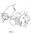
- Fig. 1 schematically shows a control device according to the invention for adjusting an actuator, which controls a flow valve.
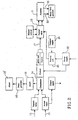
- Fig. 2 shows a block diagram, which schematically illustrates the parts of the device according to the invention.
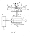
- Fig. 3 shows an embodiment of some pieces of the block diagram in Fig. 2.
- the control unit 1 has a casing 2, inside which is provided with a control valve, comprising a solenoid valve, and a circuit board with electrical components for controlling the device by input control signals according to the invention.
- the casing 1 is arranged on an actuator 3, which regulates the rotation of a shaft 4 for transmission of power, which is non-rotatably attached to a plate valve 5, which in turn regulates the flow A in a process supply tube 6.
- the adjustment of the actuator is controlled by a driving medium, which in the shown embodiment is compressed air. This is fed from a compressed source via a line 7 to the control unit 1, where the solenoid valve controls the flow of compressed air to and from the actuator.
- the lines with compressed air from the control unit 1 to the actuator has in Fig. 1 been indicated by reference numbers 8 and 9.
- the control unit 1 is supplied with power and the solenoid valve is controlled through control signals from an operating centre. Thus, the adjustment of the actuator is normally remote controlled.
- the device according to the invention is also provided with an emergency control system, with which the actuator can be controlled manually och entirely mechanically during an interruption of power supply and/or control signals.
- the emergency control system is ideally simpel.
- On the outside of the casing 1 is provided push buttons 10, 11, by means of which the solenoid valve can be directly controlled mechanically for regulating compressed air to the actuator.
- the control unit 1 is also provided with a position indicator 12, whose pointers are mechanically connected directly to the shaft 4 for transmission of power so that the position indicator always shows the position of the valve 5 and the amount of the process flow A.
- the actuator can easily be emergency controlled manually during voltage or signals failure.
- the control device normally works as schematically shown in Fig. 2.
- a potentiometer detects the actual value 13 of the actuator, which is transmitted to a comparator 14 in the control unit 1 and in the form of an out-put signal for remote reading of the actual value.
- a desired value 15 is fed to the comparator.
- the control signals 17 are transmitted to the control valve 3. It is provided with a solenoid valve, which is further described in connection with Fig. 3.
- the solenoid valve is controlled either by pulse modulation or three-point control. Pulse modulation gives a better accuracy in regulating the solenoid valve for adjusting the actuator.
- the control device comprises a first alarm 19. It is time controlled and activated after a certain time if a registered difference between the actual value and desired value has not been connected.
- the alarm effects a pulse generating circuit 19' which generates a pulse sequence to the solenoid valve to rap valves that have got stuck. If the registered difference between the actual value and desired value has not been corrected after a certain time after the generation of said pulse sequence a second alarm 19" is activated.
- the actuator has two mechanical limit switches 20, 21, one which for example can indicate totally closed valve 5 in the process flow tube and the other for example totally open valve.
- the limit switches 20, 21 are continously adjustable for arbitrary choice of desired limit positions. With help of the limit switches a clear indication is given that the actuator is in a chosen limit position.
- a reserve unit 23 is connected comprising a battery, which gives a pulse to the solenoid valve for adjusting the actuator to a desired predetermined position, for example totally opened or closed.
- the reserve unit 23 controls the actuator to said predetermined position.
- the pressure supply 24 of the driving medium for the actuator which in the shown embodiment consists of compressed air, is obtained by means of a not shown compressor.
- Fig. 3 shows a modified embodiment of the actuator 3' and a valve 5' controlled by it, in a process flow tube 6'.
- the actuator 3' consists of a cylinder and a piston 25 provided in it which is partly in connection partly with the valve 5' for its control and partly with a position indicator 26, which shows the actual value of the piston 25 and consequently of the valve 5'.
- the position indicator 26 suitably consists of a potentiometer which continuosly delivers an analoge actual value signal to the control unit 1.
- the solenoid valve which as a whole is referenced by 27, controls the flow of compressed air for regulating the piston 25 in the actuator 3'.
- the solenoid valve has three different adjustment positions. In one position, compressed air is fed via the line 28 to the cylinder space to the left of the piston, at which the piston is displaced to the right and moves the valve 5' in the opening direction.
- the compressed air is fed in opposite direction to the cylinder, i e the compressed air is fed via the line 29 to the cylinder space to the right of the piston 25, at which it is displaced to the left and brings the valve 5' in the closing direction.
- the supply channel is denoted by 30 and the air outlet-channels 31 and 32.
- Fig. 3 shows the solenoid valve in its third position, the-centre position. In this position the solenoid valve is closed and no compressed air can be fed to or from the cylinder space, but the piston remains in the adjusted position. Thanks to this design, compressed air is only consumed when the actuator is displaced for changing the adjustment of the valve 5'.
- the solenoid valve due to the pulse modulation can oscillate between its adjustment positions depending on the applied pulse frequency.
- the speed of the actuator can easily be regulated by means of throttle valves 33, 34 in the air outlet channels 31 and 32.
- Fig. 3 also shows the push buttons 10 and 11.
- the solenoid valves can be controlled manually and entirely mechanically by means of the push buttons 10,11.
- the solenoid valve is of the type five channels three ways valve with closed centre position.
- a solenoid valve of this type is displaced between its adjustment positions by compressed air, which flow direction for adjusting the valve is controlled by means of solenoid regulated seat valves. These seat valves can also be regulated manually with said push buttons 10, 11.
- the solenoid valve By pressing the push button 10 loaded by a spring provided in the push button the solenoid valve is placed in its first position, where feeding of compressed air is done via the line 28. When the push button is released the solenoid valve returns to its closed centre position by the effect of a not shown spring comprised in the solenoid valve. In a corresponding way, the inlet via the line 29 is controlled by the push button 11.
- the control device according to the invention is of course not limited to the above described actuator.
- This can be of arbitrary type, such as singel or dubble acting actuators with gas or liquid as driving medium.
- Fig. 3 a double acting actuator of cylinder type has been shown.
- the actuator according to Fig. 3 can be substituted by a single acting actuator of cylinder type with spring effect.
- an actuator in the form of a rotating device has been described.
- the actuator can be of membrane type.
Landscapes
- General Physics & Mathematics (AREA)
- Engineering & Computer Science (AREA)
- Automation & Control Theory (AREA)
- Physics & Mathematics (AREA)
- Fluid-Pressure Circuits (AREA)
- Servomotors (AREA)
- Flow Control (AREA)
- Fluid-Driven Valves (AREA)
- Magnetically Actuated Valves (AREA)
- Valve Device For Special Equipments (AREA)
- Control Of Throttle Valves Provided In The Intake System Or In The Exhaust System (AREA)
- Valve-Gear Or Valve Arrangements (AREA)
- Vehicle Body Suspensions (AREA)
- Fluid-Damping Devices (AREA)
Claims (8)
- Steuervorrichtung zur Einstellung eines Aktuators (3) zur Steuerung eines Prozesses, beispielsweise einer Ventileinstellung in einem Prozesszulaufrohr (6), wobei die Vorrichtung eine Einrichtung zur Anzeige des tatsächlichen Wertes des Aktuators und eine Einrichtung zur Korrektur dieses Wertes auf einen gewünschten Wert umfasst,
dadurch gekennzeichnet, dass ein Steuerventil (18) dazu ausgebildet ist, den Fluss des Antriebsmediums, beispielsweise einer Flüssigkeit oder eines Gases, für die Einstellung des Aktuators (3) zu steuern,
dass ein elektrischer Steuerstromkreis dazu ausgebildet ist, das Steuerventil zu regulieren, wenn der tatsächliche Wert vom gewünschten Wert abweicht, wobei eine Einrichtung zur Anzeige des tatsächlichen Wertes an den Steuerstromkreis angeschlossen ist,
dass das Steuerventil (18) ein Magnetventil (27) umfasst, das durch Impulsmodulation oder Drei-Punkt-Steuerung reguliert ist,
dass an den Steuerstromkreis ein erster Alarm (19) angeschlossen ist, dessen Aktivierung vorgesehen ist, wenn die Abweichung vom gewünschten Wert nicht innerhalb einer vorgegebenen Zeit korrigiert ist, dass die Steuereinheit nach Aktivierung des ersten Alarms dazu ausgebildet ist, eine Impulssequenz zu starten, die dazu bestimmt ist, auf das Steuerventil dahingehend einzuwirken, dass möglicherweise festsitzende oder geschlossene Ventile gelöst werden, und
dass die Vorrichtung eine Reserveeinheit umfasst, die eine Batterie (23) umfasst, wobei die Reserveeinheit während einer Unterbrechung von Betriebsspannung, Antriebsfluiden oder Steuersignalen einen Impuls an das Steuerventil (18) ausgibt zur Einstellung des Aktuators (3) auf eine vorgegebene Position, offen oder geschlossenen. - Steuervorrichtung nach Anspruch 1,
dadurch gekennzeichnet, dass das Steuerventil (18) mit einer Handbetriebseinrichtung (10, 11) versehen ist, die Ventile umfasst, die zur Einstellung des Aktuators (3) auf die gewünschte Position manuell und vollkommen mechanisch bedienbar sind. - Steuervorrichtung nach Anspruch 2,
dadurch gekennzeichnet, dass die Handbetriebseinrichtung (10, 11) Drucktasten umfasst, die gegen eine Federkraft drückbar sind zum Öffnen des jeweiligen Ventils. - Steuervorrichtung nach einem der vorhergehenden Ansprüche,
dadurch gekennzeichnet, dass die Vorrichtung mit einer Einrichtung zum Fernablesen versehen ist, um den Betriebszustand der Vorrichtung anzuzeigen. - Steuervorrichtung nach einem der vorhergehenden Ansprüche,
dadurch gekennzeichnet, dass eine Anzeigeeinrichtung (12; 26) mechanisch mit dem Aktuator (3; 3') verbunden ist, um seinen aktuellen Wert anzuzeigen. - Steuervorrichtung nach einem der vorhergehenden Ansprüche,
dadurch gekennzeichnet, dass zwei mechanische Grenzwertschalter (20, 21) in der Vorrichtung vorgesehen sind, die anzeigen, wenn die vorgegebenen Grenzwerte erreicht werden und die letztendlich dazu bestimmt sind, den Fluss des Antriebsmediums zu stoppen oder zu reduzieren, wenn der Aktuator die vorgegebenen Grenzwerte erreicht hat. - Steuervorrichtung nach einem der vorhergehenden Ansprüche,
dadurch gekennzeichnet, dass ein zweiter Alarm (19") in dem Steuerstromkreis vorgesehen ist, der aktiviert wird, wenn der gewünschte Wert nach einer vorbestimmten Zeit nach Ausgabe der Impulssequenz, die dazu bestimmt ist, möglicherweise festsitzende oder geschlossene Ventile zu lösen, nicht erreicht wird. - Steuervorrichtung nach einem der vorhergehenden Ansprüche, zur Einstellung eines Aktuators (3) zur Steuerung eines Prozesses, beispielsweise einer Ventileinstellung in einem Prozesszulaufrohr (6), wobei die Vorrichtung eine Einrichtung zur Anzeige des tatsächlichen Wertes des Aktuators und eine Einrichtung zur Korrektur dieses Wertes auf einen gewünschten Wert umfasst,
dadurch gekennzeichnet, dass eine Handbetriebseinrichtung (10, 11) vorgesehen ist, die dazu ausgebildet ist, normalerweise automatisch gesteuerte Steuerventile (18) während einer Unterbrechung von elektrischen Steuersignalen und/oder Betriebsspannung vollkommen mechanisch zu steuern, wobei die Ventile für die Flussregulierung eines Antriebsmediums, beispielsweise einer Flüssigkeit oder eines Gases, für die Einstellung des Aktuators (3) vorgesehen sind, der wiederum einen Prozess steuert, beispielsweise die Ventileinstellung in dem Prozesszulaufrohr (6).
Applications Claiming Priority (3)
| Application Number | Priority Date | Filing Date | Title |
|---|---|---|---|
| SE9803173 | 1998-09-18 | ||
| SE9803173A SE514848C2 (sv) | 1998-09-18 | 1998-09-18 | Styranordning för inställning av ett ställdon |
| PCT/SE1999/001625 WO2000017717A2 (en) | 1998-09-18 | 1999-09-17 | A control device for adjusting an actuator |
Publications (2)
| Publication Number | Publication Date |
|---|---|
| EP1114358A2 EP1114358A2 (de) | 2001-07-11 |
| EP1114358B1 true EP1114358B1 (de) | 2004-05-12 |
Family
ID=20412639
Family Applications (1)
| Application Number | Title | Priority Date | Filing Date |
|---|---|---|---|
| EP99951331A Expired - Lifetime EP1114358B1 (de) | 1998-09-18 | 1999-09-17 | Steuerungsvorrichtung zur einstellung eines betätigers |
Country Status (7)
| Country | Link |
|---|---|
| EP (1) | EP1114358B1 (de) |
| AT (1) | ATE266875T1 (de) |
| AU (1) | AU6379099A (de) |
| DE (1) | DE69917300T2 (de) |
| ES (1) | ES2221449T3 (de) |
| SE (1) | SE514848C2 (de) |
| WO (1) | WO2000017717A2 (de) |
Families Citing this family (2)
| Publication number | Priority date | Publication date | Assignee | Title |
|---|---|---|---|---|
| US9716792B2 (en) | 2015-10-19 | 2017-07-25 | Genesys Telecommunications Laboratories, Inc. | System and method for generating a network of contact center agents and customers for optimized routing of interactions |
| CN109765943B (zh) * | 2019-01-14 | 2021-01-15 | 东北大学 | 一种加热炉燃料阀门脉冲优化控制装置与方法 |
Family Cites Families (7)
| Publication number | Priority date | Publication date | Assignee | Title |
|---|---|---|---|---|
| GB1177496A (en) * | 1967-03-11 | 1970-01-14 | Paramatic Dev Ltd | Improvements in Control Systems. |
| CH600219A5 (en) * | 1974-11-02 | 1978-06-15 | Barmag Barmer Maschf | Hydraulic four-way control valve |
| DE2933780C2 (de) * | 1979-08-21 | 1986-07-10 | Messerschmitt-Bölkow-Blohm GmbH, 8000 München | Redundante Steuereinrichtung |
| US4430846A (en) * | 1982-01-15 | 1984-02-14 | Electro-Hydraulic Controls, Inc. | Electrohydraulic drive and control |
| SU1270476A1 (ru) * | 1983-09-07 | 1986-11-15 | Предприятие П/Я М-5168 | Система автоматического регулировани потоков загр зненных газов и жидкостей |
| US5654885A (en) * | 1995-03-28 | 1997-08-05 | Virginia Valve Company Corporation | Valve position controller |
| SE9503286L (sv) * | 1995-09-22 | 1997-03-17 | Alfa Laval Automation Ab | Förfarande samt reglersystem för friktionskomepensation |
-
1998
- 1998-09-18 SE SE9803173A patent/SE514848C2/sv unknown
-
1999
- 1999-09-17 AT AT99951331T patent/ATE266875T1/de not_active IP Right Cessation
- 1999-09-17 AU AU63790/99A patent/AU6379099A/en not_active Abandoned
- 1999-09-17 ES ES99951331T patent/ES2221449T3/es not_active Expired - Lifetime
- 1999-09-17 EP EP99951331A patent/EP1114358B1/de not_active Expired - Lifetime
- 1999-09-17 DE DE69917300T patent/DE69917300T2/de not_active Expired - Lifetime
- 1999-09-17 WO PCT/SE1999/001625 patent/WO2000017717A2/en not_active Ceased
Also Published As
| Publication number | Publication date |
|---|---|
| WO2000017717A3 (en) | 2000-05-25 |
| AU6379099A (en) | 2000-04-10 |
| ATE266875T1 (de) | 2004-05-15 |
| DE69917300D1 (de) | 2004-06-17 |
| EP1114358A2 (de) | 2001-07-11 |
| SE9803173L (sv) | 2000-03-19 |
| WO2000017717A2 (en) | 2000-03-30 |
| SE514848C2 (sv) | 2001-04-30 |
| SE9803173D0 (sv) | 1998-09-18 |
| DE69917300T2 (de) | 2005-06-02 |
| ES2221449T3 (es) | 2004-12-16 |
Similar Documents
| Publication | Publication Date | Title |
|---|---|---|
| US3924972A (en) | Control means for a variable capacity rotary screw compressor | |
| AU773739B2 (en) | A self-calibrating system and method for controlling a hydraulically operated device | |
| IL150073A (en) | Electronic method for preparing mixed water | |
| US4080110A (en) | Control system for variable capacity gas compressor | |
| EP2085852A2 (de) | Zeitimpulssteuerventil für Druckregelventil | |
| US4798531A (en) | Process and apparatus for the control of the air and fuel supply to a plurality of burners | |
| GB2292234A (en) | Position controller for a servo drive | |
| US4768548A (en) | Pressure reducer | |
| US20010035512A1 (en) | Environmentally friendly electro-pneumatic positioner | |
| JP2001504927A (ja) | 障害時固定式ゼロドリフトアクチュエータ | |
| EP1114358B1 (de) | Steuerungsvorrichtung zur einstellung eines betätigers | |
| CA1041401A (en) | Pipe-rupture safety device for natural-gas lines and the like | |
| US3482588A (en) | Electrically modulated pressure regulating and monitoring means | |
| US4219181A (en) | Fluid flow governing valve means | |
| RU2736443C2 (ru) | Устройство (варианты) для независимого управления усилиями для посадки в поворотных клапанах | |
| EP0202413A1 (de) | Klebepistole mit ferngesteuerter Durchflussregelung | |
| NO842080L (no) | Ventil-omformer/innstiller med fjerntilbakekopling og hukommelse | |
| JPH01153878A (ja) | ガスガバナ装置 | |
| US5918526A (en) | Method in a pneumatic oscillating device to observe an obstacle and to continue oscillating and corresponding oscillating device | |
| US3602241A (en) | Pneumatic control system and reset valve for such a system or the like | |
| CA1058129A (en) | Control system for variable capacity gas compressor | |
| KR100264564B1 (ko) | 솔레노이드 밸브의 모니터링 장치 및 그 제어방법 | |
| EP4641346A1 (de) | Druckregelsystem | |
| JPH02123406A (ja) | 圧力制御弁 | |
| JP2006134316A (ja) | 圧縮空気の圧力を連続的に調整する空圧装置 |
Legal Events
| Date | Code | Title | Description |
|---|---|---|---|
| PUAI | Public reference made under article 153(3) epc to a published international application that has entered the european phase |
Free format text: ORIGINAL CODE: 0009012 |
|
| 17P | Request for examination filed |
Effective date: 20010316 |
|
| AK | Designated contracting states |
Kind code of ref document: A2 Designated state(s): AT BE CH CY DE DK ES FI FR GB GR IE IT LI LU MC NL PT SE |
|
| GRAP | Despatch of communication of intention to grant a patent |
Free format text: ORIGINAL CODE: EPIDOSNIGR1 |
|
| GRAS | Grant fee paid |
Free format text: ORIGINAL CODE: EPIDOSNIGR3 |
|
| GRAA | (expected) grant |
Free format text: ORIGINAL CODE: 0009210 |
|
| RAP1 | Party data changed (applicant data changed or rights of an application transferred) |
Owner name: PROCESS INOVATION AB |
|
| RIN1 | Information on inventor provided before grant (corrected) |
Inventor name: BUHR, STAFFAN |
|
| AK | Designated contracting states |
Kind code of ref document: B1 Designated state(s): AT BE CH CY DE DK ES FI FR GB GR IE IT LI LU MC NL PT SE |
|
| PG25 | Lapsed in a contracting state [announced via postgrant information from national office to epo] |
Ref country code: NL Free format text: LAPSE BECAUSE OF FAILURE TO SUBMIT A TRANSLATION OF THE DESCRIPTION OR TO PAY THE FEE WITHIN THE PRESCRIBED TIME-LIMIT Effective date: 20040512 Ref country code: LI Free format text: LAPSE BECAUSE OF FAILURE TO SUBMIT A TRANSLATION OF THE DESCRIPTION OR TO PAY THE FEE WITHIN THE PRESCRIBED TIME-LIMIT Effective date: 20040512 Ref country code: FI Free format text: LAPSE BECAUSE OF FAILURE TO SUBMIT A TRANSLATION OF THE DESCRIPTION OR TO PAY THE FEE WITHIN THE PRESCRIBED TIME-LIMIT Effective date: 20040512 Ref country code: CY Free format text: LAPSE BECAUSE OF FAILURE TO SUBMIT A TRANSLATION OF THE DESCRIPTION OR TO PAY THE FEE WITHIN THE PRESCRIBED TIME-LIMIT Effective date: 20040512 Ref country code: CH Free format text: LAPSE BECAUSE OF FAILURE TO SUBMIT A TRANSLATION OF THE DESCRIPTION OR TO PAY THE FEE WITHIN THE PRESCRIBED TIME-LIMIT Effective date: 20040512 Ref country code: BE Free format text: LAPSE BECAUSE OF FAILURE TO SUBMIT A TRANSLATION OF THE DESCRIPTION OR TO PAY THE FEE WITHIN THE PRESCRIBED TIME-LIMIT Effective date: 20040512 Ref country code: AT Free format text: LAPSE BECAUSE OF FAILURE TO SUBMIT A TRANSLATION OF THE DESCRIPTION OR TO PAY THE FEE WITHIN THE PRESCRIBED TIME-LIMIT Effective date: 20040512 |
|
| REG | Reference to a national code |
Ref country code: GB Ref legal event code: FG4D |
|
| REG | Reference to a national code |
Ref country code: CH Ref legal event code: EP |
|
| REG | Reference to a national code |
Ref country code: IE Ref legal event code: FG4D |
|
| REF | Corresponds to: |
Ref document number: 69917300 Country of ref document: DE Date of ref document: 20040617 Kind code of ref document: P |
|
| PG25 | Lapsed in a contracting state [announced via postgrant information from national office to epo] |
Ref country code: SE Free format text: LAPSE BECAUSE OF FAILURE TO SUBMIT A TRANSLATION OF THE DESCRIPTION OR TO PAY THE FEE WITHIN THE PRESCRIBED TIME-LIMIT Effective date: 20040812 Ref country code: GR Free format text: LAPSE BECAUSE OF FAILURE TO SUBMIT A TRANSLATION OF THE DESCRIPTION OR TO PAY THE FEE WITHIN THE PRESCRIBED TIME-LIMIT Effective date: 20040812 Ref country code: DK Free format text: LAPSE BECAUSE OF FAILURE TO SUBMIT A TRANSLATION OF THE DESCRIPTION OR TO PAY THE FEE WITHIN THE PRESCRIBED TIME-LIMIT Effective date: 20040812 |
|
| PG25 | Lapsed in a contracting state [announced via postgrant information from national office to epo] |
Ref country code: LU Free format text: LAPSE BECAUSE OF NON-PAYMENT OF DUE FEES Effective date: 20040917 Ref country code: IE Free format text: LAPSE BECAUSE OF NON-PAYMENT OF DUE FEES Effective date: 20040917 |
|
| PG25 | Lapsed in a contracting state [announced via postgrant information from national office to epo] |
Ref country code: MC Free format text: LAPSE BECAUSE OF NON-PAYMENT OF DUE FEES Effective date: 20040930 |
|
| NLV1 | Nl: lapsed or annulled due to failure to fulfill the requirements of art. 29p and 29m of the patents act | ||
| REG | Reference to a national code |
Ref country code: CH Ref legal event code: PL |
|
| REG | Reference to a national code |
Ref country code: ES Ref legal event code: FG2A Ref document number: 2221449 Country of ref document: ES Kind code of ref document: T3 |
|
| ET | Fr: translation filed | ||
| PLBE | No opposition filed within time limit |
Free format text: ORIGINAL CODE: 0009261 |
|
| STAA | Information on the status of an ep patent application or granted ep patent |
Free format text: STATUS: NO OPPOSITION FILED WITHIN TIME LIMIT |
|
| 26N | No opposition filed |
Effective date: 20050215 |
|
| REG | Reference to a national code |
Ref country code: IE Ref legal event code: MM4A |
|
| PG25 | Lapsed in a contracting state [announced via postgrant information from national office to epo] |
Ref country code: PT Free format text: LAPSE BECAUSE OF NON-PAYMENT OF DUE FEES Effective date: 20041012 |
|
| PGFP | Annual fee paid to national office [announced via postgrant information from national office to epo] |
Ref country code: DE Payment date: 20140922 Year of fee payment: 16 |
|
| PGFP | Annual fee paid to national office [announced via postgrant information from national office to epo] |
Ref country code: GB Payment date: 20140919 Year of fee payment: 16 Ref country code: FR Payment date: 20140919 Year of fee payment: 16 Ref country code: ES Payment date: 20140926 Year of fee payment: 16 |
|
| PGFP | Annual fee paid to national office [announced via postgrant information from national office to epo] |
Ref country code: IT Payment date: 20140929 Year of fee payment: 16 |
|
| REG | Reference to a national code |
Ref country code: DE Ref legal event code: R119 Ref document number: 69917300 Country of ref document: DE |
|
| PG25 | Lapsed in a contracting state [announced via postgrant information from national office to epo] |
Ref country code: IT Free format text: LAPSE BECAUSE OF NON-PAYMENT OF DUE FEES Effective date: 20150917 |
|
| GBPC | Gb: european patent ceased through non-payment of renewal fee |
Effective date: 20150917 |
|
| REG | Reference to a national code |
Ref country code: FR Ref legal event code: ST Effective date: 20160531 |
|
| PG25 | Lapsed in a contracting state [announced via postgrant information from national office to epo] |
Ref country code: GB Free format text: LAPSE BECAUSE OF NON-PAYMENT OF DUE FEES Effective date: 20150917 Ref country code: DE Free format text: LAPSE BECAUSE OF NON-PAYMENT OF DUE FEES Effective date: 20160401 |
|
| PG25 | Lapsed in a contracting state [announced via postgrant information from national office to epo] |
Ref country code: FR Free format text: LAPSE BECAUSE OF NON-PAYMENT OF DUE FEES Effective date: 20150930 |
|
| REG | Reference to a national code |
Ref country code: ES Ref legal event code: FD2A Effective date: 20161026 |
|
| PG25 | Lapsed in a contracting state [announced via postgrant information from national office to epo] |
Ref country code: ES Free format text: LAPSE BECAUSE OF NON-PAYMENT OF DUE FEES Effective date: 20150918 |