EP1113272A2 - Acceleration sensor, acceleration sensor device, and method of fabricating an acceleration sensor - Google Patents
Acceleration sensor, acceleration sensor device, and method of fabricating an acceleration sensor Download PDFInfo
- Publication number
- EP1113272A2 EP1113272A2 EP00403340A EP00403340A EP1113272A2 EP 1113272 A2 EP1113272 A2 EP 1113272A2 EP 00403340 A EP00403340 A EP 00403340A EP 00403340 A EP00403340 A EP 00403340A EP 1113272 A2 EP1113272 A2 EP 1113272A2
- Authority
- EP
- European Patent Office
- Prior art keywords
- vibrator
- acceleration sensor
- weight section
- set forth
- weight
- Prior art date
- Legal status (The legal status is an assumption and is not a legal conclusion. Google has not performed a legal analysis and makes no representation as to the accuracy of the status listed.)
- Withdrawn
Links
Images





















Classifications
-
- G—PHYSICS
- G01—MEASURING; TESTING
- G01P—MEASURING LINEAR OR ANGULAR SPEED, ACCELERATION, DECELERATION, OR SHOCK; INDICATING PRESENCE, ABSENCE, OR DIRECTION, OF MOVEMENT
- G01P15/00—Measuring acceleration; Measuring deceleration; Measuring shock, i.e. sudden change of acceleration
- G01P15/02—Measuring acceleration; Measuring deceleration; Measuring shock, i.e. sudden change of acceleration by making use of inertia forces using solid seismic masses
- G01P15/08—Measuring acceleration; Measuring deceleration; Measuring shock, i.e. sudden change of acceleration by making use of inertia forces using solid seismic masses with conversion into electric or magnetic values
- G01P15/09—Measuring acceleration; Measuring deceleration; Measuring shock, i.e. sudden change of acceleration by making use of inertia forces using solid seismic masses with conversion into electric or magnetic values by piezoelectric pick-up
-
- G—PHYSICS
- G01—MEASURING; TESTING
- G01P—MEASURING LINEAR OR ANGULAR SPEED, ACCELERATION, DECELERATION, OR SHOCK; INDICATING PRESENCE, ABSENCE, OR DIRECTION, OF MOVEMENT
- G01P15/00—Measuring acceleration; Measuring deceleration; Measuring shock, i.e. sudden change of acceleration
- G01P15/02—Measuring acceleration; Measuring deceleration; Measuring shock, i.e. sudden change of acceleration by making use of inertia forces using solid seismic masses
- G01P15/08—Measuring acceleration; Measuring deceleration; Measuring shock, i.e. sudden change of acceleration by making use of inertia forces using solid seismic masses with conversion into electric or magnetic values
- G01P15/097—Measuring acceleration; Measuring deceleration; Measuring shock, i.e. sudden change of acceleration by making use of inertia forces using solid seismic masses with conversion into electric or magnetic values by vibratory elements
-
- G—PHYSICS
- G01—MEASURING; TESTING
- G01P—MEASURING LINEAR OR ANGULAR SPEED, ACCELERATION, DECELERATION, OR SHOCK; INDICATING PRESENCE, ABSENCE, OR DIRECTION, OF MOVEMENT
- G01P15/00—Measuring acceleration; Measuring deceleration; Measuring shock, i.e. sudden change of acceleration
- G01P15/02—Measuring acceleration; Measuring deceleration; Measuring shock, i.e. sudden change of acceleration by making use of inertia forces using solid seismic masses
- G01P15/08—Measuring acceleration; Measuring deceleration; Measuring shock, i.e. sudden change of acceleration by making use of inertia forces using solid seismic masses with conversion into electric or magnetic values
- G01P15/09—Measuring acceleration; Measuring deceleration; Measuring shock, i.e. sudden change of acceleration by making use of inertia forces using solid seismic masses with conversion into electric or magnetic values by piezoelectric pick-up
- G01P15/0915—Measuring acceleration; Measuring deceleration; Measuring shock, i.e. sudden change of acceleration by making use of inertia forces using solid seismic masses with conversion into electric or magnetic values by piezoelectric pick-up of the shear mode type
Definitions
- the present invention relates to an acceleration sensor for detecting an acceleration, and more particularly to an acceleration sensor for detecting an acceleration by sliding vibration, which is exerted when an acceleration is applied, and to an acceleration sensor device constructed by storing this acceleration sensor in a package.
- An acceleration sensor is installed in equipment to monitor an abnormal condition of the equipment by detecting an acceleration and vibration of the equipment.
- the acceleration sensor is used to prevent errors in reading and writing data resulting from vibration and shock in a hard disk drive, to prevent hand shaking in a video camera, to actuate an air bag in a vehicle, etc.
- an acceleration sensor using a piezoelectric element has been conventionally put into practice.
- Disclosed examples of such an acceleration sensor include an acceleration sensor which detects an acceleration by using a deflection of a piezoelectric single crystal (Japanese Patent Application Laid-Open Nos. 10-206456/1998 and 11-211748/1999) and an acceleration sensor which detects an acceleration by using a deflection of piezoelectric ceramic (Japanese Patent Application Laid-Open No. 6-273439/1994).
- Acceleration sensors using the deflection of a piezoelectric single crystal or the deflection of piezoelectric ceramic as mentioned above can improve the detection sensitivity by increasing the deflection to increase the stress.
- the mass needs to be increased to produce a larger deflection, causing a problem that the acceleration sensor becomes heavier and larger in size.
- the piezoelectric element is made thicker, it does not easily deflect and causes a problem that the detection sensitivity is lowered.
- such proposals are associated with problems that the fabrication process is complicated and the cost is increased.
- the applicant of the present invention proposed an acceleration sensor capable of detecting an acceleration with good sensitivity by a small-sized structure (Japanese Patent Application Laid-Open No. 2000-97707).
- This acceleration sensor comprises a vibrator and a weight section which is connected and supported at a position different from the position of the center of gravity of an assembly of the vibrator and weight section, and obtains the magnitude of an applied acceleration by detecting the amount of characteristic (sliding vibration) of the vibrator corresponding to an angular moment exerted in the weight section when the acceleration is applied.
- the present inventors are pursuing the development and improvement of such an acceleration sensor that has a small-sized structure and a high detection sensitivity without increasing the size of the vibrator to achieve high performance because it detects sliding vibration instead of deflective vibration.
- the present invention has been achieved in view of the above-mentioned circumstance, and its object is to provide an acceleration sensor which is an improvement of the acceleration sensor proposed in Japanese Patent Application Laid-Open No. 2000-97707 and capable of realizing a further reduction in size and cost while maintaining high performance.
- Another object of the present invention is to provide an acceleration sensor which does not limit sliding vibration of a vibrator for the purpose of preventing a lowering of the detection performance.
- Still another object of the present invention is to provide an acceleration sensor capable of improving the connectivity between a vibrator and a weight section.
- Yet another object of the present invention is to provide an acceleration sensor device having a package structure capable of storing such an acceleration sensor efficiently without deteriorating its detection performance.
- An acceleration sensor of the first aspect of the present invention comprises a vibrator provided with an electrode and subject to a sliding vibration; and a weight section connected to the vibrator and supported at a position different from the position of the center of gravity of an assembly of the vibrator and weight section, wherein the weight section is provided with a wiring pattern connected to the electrode, the vibrator detects an angular moment about the support point as sliding vibration, which is exerted in the weight section when an acceleration is applied, and an electrical signal corresponding to the applied acceleration is output from the electrode through the wiring pattern.
- the weight section is provided with the wiring pattern for drawing an electrical signal corresponding to an acceleration to be detected, and also functions as a signal detecting substrate. Therefore, it is not necessary to newly provide a signal detecting substrate, resulting in a simplified structure and a reduction in the cost.
- a detection portion for sliding vibration of the vibrator is divided by electrodes which are a plurality of divided electrode parts. Since the detection portion for sliding vibration of the vibrator is divided into a plurality of parts by the electrodes, the detection section of the vibrator can be divided simply, thereby achieving a reduction in the cost.
- the detection portion for sliding vibration of the vibrator is divided by the electrodes which are a plurality of divided electrode parts and by a groove connected to the electrodes. Since the detection portion for sliding vibration of the vibrator is divided into a plurality of parts by the formation of the groove, the detection portion of the vibrator is certainly divided and a number of acceleration sensors are readily manufactured, thereby achieving a reduction in the cost.
- the vibrator has substantially a rectangular parallelepiped shape, and the groove has a depth of not less than 10% of the thickness of the vibrator. Since the groove is formed to have a depth of not less than 10% of the thickness of the vibrator in the process of dividing the detection portion of the vibrator into a plurality of parts by the formation of the groove, it is possible to achieve not only a reduction in the cost, but also an improvement in the detection sensitivity.
- a position where the detection portion is divided is a position where a charge distribution by the sliding vibration is substantially zero. Since the detection portion of the vibrator is divided at a position where the angular moment of the weight section is substantially zero, i.e., a position where the charge distribution by the sliding vibration of the vibrator is substantially zero, it is possible to achieve not only a reduction in the cost, but also an improvement in the detection sensitivity.
- the vibrator and weight section have substantially a rectangular parallelepiped shape, and a length (width) of the vibrator in an acceleration detecting direction is not more than a length (width) of the weight section in the acceleration detecting direction. It is therefore possible to reduce an error signal (crosstalk) generated when an acceleration in a direction different from that of an acceleration to be detected is applied, and to improve the S/N ratio.
- the weight section has substantially a rectangular parallelepiped shape, and has greater thickness and/or length (width) in an acceleration detecting direction in its portion on one side opposite to the other side connected to the vibrator than in its portion on the other side.
- the thickness and/or the width of the portion on the side opposite to the vibrator side including the support position is made greater, it is possible to increase the angular moment of the weight section and improve the detection sensitivity.
- the weight section is constituted by a plurality of members of different materials. It is therefore possible to select the constituent materials of the weight section so as to increase the angular moment of the weight section and improve the detection sensitivity.
- the weight section has a higher density in its portion on one side opposite to the other side connected to the vibrator than in its portion on the other side. Since the weight section is constructed by using a high-dense material for the portion on the side opposite to the vibrator side, the angular moment of the weight section is increased, thereby improving the detection sensitivity.
- the vibrator is bonded to the weight section with an anisotropic conductive adhesive. Since the vibrator and the weight section are bonded together with the anisotropic conductive adhesive, it is possible to prevent a short circuit between the divided electrodes, provide a satisfactory connection between the vibrator and weight section, and achieve conductivity only in a desired direction.
- the electrical signal is drawn from one of the divided electrodes of the vibrator, which is closer to the position of the center of gravity. Since an acceleration is not detected by a differential output of both the divided electrodes of the vibrator (a differential electrical signal of both the electrodes), but is detected by only the output (electrical signal) of one of the divided electrodes, which is closer to the position of the center of gravity, the number of patterns to be formed in the detection circuit is reduced, thereby achieving a reduction in the cost.
- the thinnest portion of the weight section having a substantially rectangular parallelepiped shape is not located on one side of the position of the vibrator, including the position of the center of gravity. Since the thinnest portion of the weight section is placed on the vibrator or on a position extended from the vibrator in a direction opposite to a direction toward the position of the center of gravity, it is possible to reduce crosstalk and improve the S/N ratio.
- the inside of the groove should be kept in a hollow state.
- the inside of the groove is kept in a hollow state by bonding the vibrator and weight section with an anisotropic conductive film.
- a protruding portion with a width of not less than the width of the groove is formed on the weight section, at a position facing the groove, and the groove is covered with the protruding portion, thereby keeping the inside of the groove in a hollow state.
- the vibrator and weight section are bonded together with an adhesive, and the groove is filled with a filler whose Young's modulus is smaller than that of the adhesive.
- the inside of the groove is in a hollow state, certainly sliding vibration is not limited.
- the process of producing the hollow state is not easy by any means, and it is also hard to say that the process of connecting the vibrator and weight section with an adhesive while maintaining the hollow state is easy.
- the groove is filled with some filler, if the hardness of the filler is low, sliding vibration is hardly limited. Therefore, the groove is filled with a filler whose Young's modulus is smaller than that of an adhesive used for connecting the vibrator and weight section. In this case, it is possible to minimize the deterioration of the detection performance and readily perform the process of connecting the vibrator and weight section with an adhesive.
- the groove has a width greater than the widths of the divided detection portions of the vibrator. Since the width of the groove of the vibrator is made greater than the widths of the respective portions where the electrodes are formed, the bonded area other than the electrodes is increased, thereby improving the resistance to shock.
- the vibrator and the weight section are bonded together with an adhesive, and the area of this bonded face is greater than the area of the electrode and/or the wiring pattern. Since the area of the electrode and/or the wiring pattern is made smaller than the bonded area between the vibrator and weight section, even when the electrode and/or the wiring pattern do not easily stick to the adhesive, the vibrator and weight section can be bonded at portions other than the electrode and wiring pattern, thereby achieving a high bonding strength.
- the weight section has a cavity for storing a part of the vibrator. Since a region of the weight section connected to the vibrator has a cavity structure, even when its portion connected to the vibrator is made thinner so as to improve the detection sensitivity, the weight section is not twisted by an applied acceleration, thereby limiting an increase of crosstalk and improving the resistance to shock.
- the vibrator is a single crystal piezoelectric element. Since a single crystal piezoelectric element is used for the vibrator, it is possible to reduce crosstalk and improve the S/N ratio.
- the single crystal piezoelectric element is an X-cut plate of lithium niobate (LiNbO 3 ). Since the X-cut plate of LiNbO 3 which does not have an electromechanical bonding in a thickness direction is used as the vibrator, it is possible to reduce crosstalk and improve the S/N ratio.
- An acceleration sensor device of the twenty first aspect of the present invention comprises an acceleration sensor as described above; and a package, including a base provided with a wiring pattern and a cap covering the base, for storing the acceleration sensor therein. Since the acceleration sensor is stored in the package including the base provided with the wiring pattern and the cap, it is possible to readily perform the process of storing the acceleration sensor and to easily construct a circuit for drawing an electrical signal.
- An acceleration sensor device of the twenty second aspect of the present invention includes in a package a detection circuit for detecting an acceleration based on an output electrical signal. Since the detection circuit is stored in the package together with an acceleration sensor, it is possible to improve the S/N ratio.
- an acceleration sensor device of the twenty third aspect of the present invention a part of the weight section is sandwiched by a package. It is therefore possible to readily provide an electrical connection between the weight section and package and to reduce the size of the device.
- an acceleration sensor device of the twenty fourth aspect of the present invention a part of the weight section and a part of the vibrator are sandwiched by the package. It is therefore possible to readily provide an electrical connection between the weight section and package and to reduce the size of the device.
- the part of the weight section sandwiched by the package is a portion located on one side of the position of the vibrator opposite to the other side including the position of the center of gravity. Since the vibrator and the portion of the weight section located on one side of the position of the vibrator opposite to the other side including the position of the center of gravity are sandwiched by the package, even though they are sandwiched by the package, the sandwiched portions are apart from the position of the center of gravity on which an acceleration applies. Therefore, the detection sensitivity is not lowered.
- the length of the part of the weight section sandwiched by the package is not more than the length of the vibrator. It is therefore possible to improve the detection sensitivity.
- the vibrator has a package-side electrode, the package is provided with a wiring pattern connected to the electrode, the vibrator and package are bonded together with an adhesive, and the area of the bonded face is larger than the area of the electrode and/or the wiring pattern. Therefore, even when the electrode and/or the wiring pattern do not easily stick to the adhesive, the vibrator and package are bonded together at portions other than the electrode and wiring pattern, thereby achieving a high bonding strength.
- a method of fabricating an acceleration sensor of the twenty eighth aspect of the present invention comprises the steps of forming a groove in a vibrator; applying a material produced by dissolving a powder in a volatile solvent to the groove; evaporating the volatile solvent; and connecting the vibrator and a weight section with an adhesive.
- the powder layer functions as a cap to prevent the adhesive from entering the groove, thereby maintaining the inside of the groove in a hollow state.
- a method of fabricating an acceleration sensor of the twenty ninth aspect of the present invention comprises the steps of forming a groove in a vibrator; inserting a structural body into the groove; connecting the vibrator and weight section with an adhesive; and removing the structural body. This method can prevent the adhesive from entering the groove and maintain the groove in a hollow state.
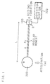
- FIG. 1 is an explanatory view illustrating the detection principle.
- An acceleration sensor of the present invention includes a vibrator 100, a weight section 200 and detection section 300 respectively connected to the vibrator 100.
- the weight section 200 is supported at a support point S, and the position of this support point S is different from the position of the center of gravity G of an assembly of the vibrator 100 and weight section 200.
- an acceleration in one direction the direction of a void arrow in FIG. 1
- an angular moment about the support point S (arrow A, size MLa in FIG.
- This angular moment causes sliding vibration of the vibrator 100 (arrow B in FIG. 1).
- the detection section 300 detects a signal resulting from sliding vibration corresponding to such an angular moment. Since the size of the angular moment is proportional to the size of an acceleration to be detected, it is possible to detect the acceleration by detecting this signal.
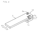
- FIG. 2 is a perspective view showing the structure of an acceleration sensor 10 according to the first embodiment of the present invention
- FIG. 3 is a perspective view of a vibrator 1 of the acceleration sensor 10
- FIG. 4 is a perspective view of a weight section 2 of the acceleration sensor 10.
- the rectangular parallelepiped vibrator 1 length L 1 : 1.3mm, width W 1 : 2.5 mm, thickness T 1 : 0.5 mm
- the rectangular parallelepiped weight section 2 (length L 2 : 5.8 mm, width W 2 : 2.5 mm, thickness T 2 : 0.5 mm, density ⁇ : about 7.5 ⁇ 10 3 kg/m 3 ) made from aluminum.
- electrodes 1a, 1a are formed by longitudinally dividing an electrode into substantially two equal parts are provided on the front face (a face to be bonded to the weight section 2) of the vibrator 1.
- wiring patterns 2a, 2a are provided on the rear face of the weight section 2, at positions facing the electrodes 1a, 1a, in such a manner that the wiring patterns 2a, 2a extend to a region of the front face of the weight section 2.
- the vibrator 1 is connected to a supported end portion of the weight section 2 in such a manner that the electrodes 1a, 1a and the wiring patterns 2a, 2a are bonded to face each other.
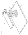
- FIG. 5 is a depiction showing this bonding process.
- the electrodes 1a, 1a and wiring patterns 2a, 2a are bonded together with an adhesive 3 so as to form a conducting path, and, as shown in FIG. 5, the rear face of the vibrator 1 is bonded to a specimen 4 to be detected an acceleration with the adhesive 3 when detecting an acceleration.
- a conductive adhesive is used as the adhesive 3.
- a preferred conductive adhesive is an anisotropic conductive adhesive.
- the anisotropic conductive adhesive has a conducting property only in one direction, and retains an insulating property in other direction. Therefore, this anisotropic conductive adhesive is used for the acceleration sensor 10 of the present invention so that the conductive property is exhibited only in the thickness direction (the vertical direction in FIG. 5). Accordingly, it is possible to prevent a short circuit connection between the divided electrodes 1a, 1a of the vibrator 1 and to ensure and facilitate the electrical connection between the divided electrodes 1a, 1a and the corresponding wiring patterns 2a, 2a, thereby improving the reliability of the electrical connection. Moreover, since the anisotropic conductive adhesive can be uniformly applied onto the divided electrodes 1a, 1a of the vibrator 1, it is possible to improve the readiness of fabrication and the bonding strength.
- FIG. 6 is an illustration showing one example of a detection circuit.
- a differential amplifier 5 whose input terminals are connected to the electrodes 1a, 1a through the wiring patterns 2a, 2a (not shown in FIG. 6).
- the weight section 2 since the weight section 2 also functions as a signal detecting substrate, it is possible to decrease the cost. Moreover, although the electrodes 1a, 1a of the vibrator 1 are hidden by the weight section 2, since the wiring patterns 2a, 2a connected to the electrodes 1a, 1a are extended to the front face of the weight section 2, the detection signals are easily drawn.
- a number of vibrators 1 it is possible to fabricate a number of vibrators 1 at a time. Specifically, after forming a pattern of two lines of electrodes on one piece of piezoelectric single crystal wafer, a plurality of vibrators 1 can be readily cut out from the wafer by, for example, dicing.
- a method of forming the electrode pattern it is possible to use, for example, screen printing, sputtering, plating and etching. As described above, in the first embodiment, the fabrication process is easy and a significant reduction in the cost is achievable.
- the above-mentioned example illustrates a case where a face having the divided electrodes 1a, 1a is located on the front face side (the weight section 2 side).
- the acceleration sensor 10 has the same function and effect and exhibits the same detection characteristics as above.
- an X-cut plate of LiNbO 3 as the piezoelectric single crystal of the vibrator 1.
- the major cause of crosstalk is charge produced by an electromechanical coupling in the thickness direction. Since the X-cut plate of LiNbO 3 has no electromechanical coupling in the thickness direction, if it is used for the acceleration sensor 10 of the present invention which detects an acceleration in the widthwise direction, it is possible to reduce crosstalk significantly and achieve a satisfactory S/N ratio.
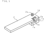
- FIG. 7 is a perspective view showing the structure of an acceleration sensor 10 according to the second embodiment of the present invention
- FIG. 8 is a perspective view of the vibrator 1 of the acceleration sensor 10.
- dividing of the detection portion is ensured by not only the divided electrodes 1a, 1a, but also a groove 1b (depth D: 0.05 mm) formed in the vibrator 1.
- the vibrator 1 of the second embodiment is the same in other configurations and material as that of the first embodiment.
- the weight section 2 is the same as that of the first embodiment.
- the above-mentioned example illustrates a case where the groove 1b is formed in the front face (the weight section 2 side),
- the groove 1b is formed in the opposite side, i.e., the rear face, of course the acceleration sensor 10 has the same function and effect and exhibits the same detection characteristics as above.
- FIG. 9 is a graph showing the relationship between the ratio D/T 1 of the depth D of the groove 1b to the thickness T 1 of the vibrator 1 (the horizontal axis) and the standardized output voltage (logarithmic scale, the vertical axis).
- this output voltage is equivalent to the detection sensitivity. It will be appreciated from the results shown in FIG. 9 that the output voltage increases abruptly until the ratio D/T 1 reaches "0.1", and then gradually rises with an increase of the ratio D/T 1 . Therefore, in order to obtain a sufficient detection sensitivity, it is necessary to provide the groove 1b having a depth D that gives the ratio D/T 1 of not less than 0.1.
- the detection sensitivity From the view point of the detection sensitivity, it is most effective to provide two piezoelectric vibrators side by side. In this case, however, there is a problem that the fabrication cost increases.
- the depth D of the groove 1b as described above to a value not less than 0.1 times the thickness T 1 of the vibrator 1
- the sliding directions in the two detection portions are opposite to each other between both sides of the support point (the center of rotation) of the weight section 2.
- the generated charges and in turn the output voltages have opposite polarities between the both sides of that point.
- FIG. 10 is a graph showing the relationship between the position in a longitudinal direction of the vibrator 1 (the horizontal axis) and the displacement in an excitatory direction of the vibrator 1 (the vertical axis) according to the result of a simulation performed by applying an acceleration in a widthwise direction of the acceleration sensor 10.
- a value "0" in the horizontal axis of FIG. 10 represents the center in the longitudinal direction, and positions in the longitudinal direction are shown by indicating a direction approaching the center of gravity of the weight section 2 as positive.
- the detection portion of the vibrator 1 is divided at a position where the charge distribution is substantially zero, i.e., a position where the angular moment is substantially zero, it is possible to hold a high detection sensitivity and achieve both of a reduction in the cost and an improvement in the sensitivity.
- FIG. 11 is a graph showing the relationship between the ratio W 1 /W 2 of the width W 1 of the vibrator 1 to the width W 2 of the weight section 2 (the horizontal axis) and crosstalk (the vertical direction) according to the result of a simulation performed by applying an acceleration in a thickness direction which is not a direction of an acceleration to be detected by the acceleration sensor 10.
- crosstalk increases as the ratio W 1 /W 2 increases, and particularly, crosstalk shows an abrupt increase when the ratio W 1 /W 2 exceeds "1", i.e., when the width W 1 of the vibrator 1 is larger than the width W 2 of the weight section 2.
- the width W 1 of the vibrator 1 is set less than the width W 2 of the weight section 2 so as to reduce crosstalk and achieve a satisfactory S/N ratio.
- FIG. 12 is a perspective view showing the structure of an acceleration sensor 10 according to the fifth embodiment of the present invention.
- the thickness of the weight section 2 is not uniform, and the thickness (T 2A : 0.5 mm) of a substantially half portion on the vibrator 1 side (the supported-end side) is thinner than the thickness (T 2B : 1.5 mm) of the remaining substantially half portion on the opposite side (the free-end side).
- T 2A 0.5 mm
- T 2B 1.5 mm
- the thickness is increased in both of the directions to the front side and rear side.
- it is possible to increase the thickness in either of the directions to the front side and rear side.
- the above example illustrates the case where the thickness of the free-end side portion of the weight section 2 is made thicker.
- a weight section 2 in which the width of the free-end side portion is larger than that of the supported-end side portion is used, of course a similar effect is obtained.
- the weight section 2 is constructed by using a plurality of materials of different densities so that a portion on the vibrator 1 side (supported-end side portion) is formed from a material with a low density and the opposite portion (free-end side portion) is formed from a material with a high density.
- the supported-end side portion from alumina (the density: about 7.5 ⁇ 10 3 kg/m 3 ) whereby the wiring patterns 2a, 2a are easily formed, and to form the free-end side portion from a material such as molybdenum (the density: about 1.9 ⁇ 10 4 kg/m 3 ), tungsten (the density: about 1.0 ⁇ 10 4 kg/m 3 )or the like which have a high density and are easily molded.
- alumina the density: about 7.5 ⁇ 10 3 kg/m 3
- tungsten the density: about 1.0 ⁇ 10 4 kg/m 3
- FIG. 13 is a perspective view showing the structure of an acceleration sensor 10 according to the first example of the sixth embodiment.
- the weight section 2 of this acceleration sensor 10 is constructed by a first weight 21, which is made from alumina and also functions as a signal detecting substrate like the first and second embodiments, and second weights 22, 22 which are made from molybdenum and attached to the front and rear faces of the free-end side portion of the first weight 21.
- the density ( ⁇ B ) of the free-end side portion is greater than the density ( ⁇ A ) of the supported-end side portion ( ⁇ B > ⁇ A ) and the angular moment of the weight section 2 becomes larger, thereby further improving the detection sensitivity.
- the second weight 22 is attached to each of the front and rear faces of the first weight 21.
- the second weight 22 may be provided only on the front face or rear face.
- the first weight 21 and the second weight 22 have the same width, it is possible to make the width of the second weight 22 larger than that of the first weight 21 so as to further increase the angular moment.
- FIGS. 14A and 14B are the perspective view and cross sectional view of the weight section 2 of an acceleration sensor 10 according to the second example of the sixth embodiment
- FIGS. 15A and 15B are the perspective view and cross sectional view of the weight section 2 of an acceleration sensor 10 according to the third example of the sixth embodiment.
- the second and third examples are constructed so as to make the angular moment of the weight section 2 greater than that of the first example.
- the weight section 2 is constructed by providing the second weight 22 on the front face of the free-end side portion of the first weight 21 in such a manner that the second weight 22 is partly buried in a groove portion 21a of the first weight 21.
- the second weight 22 is provided on only one of the faces of the first weight 21, it may be provided on both the faces.
- the weight section 2 is constructed by fitting the second weight 22 into a hole 21b formed in the free-end side portion of the first weight 21.
- the second example in which the second weight 22 is buried in the first weight 21 and the third example in which the second weight 22 is fitted into the first weight 21 provide excellent resistance to shock and are suitable for use in vehicles having a high possibility to get strong shock.
- FIGS. 16A and 16B are the perspective view and cross sectional view of the weight section 2 of an acceleration sensor 10 according to the fourth example of the sixth embodiment
- FIGS. 17A and 17B are the perspective view and cross sectional view of the weight section 2 of an acceleration sensor 10 according to the fifth example of the sixth embodiment.
- the weight section 2 of each of the fourth and fifth embodiments is constructed by engaging the first weight 21 on the supported-end side with the weight 22 on the free-end side.
- the engaged region has a two-layer structure consisting of the second weight 22 on the front-face side and the first weight 21 on the rear-face side.
- the engaged region has a three-layer structure consisting of the first weight 21 on the front-face side and on the rear-face side, and the second weight 22 in the middle.
- the acceleration sensor 10 is constructed so that the center of gravity of the first weight 21 is located on the vibrator 1, there is no possibility that the weight section 21 hangs down due to its own weight in bonding the first weight 21 to the vibrator 1 with an anisotropic conductive adhesive or the like, thereby facilitating the bonding process.
- the acceleration sensor 10 is constructed so that the center of gravity of the second weight 22 is positioned within the engaged region, there is no possibility that the second weight 22 hangs down due to its own weight in bonding the second weight 22 to the first weight 21 with an adhesive, etc., thereby facilitating the bonding process.
- FIG. 18 is a depiction showing a process of connecting the weight section 2 and vibrator 1 and connecting the vibrator 1 and specimen 4 according to the first example of the seventh embodiment.
- the weight section 2 and vibrator 1, and the vibrator 1 and specimen 4 are electrically connected using bumps 31 of a solder, gold, etc.
- FIG. 19 is a depiction showing a process of connecting the weight section 2 and vibrator 1 and connecting the vibrator 1 and specimen 4 according to the second example of the seventh embodiment.
- the weight section 2 and vibrator 1, and the vibrator 1 and specimen 4 are electrically connected with a cream of solder 32.
- FIG. 20 is a perspective view showing the structure of an acceleration sensor 10 according to the eighth embodiment.
- a FPC (flexible print connector) 33 is used to extend the signal lines from the wiring patterns 2a, 2a of the weight section 2 to a signal detection circuit (not shown).
- the FPC 33 since the signal lines are readily extended, it is possible to reduce the cost significantly.
- FIG. 21 is an illustration showing the connected state of an acceleration sensor 10 and a detection circuit substrate according to the first example of the ninth embodiment.
- the wiring patterns 2a, 2a of the weight section 2 and the detection circuit substrate are connected by wires 34, 34, and the connected portions are coated with a resin 35 such as silicone.
- FIG. 22 is an illustration showing the connected state of an acceleration sensor 10 and a detection circuit substrate according to the second example of the ninth embodiment. Not only the connected portions by wires 34, 34 are coated with the resin 35 like the first example, but also the entire supported portion of the weight section 2 as well as the vibrator 1 is coated with the resin 35 such as silicone.
- such a resin coating is used to prevent accidents such as a disconnection of lines due to strong external shock and to improve the reliability.
- this resin coating is also effective for the cases using ribbon bonding or an FPC.
- FIGS. 23A through 23C are depictions showing a process of fabricating a plurality of the acceleration sensors 10 of the present invention at a time.
- An alumina plate 42 whose front and rear faces are provided with a plurality of wiring patterns 42a that are to be the wiring patterns 2a of the weight section 2 is positioned on a long piezoelectric single crystal element 41 whose front face is provided with a pattern of two lines of electrodes 41a, 41a that are to be the divided electrodes 1a, 1a of the vibrator 1 so that the wiring pattern 42a faces the electrodes 41a, 41a (FIG.
- FIG. 24 is a perspective view showing the structure of an acceleration sensor 10 according to the tenth embodiment of the present invention
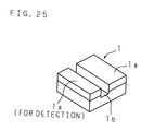
- FIG. 25 is a perspective view of the vibrator 1 of the acceleration sensor 10
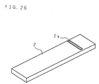
- FIG. 26 is a perspective view of the weight section 2 of the acceleration sensor 10.
- the detection portion of the vibrator 1 is divided by not only the divided electrodes 1a, 1a, but also the groove 1b.
- this divided position is not the center in a longitudinal direction of the vibrator 1 and is slightly off from the center to the free-end side of the weight section 2, and the electrode 1a on the free-end side is shorter in length than the electrode 1a on the supported-end side.
- the function and effect of this groove 1b are the same as those in the second embodiment.
- the wiring patterns 2a, 2a are provided at two positions on the weight section 2, facing the electrodes 1a, 1a of the vibrator 1, respectively, while in the tenth embodiment, the wiring pattern 2a is provided only at a position facing the electrode 1a on the free-end side in such a manner that it extends to a region of the front face of the weight section 2, and thus the wiring pattern 2a is not provided at a position facing the electrode 1a on the supported-end side.
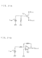
- FIGS. 27A and 27B are illustrations showing one example of a detection circuit according to the tenth embodiment. With the use of an FET 51 and a preamplifier 52, the output voltage of the electrode 1a on the free-end side is amplified and an acceleration is detected.
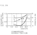
- FIG. 28 is a graph showing the relationship between the divided position (the horizontal axis) and the standardized output voltage and crosstalk (the vertical axis) for each type of detection using the differential output or single output, based on the results of simulations and actual measurements.
- the horizontal axis shows the standardized divided positions with "1" corresponding to the position of the free end of the vibrator 1, "0" the position of the supported end thereof and “0.5” the center in a longitudinal direction of the vibrator 1.
- the solid lines a and b indicate changes in the standardized output voltage in the detection using the differential output and the detection using single output, respectively.
- the broken lines c and d show changes in crosstalk in the detection using the differential output and the detection using single output, respectively.
- ⁇ indicates the actually measured values of the standardized output voltage in the detection using single output.
- the above-described example illustrates the case where the groove 1b is formed in the front face (the weight section 2 side).
- the groove 1b is formed in the opposite side (the rear face)
- the detection characteristics are the same as above.
- the detection portion is divided by only the electrodes 1a, 1a without forming the groove 1b, of course, it is possible to detect an acceleration by a single output from one electrode 1a on the free-end side.
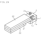
- FIG. 29 is a perspective view showing the structure of an acceleration sensor 10 according to the first example of the eleventh embodiment of the present invention.
- the weight section 2 of the acceleration sensor 10 of the first example is constructed by a first weight 21 made from alumina and second weights 22, 22 made from molybdenum.
- One second weight 22 is mounted on the front face of the first weight 21, which also functions as a signal detecting substrate, so that it extends from the free end to a position slightly overlapping the vibrator 1, while the other second weight 22 is mounted on the rear face of the first weight 21 so that it extends from the free end to a position little before the vibrator 1.
- the second weight 22 on the front face may have a length similar to that of the first weight 21.
- FIG. 30 is a perspective view showing the structure of an acceleration sensor according to the second example of the eleventh embodiment of the present invention.
- the weight section 2 of the acceleration sensor 10 of the second example is constructed by a first weight 21 made from alumina which also functions as a signal detecting substrate and second weights 22, 22 made from molybdenum.
- a portion of the first weight 21 from one end on the vibrator 1 to the center forms a thicker portion 21c thicker than other portion, and one second weight 22 is provided on the front face of the first weight 21 so that it extends from the free end and reaches the thicker portion 21c, while the other second weight 22 is provided on the rear face of the first weight 21 so that it extends from the free end to a position little before the vibrator 1.
- the thicker portion 21c of the first weight 21 may be formed to extend over the entire area of the vibrator 1.
- the thinnest portion of the weight section 2 is positioned on the vibrator 1.
- the thinnest portion of the weight section 2 is located on one end side which is not on the vibrator 1
- resonance occurs at the thinnest portion and strong crosstalk results.
- the eleventh embodiment since the thinnest portion of the weight section 2 is supported and fixed on the vibrator 1, even if an acceleration in a thickness direction is applied, resonance does not occur and crosstalk is little.
- the above-described example illustrates the case where the thinnest portion of the weight section 2 is positioned on the vibrator 1.
- this thinnest portion is not located on the free-end side from the vibrator 1, even if the weight section 2 is further extended from the vibrator 1 to the supported-end side and the extended portion forms the thinnest portion, the same function and effect as those of the above-described examples are obtained.
- FIG. 31 is a perspective view showing the structure of an acceleration sensor 10 according to the twelfth embodiment of the present invention
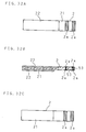
- FIG. 32A, FIG. 32B and FIG. 32C are the front view, cross sectional view and rear view, respectively, of the weight section 2 of the acceleration sensor 10 according to the twelfth embodiment.
- wiring patterns 2a, 2a, 2a, 2a are formed on the front and rear faces at positions corresponding to the electrodes 1a, 1a, and the wiring pattern 2a on the front face are electrically connected with a through-hole 53.
- the wiring patterns 2a, 2a on the rear face and the electrodes la, la are bonded together, so that the output voltages from the electrodes 1a, 1a are drawn through the wiring patterns 2a, 2a on the rear face, the through-hole 53 and the wiring patterns 2a, 2a on the front face.
- the detection portion for sliding vibration of the vibrator 1 is divided into a plurality of parts, a groove 1b is formed, and the inside of this groove 1b is made a hollow state.
- the reason for this is that, if a relatively hard object is placed in this groove 1b, reciprocal sliding vibration of the vibrator 1 to be exerted by an applied acceleration is limited, and the detection performance is lowered.
- the vibrator 1 and weight section 2 are connected with an adhesive such as an anisotropic conductive adhesive so as to form a conducing path. In this case, however, there is a possibility that the adhesive runs into the groove 1b and the groove 1b is filled with the adhesive. Therefore, in order to maintain the inside of the groove 1b in a hollow state, it is necessary to take some measure. The following description will explain specific examples of the measure (the thirteenth to sixteenth embodiments).
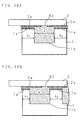
- FIGS. 33A through 33C are cross sectional views showing a process of fabricating an acceleration sensor according to the thirteenth embodiment.
- a material 81 produced by dissolving a powder in a volatile solvent such as alcohol is rubbed into the groove 1b formed in the vibrator 1, with a spatula or squeegee (FIG. 33A).
- a material having a relatively large particle diameter such as Teflon powder and glass micro-balloon.
- a powder layer 82 is formed (FIG. 33B).
- an adhesive 83 such an anisotropic conductive adhesive
- the powder layer 82 is formed on the top side (the weight section 2 side) of the groove 1b, it functions as a cap and prevents the adhesive 83 from running into the groove 1b, thereby maintaining the inside of the groove 1b in a hollow state. Accordingly, the sliding vibration of the vibrator 1 is not limited, and a lowering of the detection performance does not occur.
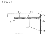
- FIG. 34 is a cross sectional view showing the bonded state of the vibrator and weight section of an acceleration sensor according to the fourteenth embodiment.
- the vibrator 1 and weight section 2 are bonded together with an anisotropic conductive film 84.
- an adhesive can never run into the groove 1b, the inside of the groove 1b is maintained in a hollow state, the sliding vibration of the vibrator 1 is not limited, and a lowering of the detection performance does not occur.
- the anisotropic conductive film 84 is used, it is possible to exhibit conductivity only in a thickness direction and ensure high insulation between the electrodes 1a, 1a.
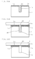
- FIGS. 35A through 35C are cross sectional views showing a process of fabricating an acceleration sensor according to the fifteenth embodiment.
- a dummy structural body 85 is inserted into the groove 1b formed in the vibrator 1 (FIG. 35A).
- the structural body 85 it is possible to use a plate material, various kinds of resist material, wax material and thermoplastic resin, such as Teflon, substantially identical with the groove 1b in shape.
- the vibrator 1 and weight section 2 are bonded together with the adhesive 83 such as an anisotropic conductive adhesive (FIG. 35B). Thereafter, the structural body 85 is removed (FIG. 35C).
- the sliding vibration of the vibrator 1 is not limited, and a lowering of the detection performance does not occur.
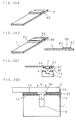
- FIGS. 36A through 36D are perspective views and cross sectional views showing a process of fabricating an acceleration sensor according to the sixteenth embodiment.
- a protruding portion 86 having a width K substantially equal to or larger than a width k of the groove 1b is formed on a face of the weight section 2, to be connected to the vibrator 1, at a position corresponding to the groove 1b (FIG. 36A).
- the protruding portion 86 if it comes into contact with the electrodes 1a, 1a, it is possible to use a structural body made from an insulating material such as ceramics, resins, or the like. If the protruding portion 86 does not come into contact with the electrodes 1a, 1a, a conductive adhesive, metal, etc. may be used.
- the adhesive 83 such as epoxy adhesive and anisotropic conductive adhesive, is applied to both sides of this protruding portion 86 (FIG. 36B).
- the weight section 2 is placed over the vibrator 1 in such a manner that the protruding portion 86 is positioned on the groove 1b (FIG. 36C), and the vibrator 1 and weight section 2 are bonded together (FIG. 36D) so as to electrically connect the electrodes 1a and wiring patterns 2a.
- the protruding portion 86 Since the protruding portion 86 is placed over the top side (the weight section 2 side) of the groove 1b, it functions as a cap, thereby preventing the adhesive 83 from running into the groove 1b and maintaining the inside of the groove 1b in a hollow state. Therefore, sliding vibration of the vibrator 1 is not limited, and a lowering of the detection performance does not occur.
- FIGS. 37A and 37B are perspective views showing other examples of the sixteenth embodiment.
- FIG. 37A shows an example in which a tapered protruding portion 86 is formed
- FIG. 37B illustrates an example in which a rounded protruding portion 86 is formed.
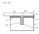
- FIG. 38 is a cross sectional view showing the bonded state of the vibrator and weight section of an acceleration sensor according to the seventeenth embodiment.
- the vibrator 1 and weight section 2 are bonded together with the adhesive 83 such as an anisotropic conductive adhesive in such a manner that the electrodes 1a and wiring patterns 2a are electrically connected, and the groove 1b is filled with a filler 87 such as a silicone resin whose Young's modulus is smaller than that of the adhesive 83.
- the adhesive 83 such as an anisotropic conductive adhesive in such a manner that the electrodes 1a and wiring patterns 2a are electrically connected
- the groove 1b is filled with a filler 87 such as a silicone resin whose Young's modulus is smaller than that of the adhesive 83.
- the sliding vibration is not limited. However, it is not always easy to perform the process of connecting the vibrator 1 and weight section 2 with the adhesive 83 while maintaining this hollow state. Even when the groove 1b is filled with some filler, if the hardness of this filler is low, the sliding vibration is hardly limited. Therefore, the groove 1b is filled with the filler 87 whose Young's modulus is smaller than that of the adhesive 83 connecting the vibrator 1 and weight section 2. In such a case, the occurrence of deterioration of the detection performance can be minimized, and the process of connecting the vibrator 1 and weight section 2 with the adhesive 83 is easily performed because the groove 1b is filled with the filler 87.
- FIGS. 39A and 39B are cross sectional views showing the bonded state of the vibrator and weight section of an acceleration sensor according to the eighteenth embodiment.
- the eighteenth embodiment is an acceleration sensor suitable for use in such an environment subject to strong shock.
- the width k of the groove 1b of the vibrator 1 is made wider than the widths p 1 and p 2 of the respective portions where the electrodes 1a, 1a are formed. Accordingly, since the bonded area between the vibrator 1 and weight section 2 in addition to the bonded area between the electrodes 1a and wiring patterns 2a is significantly increased, it is possible to improve the resistance to shock.
- the position of the groove 1b and the widths of the respective portions may be made symmetrical (FIG. 39A) or asymmetrical (FIG. 39B).
- FIGS. 40A and 40B are plan views of the weight section 2 side of the vibrator 1 and the vibrator 1 side of the weight section 2 of an acceleration sensor according to the nineteenth embodiment.
- An area enclosed by the broken line in FIG. 40B is a region where the vibrator 1 is to be bonded.
- the area of the electrodes 1a of the vibrator 1 and the wiring patterns 2a of the weight section 2 is smaller than the bonded area between the vibrator 1 and weight section 2.
- the area of the electrodes la and wiring patterns 2a is made smaller than the bonded area so as to obtain a sufficient bonding strength in other region. Accordingly, even when the electrodes 1a and wiring patterns 2a do not easily stick to the adhesive, it is possible to increase the bonding strength between the vibrator 1 and weight section 2.
- FIGS. 41A and 41B are plan views of the weight section 2 side of the vibrator 1 of the acceleration sensor according to the nineteenth embodiment
- FIGS. 41C and 41D are plan views of the vibrator 1 side of the weight section 2 of the same.
- the electrodes 1a and wiring patterns 2a are symmetrical about a line, symmetrical about a point and supported at three points.
- the supported-end side portion of the weight section 2 to be bonded to the vibrator 1 is made of a thin or low-dense material. Therefore, there is a problem that the weight portion 2 may be twisted when an acceleration is applied and crosstalk may increase. Besides, since the supported-end side portion is thinner, the bonded area between the free-end side portion and supported-end side portion of the weight section 2 is smaller, causing a problem that the resistance to shock is low.
- the twentieth embodiment was devised to solve such problems.
- FIG. 42A and 42B are the cross sectional view and bottom view showing the structure of an acceleration sensor 10 according to the first example of the twentieth embodiment.
- the weight section 2 of this acceleration sensor 10 is constructed by bonding a first weight 21 on the supported-end side made from alumina to a second weight 22 on the free-end side made from tungsten.
- a cavity 90 is formed on the lower side of the first weight 21 on the supported-end side.
- the depth of this cavity 90 is substantially the same as the depth of the division that divides the detection portion of the vibrator 1, one of the electrodes 1a of the vibrator 1 and the wiring pattern 2a of the weight section 2 formed on the cavity 90 are bonded together, and the upper side of the vibrator 1 is partly stored in the cavity 90.
- the cavity 90 is provided on the supported-end side of the weight section 2 to be bonded to the vibrator 1, even when the supported-end side portion is made thinner, it is reinforced by the wall of the cavity 90. Therefore, even when an acceleration is applied, the weight section 2 is not twisted, thereby enabling a reduction of crosstalk and accurate detection of the acceleration. Moreover, even when the thickness of the portion of the weight section 2 to be bonded to the vibrator 1 is made thinner, since the bonded area between the first weight 21 and second weight 22 of the weight section 2 can be increased, it is possible to improve the resistance to shock. Furthermore, since the free-end side portion of the weight 2 can be made thicker than the supported-end side portion thereof without increasing the height of the acceleration sensor 10, it is possible to improve the detection sensitivity without increasing the size of the structure.
- FIG. 43 is a cross sectional view showing the structure of an acceleration sensor 10 according to the second example of the twentieth embodiment.
- the second example illustrate a case where the second weight 22 on the free-end side is made thicker than the first weight 21 on the supported-end side so as to further increase the angular moment of the weight section 2 compared with the first example and to further improve the detection sensitivity.
- the acceleration sensor device packaging the acceleration sensor 10 therein has such an advantage that it is more easily handled, for example, more easily mounted on a specimen, compared with a unit acceleration sensor.
- an acceleration sensor device of the present invention explained below is arranged so as to efficiently exert sliding vibration of the vibrator 1 due to the angular moment of the weight section 2 and prevent characteristic deterioration even when the acceleration sensor 10 is stored in a package. Moreover, the easiness of the packaging process is one of the important elements for such an acceleration sensor device. In the acceleration sensor device of the present invention explained below, the acceleration sensor is simply packaged.
- wiring patterns are formed on the weight section 2 connected to the vibrator 1, and on a package including a base section and a cap section.
- the weight section 2, or the weight section 2 and vibrator 1 is sandwiched by the package. Furthermore, the sandwiched length of the weight section 2 or vibrator 1 by the package is optimized. Therefore, it is possible to prevent characteristic deterioration of the stored acceleration sensor and to facilitate the packaging process.
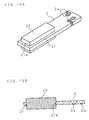
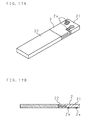
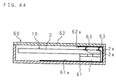
- FIG. 44 is a cross sectional view showing the structure of an acceleration sensor device according to the twenty first embodiment of the present invention.
- the acceleration sensor 10 explained in the first embodiment is stored in a ceramic package 60.
- the package 60 includes a ceramic base section 61 having a cross section substantially in the shape of a square bracket and a ceramic cap section 62 in the shape of a flat plate provided to cover the base section 61.
- the base section 61 and cap section 62 are provided with wiring patterns 61a and 62a, respectively, and the wiring patterns 2a, 2a of the weight section 2 and the wiring pattern 62a of the cap section 62 are connected, for example, with wires 63.
- the output voltages from the electrodes 1a, 1a are drawn to an external differential amplifier (not shown) through the wiring patterns 2a, 2a of the weight section 2, the wiring pattern 62a of the cap section 62 and the wiring pattern 61a of the base section 61.
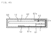
- FIG. 45 is a cross sectional view showing the structure of an acceleration sensor device according to the twenty second embodiment of the present invention.
- the single-output type acceleration sensor 10 explained in the tenth embodiment is stored in the same package 60 as in the twenty first embodiment.
- a preamplifier 52 is stored in the package 60 in such a manner that the preamplifier 52 is installed on the base section 61.
- the wiring pattern 2a of the weight section 2 and the wiring pattern 62a of the cap section 62 are connected, for example, by a wire 63.
- the output voltage from the electrode 1a on the free-end side is input to the preamplifier 52 through the wiring pattern 2a of the weight section 2, the wiring pattern 62a of the cap section 62 and the wiring pattern 61a of the base section 61, and the resulting amplified signal is input to an external signal processing circuit (not shown).
- FIGS. 46A and 46B are the cross sectional view and bottom view of the ceramic base section 61, with a cross section substantially in the shape of a square bracket, of the package 60 of an acceleration sensor device according to the twenty third embodiment of the present invention
- FIGS. 47A and 47B are the cross sectional view and bottom view of the ceramic cap section 62 in the shape of a flat plate of the same package 60.
- a signal detection section 70 provided in the base section 61 is illustrated.
- Electrodes 71, 71 of the signal detection section 70 are connected via through-holes 72, 72 to electrodes 73, 73 for drawing signals out of the package 60, formed on the lower face of the base section 61.
- a wiring pattern 61a formed on the inner face of the base section 61 and an electrode 74 for connection to the ground, formed on the lower face of the base section 61 are connected via a through-hole 75.
- the cap 62 is provided with a wiring pattern 62a which forms a conducting path over the entire top face, and the wiring pattern 62a is bent to cover a certain region on the rear face of the wiring pattern 62a so as to increase the shielding effect. In the example shown in FIGS.
- the base section 61 may be formed in a layered structure, and a signal line and ground line may be arranged between the respective layers.
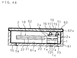
- FIG. 48 is a cross sectional view showing the structure of an acceleration sensor device according to the twenty third embodiment of the present invention.
- an acceleration sensor 10 as explained in the second example of the eleventh embodiment is stored in the package 60 composed of the base section 61 and cap section 62 shown in FIGS. 46A, 46B and FIGS. 47A and 47B, respectively.
- the wiring patterns 2a, 2a of the weight section 2 and the electrodes 71, 71 of the signal detection section 70 are bonded together by connecting members 76, 76 such as thermo-compression ribbon bonding, ultrasonic bonding and FPC.
- An electrode 1c for connection to the ground, formed on the bottom face of the vibrator 1, and the wiring pattern 61a of the base section 61 are bonded together with a conductive adhesive, cream of solder, bump, etc. Further, the wiring pattern 61a of the base section 61 and the wiring pattern 62a of the cap section 62 are connected.
- the acceleration sensor device so that the orientation of the vibrator 1 is opposite to that shown in FIG. 48, i.e., the electrode 74 for connection to the ground and the weight section 2 are connected and the signal detection section 70 and the package 60 are connected. In this case, however, it is necessary to join the vibrator 1 and package 60 so as to exert sliding vibration of the vibrator 1.
- FIG. 49 is a cross sectional view showing the structure of an acceleration sensor device according to the first example of the twenty fourth embodiment of the present invention.
- an acceleration sensor 10 having the characteristics of the second embodiment, the sixth or eleventh embodiment, the tenth embodiment and the twelfth embodiment all together, i.e., an acceleration sensor 10 in which the vibrator 1 is divided by the formation of the groove 1b
- the weight section 2 has a three-layer structure consisting of the first weight 21 and the second weights 22, 22, detection is made based on a single output from only one of the electrodes la, and the wiring patterns 2a, 2a on the front and rear faces are connected with the through-hole 53.
- the first weight 21 is further extended from the top of the vibrator 1, and the extended end portion 21d is sandwiched by the package 60.
- the wiring pattern 2a formed on the upper face of the extended end portion 21d and the wiring pattern 61a for signal detection of the base section 61 of the package 60 are bonded together with a conductive adhesive.
- the package 60 has a structure where the wiring pattern 61a for shielding is formed on the inner front face of the package 60.
- FIG. 50 is a cross sectional view showing the structure of an acceleration sensor device according to the second example of the twenty fourth embodiment of the present invention.
- a metal is used as the material of the cap section 62.
- Other configurations are the same as those of the first example shown in FIG. 49.
- FIGS. 51A and 51B are the plan view and cross sectional view of the weight section 2 of the acceleration sensor device according to the twenty fourth embodiment.
- W 2 and T 2 represent the entire width and entire thickness of the weight section 2, respectively.
- W 21 and T 21 represent the width and thickness of the sandwiched extended end portion 21d, respectively.
- the present inventors found that, in the twenty fourth embodiment in which a part of the weight section 2 is sandwiched by the package 60, the ratio of the size (width W 21 , thickness T 21 ) of the sandwiched extended end portion 21d to the entire size (width W 2 , thickness T 2 ) of the weight section 2 greatly affects the detection characteristics.
- FIG. 52 is a graph showing the relationship between the ratio W 21 /W 2 of the width W 21 of the extended end portion 21d to the entire width W 2 of the weight section 2 (the horizontal axis) and the standardized output voltage (the vertical axis). It will be understood from the result shown in FIG. 52 that as the ratio W 21 /W 2 increases, i.e., as the width W 21 of the sandwiched extended end portion 21d becomes wider, the output voltage is lowered. In particular, when the ratio W 21 /W 2 is not less than 1, since the lowering of the output voltage is noticeable, it is preferable to make the width W 21 of the extended end portion 21d narrower than the entire width W 2 of the weight section 2 so as to prevent the deterioration of the detection characteristics.
- the thickness T 21 of the extended end portion 21d and the entire thickness T 2 of the weight section 2 have a relationship similar to the above-described relationship about the width, and thus it is preferable to make the thickness T 21 of the extended end portion 21d thinner than the entire thickness T 2 of the weight section 2 so as to prevent the deterioration of the detection characteristics.
- the width of the portion sandwiched by the package 60 narrower than the entire width of the weight section 2 and/or making the thickness of the sandwiched portion thinner than the entire thickness of the weight section 2, it is possible to achieve a structure which does not limit the angular moment of the weight section 2, thereby maintaining high detection characteristics.
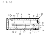
- FIG. 53 is a cross sectional view showing the structure of an acceleration sensor device according to the twenty fifth embodiment of the present invention.
- the acceleration sensor 10 having the characteristics of the second embodiment, the sixth or eleventh embodiment, the tenth embodiment and the twelfth embodiment all together.
- the supported end of the first weight 21 and the supported end of the vibrator 1 are flush with each other, and the supported-end portion of the first weight 21 and the supported-end portion of the vibrator 1 are sandwiched by the package 60.
- the characteristic of the twenty fifth embodiment is that it can achieve a smaller size in comparison with the twenty fourth embodiment.
- L 3 represents the length of the sandwiched portion
- L 1 is the entire length of the vibrator 1.
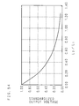
- FIG. 54 is a graph showing the relationship between the ratio L 3 /L 1 of the length L 3 of the sandwiched portion to the entire length L 1 of the vibrator 1 (the horizontal axis) and the standardized output voltage (the vertical axis).
- one of the divided electrodes 1a which is located on the supported-end side and does not participate in the detection of a voltage, and the electrode 1c for connection to the ground formed on the bottom face of the vibrator 1 are made the same electric potential through the wiring pattern 61a of the base section 61. If the output voltage of an acceleration sensor device in which the electrode 1a of the detection portion and the electrode 1c for connection to the ground are not of the same electric potential is "1", the output voltage of the twenty fifth embodiment in which the electrodes 1a and 1c are of the same electric potential is "1.01". Hence, it will be understood that such a structure does not affect the detection characteristics at all. With a structure as illustrated in the twenty fifth embodiment, it is possible to simplify the wiring patterns in the weight section 2 and package 60 and to provide a more simple fabrication process.
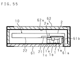
- FIG. 55 is a cross sectional view showing the structure of an acceleration sensor device according to the first example of the twenty sixth embodiment of the present invention.
- an acceleration sensor 10 stored in a package 60 composed of a base section 61 in the shape of a flat plate and a cap section 62 having a cross section in the shape of a square bracket is an acceleration sensor 10 having the characteristics of the fourth example of the sixth embodiment and the tenth embodiment all together, i.e., an acceleration sensor 10 which has a weight section 2 constructed by engaging a first weight 21 on the supported-end side with a second weight 22 on the free-end side and performs single-output type detection using only the output from one of the electrodes 1a.
- the first weight 21 is further extended from the top of the vibrator 1.
- the base section 61 has a protruding portion 61b at a position corresponding to the position of the extended portion.
- the extended portion of the first weight 21 is placed on this protruding portion 61b, and a wiring pattern 2a of the first weight 21 and a wiring pattern 61a formed on the protruding portion 61b are connected.
- the wiring pattern 61a of the protruding portion 61b just needs to be electrically connected, it is possible to use, for example, a silver paste.
- FIG. 56 is a cross sectional view showing the structure of an acceleration sensor device according to the second example of the twenty sixth embodiment of the present invention.
- a metal is used as the material of the cap section 62.
- Other configurations are the same as those of the first example shown in FIG. 55.
- the second example can make the cap section 62 thinner, thereby enabling a reduction in the height of the device.
- a resin cap section 62 is used, it is possible to reduce the cost.
- the height of the protruding portion 61b is formed to a negative tolerance with respect to the thickness of the vibrator 1, it is not necessary to particularly specify the thickness of the vibrator 1 and weight section 2. Besides, it is necessary to simply place the vibrator 1 and weight section 2 sequentially on the base section 61 in the shape of a flat plate and to finally put the cap section 62 thereon, and thus handling of the vibrator 1 and weight section 2 is easier and the fabrication process is simplified.
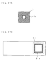
- FIGS. 57A and 57B are plan views of the package 60 side of the vibrator 1 and the vibrator 1 side of the base section 61 of the package 60 of an acceleration sensor device according to the twenty seventh embodiment.
- the twenty seventh embodiment is configured by applying the bonding relationship between the vibrator 1 and the weight section 2 of the above-mentioned nineteenth embodiment to the bonding relationship between the vibrator 1 and the package 60 (the base section 61).
- An area enclosed by the broken line in FIG. 57B is a region where the vibrator 1 is to be bonded.
- the area of the electrode 1c of the vibrator 1 and the wiring pattern 61a of the base section 61 is smaller than the bonded area between the vibrator 1 and the package 60 (the base section 61).
- the area of the electrode 1c and wiring pattern 61a is made smaller than the bonded area so as to obtain a sufficient bonding strength in other region. Accordingly, even when the electrode 1c and wiring pattern 61a do not easily stick to the adhesive, it is possible to increase the bonding strength between the vibrator 1 and the package 60 (the base section 61).
- FIGS. 58A and 58B are plan views of the vibrator 1 side of the base section 61 of the acceleration sensor device according to the twenty seventh embodiment.
- the electrode 1c and wiring pattern 61a in order to increase the degree of adhesion between the vibrator 1 and the package 60 (the base section 61), it is preferable to arrange the electrode 1c and wiring pattern 61a so that they are symmetrical about a line, symmetrical about a point and supported at three points.
- FIG. 59 is a cross sectional view showing the structure of an acceleration sensor device according to the twenty eighth embodiment of the present invention.
- an acceleration sensor 10 Stored in a package 60 having substantially the same structure as that of the above-described twenty sixth embodiment is an acceleration sensor 10 having the characteristic of the above-described twentieth embodiment, i.e., an acceleration sensor 10 in which the supported-end side of the weight section 2 has a cavity structure.
- the wiring pattern 2a of the first weight 21 and the wiring pattern 61a of the base section 61 are connected with a conductive paste 91 made of, for example, a silver paste.
- a conductive paste 91 made of, for example, a silver paste.
- the wiring patterns 2a and 61a may be connected by wire bonding as another method satisfying the conditions for not limiting sliding vibration during the application of an acceleration and the detection signal may be drawn to an external device through the wire bonding.
- the structure of the acceleration sensor stored in the package 60 is only an example and, needless to say, an acceleration sensor having other structure explained by the present invention can be stored in the same manner.
Landscapes
- Physics & Mathematics (AREA)
- General Physics & Mathematics (AREA)
- Pressure Sensors (AREA)
- Gyroscopes (AREA)
Abstract
Description
Since the detection circuit is stored in the package together with an acceleration sensor, it is possible to improve the S/N ratio.
In order to facilitate the electrical connection between the
In other words, the generated charges and in turn the output voltages have opposite polarities between the both sides of that point.
Claims (29)
- An acceleration sensor (10) for detecting an acceleration, characterized by comprising: a vibrator (1) provided with an electrode (1a) and subject to a sliding vibration; and a weight section (2) connected to said vibrator (1) and supported at a position different from a position of a center of gravity of an assembly of said vibrator (1) and weight section (2), and by that said weight section (2) is provided with a wiring pattern (2a) connected to said electrode (1a), said vibrator (1) detects an angular moment about the support point as sliding vibration, which is exerted in said weight section (2) when an acceleration is applied, and an electrical signal corresponding to said acceleration is output from said electrode (1a) through said wiring pattern (2a).
- The acceleration sensor as set forth in claim 1, wherein a detection portion for the sliding vibration of said vibrator (1) is divided by said electrode (1a) which is divided into a plurality of electrode parts.
- The acceleration sensor as set forth in claim 1, wherein a detection portion for the sliding vibration of said vibrator (1) is divided by said electrode (1a) which is divided into a plurality of electrode parts and by a groove (1b) connected to said electrode (1a).
- The acceleration sensor as set forth in claim 3, wherein said vibrator (1) has substantially a rectangular parallelepiped shape, and said groove (1b) has a depth (D) of not less than 10% of a thickness (T1) of said vibrator (1).
- The acceleration sensor as set forth in any one of claims 2 through 4, wherein
a position where said detection section is divided is a position where a charge distribution by said sliding vibration is substantially zero. - The acceleration sensor as set forth in any one of claims 1 through 5, wherein
said vibrator (1) and weight section (2) have substantially a rectangular parallelepiped shape, and a length (W1) of said vibrator (1) in an acceleration detecting direction is not more than a length (W2) of said weight section (2) in the acceleration detecting direction. - The acceleration sensor as set forth in any one of claims 1 through 6, wherein
said weight section (2) has substantially a rectangular parallelepiped shape, and has a greater thickness and/or length in an acceleration detecting direction in its portion on one side opposite to the other side connected to said vibrator (1) than in its portion on the other side. - The acceleration sensor as set forth in any one of claims 1 through 7, wherein
said weight section (2) is composed of a plurality of members (21, 22, 22) of different materials. - The acceleration sensor as set forth in claim 8, wherein
said weight section (2) has a higher density in its portion on one side opposite to the other side connected to said vibrator (1) than in its portion on the other side. - The acceleration sensor as set forth in any one of claims 1 through 9, wherein
said vibrator (1) is bonded to said weight section (2) with an anisotropic conductive adhesive (3). - The acceleration sensor as set forth in any one of claims 2 through 10, wherein
said electrical signal is drawn from one of the divided electrode parts (1a) of said vibrator (1), which is closer to the position of said center of gravity. - The acceleration sensor as set forth in any one of claims 1 through 11, wherein
said weight section (2) has a substantially rectangular parallelepiped shape, and a thinnest portion of said weight section (2) is not located on one side of the position of said vibrator (1), including the position of said center of gravity. - The acceleration sensor as set forth in claim 3 or 4, wherein
said groove (1b) is hollow, and said vibrator (1) and said weight section (2) are connected with an anisotropic conductive film (84). - The acceleration sensor as set forth in claim 3 or 4, wherein
a protruding portion (86) whose width (K) is not less than a width (k) of said groove (1b) is formed at a position on said weight section (2), facing said groove (1b), and said groove (1b) is covered with said protruding portion (86). - The acceleration sensor as set forth in claim 3 or 4, whereinsaid vibrator (1) and said weight section (2) are bonded together with an adhesive (83), and said groove (1b) is filled with a filler (87) whose Young's modulus is smaller than that of said adhesive (83).
- The acceleration sensor as set forth in claim 3 or 4, wherein
said groove (1b) has a width (k) greater than widths (p1, p2) of the divided detection portions of said vibrator (1). - The acceleration sensor as set forth in any one of claims 1 through 16, wherein
said vibrator (1) and said weight section (2) are bonded together with an adhesive (3, 83), and an area of their bonded face is greater than an area of said electrode(1a) and/or said wiring pattern(2a). - The acceleration sensor as set forth in any one of claims 1 through 17, wherein
said weight section (2) has a cavity (90) for storing a part of said vibrator (1). - The acceleration sensor as set forth in any one of claims 1 through 18, wherein
said vibrator (1) is a single crystal piezoelectric element. - The acceleration sensor as set forth in claim 19, whereinsaid single crystal piezoelectric element is an X-cut plate of lithium niobate (LiNbO3).
- An acceleration sensor device, characterized by comprising:an acceleration sensor (10) of any one of claims 1 through 20; anda package (60) including a base (61) provided with a wiring pattern (61a) and a cap (62) covering said base (61), for storing said acceleration sensor (10) therein.
- The acceleration sensor device as set forth in claim 21, wherein
said package (60) has a detection circuit (70) for detecting an acceleration based on said electrical signal. - The acceleration sensor device as set forth in claim 21 or 22, wherein
a part of said weight section (2) is sandwiched by said package (60). - The acceleration sensor device as set forth in claim 21 or 22, wherein
a part of said weight section (2) and a part of said vibrator (1) are sandwiched by said package (60). - The acceleration sensor device as set forth in claim 23 or 24, wherein
the part of said weight section (2) sandwiched by said package (60) is a portion located on one side of the position of said vibrator (1) opposite to the other side including the position of said center of gravity. - The acceleration sensor device as set forth in any one of claims 23 through 25, wherein
a length (L3) of the part of said weight section (2) sandwiched by said package (60) is not more than a length (L1) of said vibrator (1). - The acceleration sensor device as set forth in any one of claims 21 through 26, wherein
said vibrator (1) has a package-side electrode (1c), said package (60) is provided with a wiring pattern (61a) connected to said electrode (1c), said vibrator (1) and package (60) are bonded together with an adhesive, and an area of their bonded face is larger than an area of said electrode (1c) and/or said wiring pattern (61a). - A method of fabricating an acceleration sensor of claim 3 or 4 wherein said groove (1b) is hollow, characterized by comprising the steps of :forming a groove (1b) in said vibrator (1);applying a material (81) produced by dissolving a powder in a volatile solvent to said groove (1b);evaporating said volatile solvent; andconnecting said vibrator (1) and weight section (2) with an adhesive (83).
- A method of fabricating an acceleration sensor of claim 3 or 4 wherein said groove (1b) is hollow, characterized by comprising the steps of:forming a groove (1b) in said vibrator (1);inserting a structural body (85) into said groove (1b);connecting said vibrator (1) and weight section (2) with an adhesive (83); andremoving said structural body (85).
Applications Claiming Priority (6)
| Application Number | Priority Date | Filing Date | Title |
|---|---|---|---|
| JP37581399 | 1999-12-28 | ||
| JP37581399 | 1999-12-28 | ||
| JP2000105426 | 2000-04-06 | ||
| JP2000105426 | 2000-04-06 | ||
| JP2000131714A JP2001349900A (en) | 1999-12-28 | 2000-04-28 | Acceleration sensor and acceleration sensor device |
| JP2000131714 | 2000-04-28 |
Publications (2)
| Publication Number | Publication Date |
|---|---|
| EP1113272A2 true EP1113272A2 (en) | 2001-07-04 |
| EP1113272A3 EP1113272A3 (en) | 2003-10-15 |
Family
ID=27341869
Family Applications (1)
| Application Number | Title | Priority Date | Filing Date |
|---|---|---|---|
| EP00403340A Withdrawn EP1113272A3 (en) | 1999-12-28 | 2000-11-29 | Acceleration sensor, acceleration sensor device, and method of fabricating an acceleration sensor |
Country Status (4)
| Country | Link |
|---|---|
| US (2) | US6578421B1 (en) |
| EP (1) | EP1113272A3 (en) |
| JP (1) | JP2001349900A (en) |
| KR (1) | KR20010082610A (en) |
Cited By (1)
| Publication number | Priority date | Publication date | Assignee | Title |
|---|---|---|---|---|
| US7299695B2 (en) | 2002-02-25 | 2007-11-27 | Fujitsu Media Devices Limited | Acceleration sensor |
Families Citing this family (33)
| Publication number | Priority date | Publication date | Assignee | Title |
|---|---|---|---|---|
| JP2002156386A (en) | 2000-11-17 | 2002-05-31 | Fujitsu Ltd | Acceleration sensor |
| JP2003222636A (en) * | 2002-01-31 | 2003-08-08 | Fujitsu Media Device Kk | Acceleration sensor |
| JP2004037181A (en) * | 2002-07-02 | 2004-02-05 | Hitachi Maxell Ltd | Vibration sensor |
| JP2004077255A (en) * | 2002-08-15 | 2004-03-11 | Fujitsu Media Device Kk | Acceleration sensor |
| JP4342174B2 (en) * | 2002-12-27 | 2009-10-14 | 新光電気工業株式会社 | Electronic device and manufacturing method thereof |
| US7210977B2 (en) | 2003-01-27 | 2007-05-01 | 3M Innovative Properties Comapny | Phosphor based light source component and method of making |
| US7118438B2 (en) * | 2003-01-27 | 2006-10-10 | 3M Innovative Properties Company | Methods of making phosphor based light sources having an interference reflector |
| KR20050103200A (en) * | 2003-01-27 | 2005-10-27 | 쓰리엠 이노베이티브 프로퍼티즈 컴파니 | Phosphor based light source component and method of making |
| US7091661B2 (en) * | 2003-01-27 | 2006-08-15 | 3M Innovative Properties Company | Phosphor based light sources having a reflective polarizer |
| US7091653B2 (en) | 2003-01-27 | 2006-08-15 | 3M Innovative Properties Company | Phosphor based light sources having a non-planar long pass reflector |
| US20040145312A1 (en) * | 2003-01-27 | 2004-07-29 | 3M Innovative Properties Company | Phosphor based light source having a flexible short pass reflector |
| US7312560B2 (en) * | 2003-01-27 | 2007-12-25 | 3M Innovative Properties | Phosphor based light sources having a non-planar long pass reflector and method of making |
| US7245072B2 (en) * | 2003-01-27 | 2007-07-17 | 3M Innovative Properties Company | Phosphor based light sources having a polymeric long pass reflector |
| US20040159900A1 (en) * | 2003-01-27 | 2004-08-19 | 3M Innovative Properties Company | Phosphor based light sources having front illumination |
| JP2007285977A (en) * | 2006-04-19 | 2007-11-01 | Fujitsu Media Device Kk | Angular velocity sensor |
| JP4850572B2 (en) * | 2006-04-19 | 2012-01-11 | 富士通株式会社 | Angular velocity sensor |
| US20080072677A1 (en) * | 2006-09-26 | 2008-03-27 | Sorah Rhee | Bending mode accelerometer |
| US20090253359A1 (en) * | 2007-12-28 | 2009-10-08 | Arlen Morgan Smith | Tent chimney and mounted stove |
| KR101158044B1 (en) * | 2008-12-03 | 2012-06-22 | 한국전자통신연구원 | The high sensitivity Z-axis vibration detection sensor and Method for fabricating thereof |
| US8263426B2 (en) | 2008-12-03 | 2012-09-11 | Electronics And Telecommunications Research Institute | High-sensitivity z-axis vibration sensor and method of fabricating the same |
| US8225252B2 (en) * | 2010-06-25 | 2012-07-17 | Intel Corporation | Systems, methods, apparatus and computer readable mediums for use in association with systems having interference |
| JP5862567B2 (en) * | 2010-08-24 | 2016-02-16 | 日本電気株式会社 | Vibration sensor |
| DE102011011160B4 (en) * | 2011-01-05 | 2024-01-11 | Robert Bosch Gmbh | Micromechanical component and manufacturing process for a micromechanical component |
| JP5936374B2 (en) | 2011-02-15 | 2016-06-22 | キヤノン株式会社 | Piezoelectric vibration type force sensor, robot hand and robot arm |
| US9187974B2 (en) | 2012-04-27 | 2015-11-17 | Cameron International Corporation | System and method for position monitoring using ultrasonic sensor |
| US9804039B2 (en) | 2012-04-27 | 2017-10-31 | Cameron International Corporation | System and method for position monitoring using ultrasonic sensor |
| US9163471B2 (en) * | 2012-04-27 | 2015-10-20 | Cameron International Corporation | Position monitoring system and method |
| US9525119B2 (en) * | 2013-12-11 | 2016-12-20 | Fujifilm Dimatix, Inc. | Flexible micromachined transducer device and method for fabricating same |
| JP6508326B2 (en) * | 2015-03-12 | 2019-05-08 | 株式会社村田製作所 | Acceleration detection device and method of manufacturing the same |
| US10060943B2 (en) * | 2016-03-18 | 2018-08-28 | Rosemount Aerospace Inc. | Symmetric MEMS piezoelectric accelerometer for lateral noise |
| US10054607B2 (en) | 2016-05-12 | 2018-08-21 | Google Llc | Using accelerometer to self-test piezoelectric component in a portable device |
| EP4220190A3 (en) * | 2020-11-02 | 2023-11-01 | Kistler Holding AG | Acceleration sensor |
| CN116481970A (en) * | 2023-04-14 | 2023-07-25 | 南京航空航天大学 | An experimental platform and experimental method for dynamic adhesion performance testing |
Family Cites Families (10)
| Publication number | Priority date | Publication date | Assignee | Title |
|---|---|---|---|---|
| DE69211269T2 (en) * | 1991-09-24 | 1997-01-23 | Murata Manufacturing Co | Accelerometer |
| JP2780594B2 (en) | 1993-03-19 | 1998-07-30 | 株式会社村田製作所 | Acceleration sensor |
| JPH07209071A (en) | 1994-01-21 | 1995-08-11 | Fujikura Ltd | Piezoelectric vibration sensor |
| JP3373032B2 (en) * | 1994-03-15 | 2003-02-04 | 富士通株式会社 | Acceleration sensor |
| DE4428124B4 (en) * | 1994-08-09 | 2005-08-18 | Robert Bosch Gmbh | accelerometer |
| JPH09318650A (en) | 1996-05-27 | 1997-12-12 | Matsushita Electric Works Ltd | Sensor device and its manufacture |
| JPH10206456A (en) | 1997-01-21 | 1998-08-07 | Matsushita Electric Ind Co Ltd | Acceleration sensor and method of manufacturing the same |
| JPH11211748A (en) | 1998-01-20 | 1999-08-06 | Matsushita Electric Ind Co Ltd | Electromechanical transducer, method of manufacturing the same, and acceleration sensor |
| JP3346261B2 (en) | 1998-02-13 | 2002-11-18 | 株式会社村田製作所 | Piezoelectric sensor |
| JP2000097707A (en) | 1998-09-18 | 2000-04-07 | Fujitsu Ltd | Acceleration sensor |
-
2000
- 2000-04-28 JP JP2000131714A patent/JP2001349900A/en not_active Withdrawn
- 2000-11-28 US US09/722,716 patent/US6578421B1/en not_active Expired - Fee Related
- 2000-11-29 EP EP00403340A patent/EP1113272A3/en not_active Withdrawn
- 2000-12-28 KR KR1020000083450A patent/KR20010082610A/en not_active Ceased
-
2003
- 2003-04-04 US US10/406,252 patent/US6792806B2/en not_active Expired - Fee Related
Cited By (1)
| Publication number | Priority date | Publication date | Assignee | Title |
|---|---|---|---|---|
| US7299695B2 (en) | 2002-02-25 | 2007-11-27 | Fujitsu Media Devices Limited | Acceleration sensor |
Also Published As
| Publication number | Publication date |
|---|---|
| JP2001349900A (en) | 2001-12-21 |
| US6578421B1 (en) | 2003-06-17 |
| KR20010082610A (en) | 2001-08-30 |
| US6792806B2 (en) | 2004-09-21 |
| US20030200805A1 (en) | 2003-10-30 |
| EP1113272A3 (en) | 2003-10-15 |
Similar Documents
| Publication | Publication Date | Title |
|---|---|---|
| US6578421B1 (en) | Acceleration sensor, acceleration sensor device, and method of fabricating an acceleration sensor | |
| JP5919310B2 (en) | Method for manufacturing microelectromechanical element, microelectromechanical element and use thereof | |
| JP5487672B2 (en) | Physical quantity sensor | |
| US5652384A (en) | Sensor structure with L-shaped spring legs | |
| JP4701505B2 (en) | Inertial transducer | |
| CN102680737B (en) | Acceleration detector or device, inclination sensor or detection device, electronic equipment | |
| US7024947B2 (en) | Detection device including circuit component | |
| JPWO1999060413A1 (en) | Acceleration sensor and acceleration device using this acceleration sensor | |
| KR20010013748A (en) | Acceleration sensor and acceleration apparatus using acceleration sensor | |
| JPH05215766A (en) | Inspectable acceleration sensor | |
| KR20060069239A (en) | Acceleration sensor | |
| CN108291796A (en) | Piezoelectric transflexural sensor and detection device | |
| CN114485599B (en) | Physical quantity sensors, physical quantity sensor devices and inertial measurement devices | |
| JP2001349732A (en) | Micromachine device and angular acceleration sensor and acceleration sensor | |
| US6823735B2 (en) | Acceleration sensor | |
| JP4822769B2 (en) | Acceleration sensor | |
| WO2021095658A1 (en) | Sensor device and sensor | |
| CN100565848C (en) | Electronic component manufacturing method and electronic component | |
| JP2009068936A (en) | Physical quantity detecting apparatus | |
| US10191078B2 (en) | Acceleration sensor | |
| US20080257045A1 (en) | Sensor device for detecting physical quantity | |
| EP1895269A2 (en) | Vibration sensor | |
| JP2010130455A (en) | Piezoelectric oscillator | |
| JP2005315847A (en) | Acceleration sensor | |
| WO2023079896A1 (en) | Acceleration detection device |
Legal Events
| Date | Code | Title | Description |
|---|---|---|---|
| PUAI | Public reference made under article 153(3) epc to a published international application that has entered the european phase |
Free format text: ORIGINAL CODE: 0009012 |
|
| AK | Designated contracting states |
Kind code of ref document: A2 Designated state(s): AT BE CH CY DE DK ES FI FR GB GR IE IT LI LU MC NL PT SE TR |
|
| AX | Request for extension of the european patent |
Free format text: AL;LT;LV;MK;RO;SI |
|
| PUAL | Search report despatched |
Free format text: ORIGINAL CODE: 0009013 |
|
| AK | Designated contracting states |
Kind code of ref document: A3 Designated state(s): AT BE CH CY DE DK ES FI FR GB GR IE IT LI LU MC NL PT SE TR |
|
| AX | Request for extension of the european patent |
Extension state: AL LT LV MK RO SI |
|
| 17P | Request for examination filed |
Effective date: 20031025 |
|
| 17Q | First examination report despatched |
Effective date: 20040513 |
|
| AKX | Designation fees paid |
Designated state(s): DE FR |
|
| STAA | Information on the status of an ep patent application or granted ep patent |
Free format text: STATUS: THE APPLICATION IS DEEMED TO BE WITHDRAWN |
|
| 18D | Application deemed to be withdrawn |
Effective date: 20100601 |