EP1112844B1 - Sheet-like object feed unit in sheet-fed rotary printing press - Google Patents
Sheet-like object feed unit in sheet-fed rotary printing press Download PDFInfo
- Publication number
- EP1112844B1 EP1112844B1 EP00128373A EP00128373A EP1112844B1 EP 1112844 B1 EP1112844 B1 EP 1112844B1 EP 00128373 A EP00128373 A EP 00128373A EP 00128373 A EP00128373 A EP 00128373A EP 1112844 B1 EP1112844 B1 EP 1112844B1
- Authority
- EP
- European Patent Office
- Prior art keywords
- sheet
- gripper
- unit
- holding
- improper
- Prior art date
- Legal status (The legal status is an assumption and is not a legal conclusion. Google has not performed a legal analysis and makes no representation as to the accuracy of the status listed.)
- Expired - Lifetime
Links
Images


Classifications
-
- B—PERFORMING OPERATIONS; TRANSPORTING
- B65—CONVEYING; PACKING; STORING; HANDLING THIN OR FILAMENTARY MATERIAL
- B65H—HANDLING THIN OR FILAMENTARY MATERIAL, e.g. SHEETS, WEBS, CABLES
- B65H7/00—Controlling article feeding, separating, pile-advancing, or associated apparatus, to take account of incorrect feeding, absence of articles, or presence of faulty articles
- B65H7/02—Controlling article feeding, separating, pile-advancing, or associated apparatus, to take account of incorrect feeding, absence of articles, or presence of faulty articles by feelers or detectors
-
- B—PERFORMING OPERATIONS; TRANSPORTING
- B41—PRINTING; LINING MACHINES; TYPEWRITERS; STAMPS
- B41F—PRINTING MACHINES OR PRESSES
- B41F21/00—Devices for conveying sheets through printing apparatus or machines
- B41F21/04—Grippers
- B41F21/05—In-feed grippers
-
- B—PERFORMING OPERATIONS; TRANSPORTING
- B41—PRINTING; LINING MACHINES; TYPEWRITERS; STAMPS
- B41F—PRINTING MACHINES OR PRESSES
- B41F33/00—Indicating, counting, warning, control or safety devices
- B41F33/04—Tripping devices or stop-motions
- B41F33/06—Tripping devices or stop-motions for starting or stopping operation of sheet or web feed
-
- B—PERFORMING OPERATIONS; TRANSPORTING
- B41—PRINTING; LINING MACHINES; TYPEWRITERS; STAMPS
- B41F—PRINTING MACHINES OR PRESSES
- B41F33/00—Indicating, counting, warning, control or safety devices
- B41F33/04—Tripping devices or stop-motions
- B41F33/14—Automatic control of tripping devices by feelers, photoelectric devices, pneumatic devices, or other detectors
Definitions
- the present invention relates to a sheet-like object feed unit in a sheet-fed rotary printing press, which prevents a sheet-like object from being fed to a printing unit in an abnormal state.
- a sheet fed out from a feed unit is conveyed on a feeder board and feedboard, and is jogged in the circumferential direction by the front lay of a registration unit provided at the distal end of the feedboard.
- the sheet jogged in the circumferential direction is gripped by the gripper of a swing arm shaft pregripper, and is supplied to the impression cylinder of a printing unit through gripping change from the gripper of the swing arm shaft pregripper to the gripper of the impression cylinder.
- An improper paper feeding detecting means for detecting that a conveyed sheet moves over the front lay or two sheets are fed in an overlaying state, i.e., abnormal or defective paper feeding, is provided at the distal end of the feedboard. When the improper paper feeding detecting means detects improper paper feeding, impression throw-off is performed, and printing is stopped.
- an improper paper feeding detector for detecting whether improper paper feeding has occurred and generating a corresponding signal is provided to a registration unit. If the improper paper feeding detector does not detect improper paper feeding, printing is continued in the impression throw-on state. If the improper paper feeding detector detects improper paper feeding, the printing cylinders of all the printing units are disengaged and the printing operation is stopped. At this time, paper conveyance is stopped by a front lay, and the sheets are left in the registration unit so as not be supplied to the printing units.
- US-Patent 1,740,058 shows a sheet-like object feed unit in a sheet-fed rotary printing press according to the preamble of claim 1 of the present invention and is directed to means for automatically causing the impression cylinder of a rotary printing press to retain the sheet thereon beyond its point of delivery, upon a failure of the sheet feeder to feed a succeeding sheet and causing the sheet on the impression cylinder to receive a second impression as it is carried through the press and thereby protects the impression cylinder packing from receiving said last named impression.
- a sheet-like object feed unit in a sheet-fed rotary printing press comprising a convey unit for conveying a sheet-like object, improper feeding detecting means, disposed on a sheet-like object convey path including the convey unit, for detecting improper feeding of the sheet-like object, a first holding unit disposed downstream of the convey unit in a sheet-like object convey direction and having first holding means for holding the sheet-like object conveyed by the convey unit, a second holding unit disposed downstream of the first holding unit in the sheet-like object convey direction and having second holding means for holding the sheet-like object held by the first holding unit, and first disable means for disabling the second holding means when the improper feeding detecting means detects improper feeding of the sheet-like object, wherein the improper feeding detecting means is disposed downstream of said convey unit in the sheet-like object convey direction.
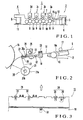
- Fig. 1 shows the overall arrangement of a sheet-fed rotary printing press according to an embodiment of the present invention.
- a sheet-fed rotary printing press 1 has a feed unit 2 with a pile board 6 on which sheets 5 are stacked, a plurality of printing units 3a to 3d subordinately arranged to perform printing, in four colors, on the sheets 5 fed from the feed unit 2, and a delivery unit 4 for delivering the sheets 5 conveyed from the fourth-color printing unit 3d.
- Each of the printing units 3a to 3d has a plate cylinder 7 with a plate mounted on its circumferential surface, an inker and dampener (not shown) for supplying ink and dampening water to the surface of the plate, a blanket cylinder 8 in contact with the plate cylinder 7, and an impression cylinder 9 in contact with the blanket cylinder 8.
- Transfer cylinders 10 disposed among the respective impression cylinders 9 of the printing units 3a to 3d to be in contact with them.
- the delivery unit 4 has a delivery chain (not shown) for conveying the sheets 5 printed by the fourth-color printing unit 3d, and a pile board 11 on which the sheets 5 delivered as they are conveyed by the delivery chain are stacked.
- a feeder board 12, feedboard 13, swing arm shaft pregripper 14, and transfer cylinder 15 are disposed between the feed unit 2 and the first-color printing unit 3a.
- the feeder board 12 and feedboard 13 will be described in detail with reference to Figs. 2 and 3 .
- a plurality of paper feed belts 16a are applied parallel to each other along the feeder board 12 which is inclined in contact with a belt roller 16.
- the paper feed belts 16a cooperate with a pressure roller 17 to convey the sheets 5 on the feeder board 12.
- the elongated plate-like feedboard 13 is arranged in front of the feeder board 12 in the paper convey direction and is supported through a connecting plate 18 at the same angle of inclination as that of the feeder board 12.
- a support plate 19 extends between a pair of opposing frames 20 (see Fig. 5 ) to support the connecting plate 18 and feedboard 13.
- the swing arm shaft pregripper 14 is comprised of a swing arm shaft 21 in which the axes of an outer surface 21a and eccentric shaft 21b supported by bearings are eccentric, an arm 22 pivotal together with the swing arm shaft 21, and a swing arm gripper 23 supported at the distal end of the arm 22.
- the swing arm shaft pregripper 14 is so-called a lower swing in which the swing arm shaft 21 is arranged below the feedboard 13 serving as the convey path for the sheets 5, and the swing arm gripper is provided at the distal end of the swing arm shaft pregripper 14.
- the swing arm shaft pregripper 14 grips, with its swing arm gripper 23, a sheet 5 stopped by the front lay (not shown) at the distal end of the feedboard 13, and conveys it as the arm 22 pivots, so that gripping change is performed with a gripper 43 (to be described later; see Fig. 4 ) of the transfer cylinder 15.
- the front lay is an arrangement known to the person skilled in the art, as is disclosed in Japanese Patent Laid-Open No. 57-182443 .
- the contents of Japanese Patent Laid-Open No. 57-182443 are incorporated in this specification.
- an overreaching detector 28, a double-sheet detector 29, a pair of sheet skew detectors 30 and 31, and an impression throw-in detector 32 are attached to the feedboard 13.
- the detectors 28 to 32 are comprised of pairs of opposing light-emitting and light-receiving elements to constitute an improper paper feeding detector 24.
- Fig. 3 shows the light-receiving elements of the detectors 28 to 32, and the paper convey direction with an arrow.
- a holder 26 is fixed by split clamping to a support shaft 25 extending between the pair of frames 20.
- Light-receiving elements 27 of the detectors 28 to 32 are mounted on the holder 26 through a bracket 26a substantially in a row such that their light-receiving surfaces face down.
- the light-emitting element of the overreaching detector 28 is fixed to the lower surface of the feedboard 13 with a bolt with its light-emitting surface facing up to oppose the corresponding light-receiving element.
- the overreaching detector 28 detects this and outputs an abnormal signal.
- the light-emitting element of the double-sheet detector 29 is fixed to the lower surface of the feedboard 13, disposed slightly upstream of the front lay in the paper convey direction, with a bolt with its light-emitting surface facing up to oppose the corresponding light-emitting element. While the sheets 5 should be conveyed onto the feedboard 13 one by one, if two sheets are fed in an overlaying state, the double-sheet detector 29 detects a change in light transmittance due to the sheets 5 and outputs an abnormal signal.
- the light-transmitting elements of the sheet skew detectors 30 and 31 are fixed to the lower surface of the feedboard 13 with bolts with their light-transmitting surfaces facing up to oppose the corresponding light-receiving elements.
- the sheet skew detectors 30 and 31 detect this on the basis of the combinations of the outputs of the two light-receiving elements, and output an abnormal signal.
- the impression throw-in detector 32 for detecting the impression throw-in timing when the sheet 5 passes above it is fixed to the front end of the connecting plate 18 in the paper convey direction.
- a side lay unit 33 which causes the end of the sheet 5 under conveyance to abut against the gauge and registers the sheet 5 in the right-to-left direction is attached to the end of the connecting plate 18 in a direction perpendicular to the paper convey direction.
- a pivotal swing arm gripper opening/closing cam 35 is supported by the swing arm shaft 21.
- the swing arm gripper opening/closing cam 35 is swung by an air cylinder 61a ( Fig. 8 ) between the position of the solid line and that of the alternate long and two short dashed line in Fig. 4 .
- a cam member 36 is fixed to the swing arm gripper opening/closing cam 35.
- the cam member 36 has, on its circumferential surface, a high cam surface 36a at its center and low cam surfaces 36b and 36c at its two ends.
- the arm 22 pivotally supports a gripper shaft 37.
- the proximal end of the swing arm gripper 23 is axially mounted on the gripper shaft 37 so the swing arm gripper 23 pivots together with the gripper shaft 37.
- One end of a swing arm gripper opening/closing roller 38 is fixed to the other end of a lever (not shown) axially mounted to the gripper shaft 37, and is biased to abut against the cam surface of the cam member 36.
- the swing arm gripper opening/closing cam 35 is pivoted by the air cylinder 61a ( Fig. 8 ) counterclockwise in Fig. 4 about the swing arm shaft 21 as the pivot center, and is positioned at the position indicated by the alternate long and two short dashed line. Therefore, even when the swing arm gripper 23 is located at the distal end of the feedboard 13, since the swing arm gripper opening/closing roller 38 abuts against the other low cam surface 36c to open the swing arm gripper 23, the swing arm gripper 23 will not grip the sheet 5 stopped by the front lay (not shown) at the distal end of the feedboard 13.
- the improperly fed sheet 5 is not supplied from the transfer cylinder 15 to the respective printing units 3 located on the downstream side, so the surfaces of the blanket cylinders 8, impression cylinder 9, and transfer cylinder .10 of the respective printing units 3a to 3d will not be damaged.
- the swing arm gripper opening/closing cam 35, swing arm gripper opening/closing roller 38, and air cylinder 61a constitute the second disable means of the swing arm gripper 23.
- a circular disk-shaped gripper opening/closing cam 41 is fixed to the frame 20.
- the gripper opening/closing cam 41 has, on its circumferential surface, a high cam surface 41a and two low cam surfaces 41b and 41c which are formed apart from each other at an angular interval of about 180° in the circumferential direction.
- a bearer 40 of the transfer cylinder 15 pivotally supports a gripper shaft 42.
- the proximal end of a gripper 43 is axially mounted to the gripper shaft 42, so the gripper 43 pivots together with the gripper shaft 42.
- a lever 44 The central portion of a lever 44 is axially mounted to the gripper shaft 42.
- a gripper opening/closing roller 45 is fixed to one end of the lever 44, and a non-motion roller 47 serving as a gripping change regulating member is fixed to the other end of the lever 44 through a bracket 46.
- a torsion bar 48 is axially mounted to one end of the gripper shaft 42.
- a pivot moment in the counterclockwise direction in Fig. 4 is constantly applied to the gripper shaft 42 by the torsional moment of the torsion bar 48.
- the gripper opening/closing roller 45 is pressed against the circumferential surface of the gripper opening/closing cam 41.
- the gripper opening/closing roller 45 abuts against the high cam surface 41a, and accordingly the gripper shaft 42 pivots counterclockwise in Fig. 4 to close the gripper 43.
- the gripper 43 is opened and closed in this manner, it performs sheet gripping change with the swing arm gripper 23.
- the transfer cylinder 15 further rotates and the gripper opening/closing roller 45 abuts against the low cam surface 41c, the gripper 43 is opened so the sheet 5 gripped by it is transferred to the gripper (not shown) of the impression cylinder 9 through gripping change.
- a support member 52 fixed to the frames 20 has a recess 53 extending from its lower surface to its side surface, and a through hole 54 extending perpendicularly to the recess 53.
- a shaft 55 extends through the support member 52 and is rotatably supported by the frame 20.
- a cover 56 rotatable about the shaft 55 as the rotation center so as to open/close, is attached to the shaft 55.
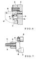
- An arched gripper closing cam 57 serving as a cam member has one end engaged in the recess 53 of the support member 52, as shown in Fig. 6 .
- the gripper closing cam 57 is supported to be pivotal about a pin 58, inserted in a through hole 57a formed on its end engaged in the recess 53 and in the through hole 54 of the support member 52, as the pivot center.
- One end of a lever 60 is fixed to the other end of the gripper closing cam 57, and the other end of the lever 60 is pivotally mounted to a rod 62 of an air cylinder 61b fixed to the frame 20.
- the rod 62 of the air cylinder 61b is kept retracted, and the gripper closing cam 57 is kept retreated from the non-motion roller 47, i.e., is located at the position indicated by the solid line in Fig. 4 .
- the gripper closing cam 57 slightly pivots clockwise in Fig. 4 about the pin 58 as the pivot center, and is positioned at the position indicated by the alternate long and two short dashed line, so that it abuts against the non-motion roller 47, thereby forcibly closing the gripper 43.
- the non-motion roller 47, gripper closing cam 57, and air cylinder 61b constitute the first disable means of the gripper 43.
- a support plate 67 is fixed to the base plate 65, fixed to the frames 20, through a stud 66.
- a paper guide 68 fixed to the support plate 67 through metal fixtures 69 has a curved section, and extends in the axial direction of the transfer cylinder 15 to be close to its circumferential surface.
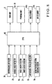
- Fig. 8 shows functional blocks of the sheet-fed rotary printing press described above.
- the detection signals from the detectors 28 to 32 constituting the improper paper feeding detector 24 are output to a CPU (Central Processing Unit) 80.
- the CPU 80 controls the feed unit 2, printing units 3a to 3d, and air cylinders 61a and 61b on the basis of the detection signals from the detectors 28 to 32, and performs paper feed operation including a countermeasure for improper paper feeding.
- the CPU 80 drives the feed unit 2, so the sheet 5 is conveyed onto the connecting plate 18 by the paper feed belts 16a through the feeder board 12 (step S0). At this time, when the leading end of the sheet 5 is detected by the impression throw-in detector 32, the CPU 80 outputs a cylinder engagement instruction to the respective printing units 3a to 3d (step S1).
- the sheet 5 is further conveyed from the connecting plate 18 onto the feedboard 13, and is stopped by the front lay as the conveyance is regulated. If the sheet 5 is properly fed, none of the detectors 28 to 31 constituting the improper paper feeding detector 24 outputs an abnormal signal in steps S2 to S4. The sheet 5 is thus fed to the transfer cylinder 15 by the swing arm shaft pregripper 14, and printing operation is started.
- step S2 If improper paper feeding occurs at the start of printing or during printing, at least one of the detectors 28 to 31 constituting the improper paper feeding detector 24 detects improper paper feeding, and outputs an abnormal signal (steps S2 to S4).
- the CPU 80 stops the sheets 5 (step S5), and drives the air cylinder 61a to open the swing arm gripper 23 (step S6). Subsequently, the CPU 80 drives the air cylinder 61b to close the gripper 43 (step S7).
- the CPU 80 performs impression throw-off of the printing units 3a to 3d to stop printing operation (step S8).
- the gripping operation of the swing arm gripper 23 to grip the sheet 5 stopped at the front lay is regulated, and simultaneously gripping change by the gripper 43 of the transfer cylinder 15 is regulated.
- the swing arm gripper opening/closing cam 35 pivots counterclockwise in Fig. 4 about the swing arm shaft 21 as the pivot center, and is positioned at the position indicated by the alternate long and two short dashed line.
- a stopping means for stopping gripping change of the gripper 43 is constituted by the non-motion roller 47, gripper closing cam 57 for setting the non-motion roller 47 in the non-motion state, and air cylinder 61b for actuating the gripper closing cam 57.
- the number of components is thus minimized to simplify the structure, and gripping change of the gripper 43 is regulated reliably.
- the swing arm shaft pregripper 14 since the swing arm shaft pregripper 14 is the lower swing, even if the improperly fed sheet 5 is not gripped by the swing arm gripper 23, it may sometimes be erroneously guided by the swing arm gripper 23 of the swing arm shaft pregripper 14 to slide on the swing arm gripper 23 and be conveyed to the transfer cylinder 15. Even in this case, the improper paper feeding detector 24 detects improper paper feeding.
- the air cylinder 61b is thus driven and the gripper closing cam 57 is positioned at the position indicated by the alternate long and two short dashed line in Fig. 4 , where it is in contact with the non-motion roller 47.
- the gripper opening/closing roller 45 opposes the low cam surface 41b of the gripper opening/closing cam 41, the gripper shaft 42 will not pivot.
- the improperly fed sheet 5 erroneously conveyed to the transfer cylinder 15 will not be gripped by the gripper 43. Accordingly, the improperly fed sheet 5 is not conveyed to the respective printing units 3a to 3d located downstream of the transfer cylinder 15 in the paper convey direction, and is not delivered to the delivery unit 4. As a result, the surfaces of the plate cylinders 7, blanket cylinders 8, impression cylinders 9, and transfer cylinders 10 of the respective printing units 3 will not be damaged by the improperly fed sheet 5. Since the improperly fed sheet 5 is not conveyed downstream of the transfer cylinder 15 in the paper convey direction but stays on the feedboard 13, it can be removed easily.
- the CPU 80 sets the air cylinder 61b in the non-motion state to retract the rod 62, and retracts the gripper closing cam 57, through the lever 60, to a retreat position indicated by the solid line in Fig. 4 , where it is retreated from the non-motion roller 47.
- the home position return checking sensor 70 recognizes that the gripper closing cam 57 has moved to this position, and then printing is started, so the gripper 43 does not fail to grip. Therefore, the surfaces of the plate cylinders 7, blanket cylinders 8, impression cylinders 9, and transfer cylinders 10 will not be damaged by the sheet 5 that has failed to be gripped.
- the swing arm shaft pregripper 14 is used as the first holding unit.
- the first holding unit may be the transfer cylinder 15.
- the transfer cylinder 15 is used as the second holding unit, the second holding unit may be the impression cylinder 9. It suffices if the holding unit is a sheet-like object holding unit with a sheet-like object holding means for transferring a sheet-like object.
- the sheet-like object is a paper sheet.
- the sheet-like object may be a film made of, e.g., polyvinyl chloride.
- the swing arm gripper 23 Upon detection by the improper paper feeding detector 24, only the swing arm gripper 23 is opened and the gripper 43 is closed. Alternatively, the impression throw-on instruction may be canceled simultaneously, and all the cylinders may be set in the impression throw-off state.
- the air cylinder 61b may be set in the opposite direction, and when the rod 62 is retracted, the gripper closing cam 57 may set the non-motion roller 47 in the non-motion state.
- a motor rotatable in the forward/reverse direction may be used in place of the air cylinder 61b, a screw rod may be provided as the rotation shaft of the motor, and a threaded portion threadably engageable with this screw rod may be formed on the lever 60.
- the structure is simplified, and gripping change is regulated reliably.
Abstract
Description
- The present invention relates to a sheet-like object feed unit in a sheet-fed rotary printing press, which prevents a sheet-like object from being fed to a printing unit in an abnormal state.
- Conventionally, in a sheet-fed rotary printing press, a sheet fed out from a feed unit is conveyed on a feeder board and feedboard, and is jogged in the circumferential direction by the front lay of a registration unit provided at the distal end of the feedboard. The sheet jogged in the circumferential direction is gripped by the gripper of a swing arm shaft pregripper, and is supplied to the impression cylinder of a printing unit through gripping change from the gripper of the swing arm shaft pregripper to the gripper of the impression cylinder. An improper paper feeding detecting means for detecting that a conveyed sheet moves over the front lay or two sheets are fed in an overlaying state, i.e., abnormal or defective paper feeding, is provided at the distal end of the feedboard. When the improper paper feeding detecting means detects improper paper feeding, impression throw-off is performed, and printing is stopped.
- In an improper paper feeding detecting apparatus disclosed in Japanese Patent Laid-Open No.
4-347641 - In the conventional sheet-fed rotary printing press with the improper paper feeding detecting apparatus described above, even when the improper paper feeding detector detects occurrence of improper paper feeding, sometimes paper conveyance cannot be stopped by the front lay well in time. If the sheet is fed over the front lay, it sometimes undesirably reaches the impression cylinder of a printing unit. In this case, the sheet is gripped by the gripper of the impression cylinder, and is conveyed to the delivery unit through gripping change between the grippers of the respective cylinders. During conveyance, if the improperly fed sheet is bent, it applies an excessive printing pressure to the printing cylinder. In particular, when a plurality of sheets are bent, they apply a large pressure, thus damaging the jacket of the impression cylinder and the blanket of the blanket cylinder.
-
US-Patent 1,740,058 shows a sheet-like object feed unit in a sheet-fed rotary printing press according to the preamble ofclaim 1 of the present invention and is directed to means for automatically causing the impression cylinder of a rotary printing press to retain the sheet thereon beyond its point of delivery, upon a failure of the sheet feeder to feed a succeeding sheet and causing the sheet on the impression cylinder to receive a second impression as it is carried through the press and thereby protects the impression cylinder packing from receiving said last named impression. - It is an object of the present invention to provide an improved sheet-like object feed unit in a sheet-fed rotary printing press, which does not damage the surface of a printing cylinder even if improper paper feeding occurs.
- In order to achieve the above object, according to the present invention, which starts out from
US-Patent 1,740,058 , there is provided a sheet-like object feed unit in a sheet-fed rotary printing press, comprising a convey unit for conveying a sheet-like object, improper feeding detecting means, disposed on a sheet-like object convey path including the convey unit, for detecting improper feeding of the sheet-like object, a first holding unit disposed downstream of the convey unit in a sheet-like object convey direction and having first holding means for holding the sheet-like object conveyed by the convey unit, a second holding unit disposed downstream of the first holding unit in the sheet-like object convey direction and having second holding means for holding the sheet-like object held by the first holding unit, and first disable means for disabling the second holding means when the improper feeding detecting means detects improper feeding of the sheet-like object, wherein the improper feeding detecting means is disposed downstream of said convey unit in the sheet-like object convey direction. -
-
Fig. 1 is a side view schematically showing a sheet-fed rotary printing press to which the present invention is applied; -
Fig. 2 is a side view of a sheet feed unit according to an embodiment of the present invention; -
Fig. 3 is a plan view of the feedboard of the sheet feed unit shown inFig. 2 ; -
Fig. 4 is a side view showing the main part of the sheet feed unit shown inFig. 2 ; -
Fig. 5 is a sectional view taken along the line V - V ofFig. 4 ; -
Fig. 6 is a sectional view taken along the line VI - VI ofFig. 4 ; -
Fig. 7 is a sectional view taken along the line VII - VII ofFig. 4 ; -
Fig. 8 is a block diagram of the sheet-fed rotary printing press with the sheet feed unit shown inFig. 2 ; and -
Fig. 9 is a flow chart for explaining the printing operation of the sheet-fed rotary printing press with the sheet feed unit shown inFig. 2 . - The present invention will be described in detail with reference to the accompanying drawings.
-
Fig. 1 shows the overall arrangement of a sheet-fed rotary printing press according to an embodiment of the present invention. Referring toFig. 1 , a sheet-fedrotary printing press 1 has afeed unit 2 with apile board 6 on whichsheets 5 are stacked, a plurality ofprinting units 3a to 3d subordinately arranged to perform printing, in four colors, on thesheets 5 fed from thefeed unit 2, and a delivery unit 4 for delivering thesheets 5 conveyed from the fourth-color printing unit 3d. Each of theprinting units 3a to 3d has a plate cylinder 7 with a plate mounted on its circumferential surface, an inker and dampener (not shown) for supplying ink and dampening water to the surface of the plate, ablanket cylinder 8 in contact with the plate cylinder 7, and animpression cylinder 9 in contact with theblanket cylinder 8. -
Transfer cylinders 10 disposed among therespective impression cylinders 9 of theprinting units 3a to 3d to be in contact with them. The delivery unit 4 has a delivery chain (not shown) for conveying thesheets 5 printed by the fourth-color printing unit 3d, and apile board 11 on which thesheets 5 delivered as they are conveyed by the delivery chain are stacked. Afeeder board 12,feedboard 13, swingarm shaft pregripper 14, andtransfer cylinder 15 are disposed between thefeed unit 2 and the first-color printing unit 3a. - The
feeder board 12 andfeedboard 13 will be described in detail with reference toFigs. 2 and 3 . Referring toFig. 2 , a plurality ofpaper feed belts 16a are applied parallel to each other along thefeeder board 12 which is inclined in contact with abelt roller 16. Thepaper feed belts 16a cooperate with apressure roller 17 to convey thesheets 5 on thefeeder board 12. The elongated plate-like feedboard 13 is arranged in front of thefeeder board 12 in the paper convey direction and is supported through a connectingplate 18 at the same angle of inclination as that of thefeeder board 12. Asupport plate 19 extends between a pair of opposing frames 20 (seeFig. 5 ) to support the connectingplate 18 andfeedboard 13. - The swing
arm shaft pregripper 14 is comprised of aswing arm shaft 21 in which the axes of anouter surface 21a andeccentric shaft 21b supported by bearings are eccentric, anarm 22 pivotal together with theswing arm shaft 21, and aswing arm gripper 23 supported at the distal end of thearm 22. The swingarm shaft pregripper 14 is so-called a lower swing in which theswing arm shaft 21 is arranged below thefeedboard 13 serving as the convey path for thesheets 5, and the swing arm gripper is provided at the distal end of the swingarm shaft pregripper 14. The swing arm shaft pregripper 14 grips, with itsswing arm gripper 23, asheet 5 stopped by the front lay (not shown) at the distal end of thefeedboard 13, and conveys it as thearm 22 pivots, so that gripping change is performed with a gripper 43 (to be described later; seeFig. 4 ) of thetransfer cylinder 15. - The front lay is an arrangement known to the person skilled in the art, as is disclosed in Japanese Patent Laid-Open No.
57-182443 57-182443 - As shown in
Fig. 3 , anoverreaching detector 28, a double-sheet detector 29, a pair ofsheet skew detectors detector 32 are attached to thefeedboard 13. Thedetectors 28 to 32 are comprised of pairs of opposing light-emitting and light-receiving elements to constitute an improperpaper feeding detector 24.Fig. 3 shows the light-receiving elements of thedetectors 28 to 32, and the paper convey direction with an arrow. Above thefeedboard 13, as shown inFig. 2 , aholder 26 is fixed by split clamping to asupport shaft 25 extending between the pair offrames 20. Light-receivingelements 27 of thedetectors 28 to 32 are mounted on theholder 26 through abracket 26a substantially in a row such that their light-receiving surfaces face down. - The light-emitting element of the
overreaching detector 28 is fixed to the lower surface of thefeedboard 13 with a bolt with its light-emitting surface facing up to oppose the corresponding light-receiving element. When thesheet 5 conveyed to thefeedboard 13 moves over the front lay (not shown), light is blocked by thesheet 5. Theoverreaching detector 28 detects this and outputs an abnormal signal. - The light-emitting element of the double-
sheet detector 29 is fixed to the lower surface of thefeedboard 13, disposed slightly upstream of the front lay in the paper convey direction, with a bolt with its light-emitting surface facing up to oppose the corresponding light-emitting element. While thesheets 5 should be conveyed onto thefeedboard 13 one by one, if two sheets are fed in an overlaying state, the double-sheet detector 29 detects a change in light transmittance due to thesheets 5 and outputs an abnormal signal. - The light-transmitting elements of the
sheet skew detectors feedboard 13 with bolts with their light-transmitting surfaces facing up to oppose the corresponding light-receiving elements. When thesheet 5 conveyed onto thefeedboard 13 is stopped such that its leading end is not perpendicular to the paper convey direction, thesheet skew detectors - The impression throw-in
detector 32 for detecting the impression throw-in timing when thesheet 5 passes above it is fixed to the front end of the connectingplate 18 in the paper convey direction. Aside lay unit 33 which causes the end of thesheet 5 under conveyance to abut against the gauge and registers thesheet 5 in the right-to-left direction is attached to the end of the connectingplate 18 in a direction perpendicular to the paper convey direction. - The opening/closing operation of the
swing arm gripper 23 of the swingarm shaft pregripper 14 will be described with reference toFig. 4 . Referring toFig. 4 , in the swingarm shaft pregripper 14, a pivotal swing arm gripper opening/closing cam 35 is supported by theswing arm shaft 21. The swing arm gripper opening/closing cam 35 is swung by anair cylinder 61a (Fig. 8 ) between the position of the solid line and that of the alternate long and two short dashed line inFig. 4 . A cam member 36 is fixed to the swing arm gripper opening/closing cam 35. The cam member 36 has, on its circumferential surface, a high cam surface 36a at its center and low cam surfaces 36b and 36c at its two ends. - The
arm 22 pivotally supports agripper shaft 37. The proximal end of theswing arm gripper 23 is axially mounted on thegripper shaft 37 so theswing arm gripper 23 pivots together with thegripper shaft 37. One end of a swing arm gripper opening/closingroller 38 is fixed to the other end of a lever (not shown) axially mounted to thegripper shaft 37, and is biased to abut against the cam surface of the cam member 36. With this arrangement, when thearm 22 swings and theswing arm gripper 23 is positioned at the distal end of thefeedboard 13 described above, the swing arm gripper opening/closingroller 38 moves from thelow cam surface 36c to abut against the high cam surface 36a. Hence, theswing arm gripper 23 pivots clockwise inFig. 4 about thegripper shaft 37 as the pivot center, and is closed to grip asheet 5 stopped by the front lay (not shown) at the distal end of thefeedboard 13. - After gripping the
sheet 5, when thearm 22 pivots counterclockwise inFig. 4 about theswing arm shaft 21 as the pivot center, the swing arm gripper opening/closingroller 38 abuts against the low cam surface 36b to open theswing arm gripper 23. Thus, thesheet 5 is transferred to thegripper 43 of thetransfer cylinder 15 through gripping change. - If the improper
paper feeding detector 24 described above detects improper paper feeding, the swing arm gripper opening/closing cam 35 is pivoted by theair cylinder 61a (Fig. 8 ) counterclockwise inFig. 4 about theswing arm shaft 21 as the pivot center, and is positioned at the position indicated by the alternate long and two short dashed line. Therefore, even when theswing arm gripper 23 is located at the distal end of thefeedboard 13, since the swing arm gripper opening/closingroller 38 abuts against the otherlow cam surface 36c to open theswing arm gripper 23, theswing arm gripper 23 will not grip thesheet 5 stopped by the front lay (not shown) at the distal end of thefeedboard 13. As a result, the improperly fedsheet 5 is not supplied from thetransfer cylinder 15 to therespective printing units 3 located on the downstream side, so the surfaces of theblanket cylinders 8,impression cylinder 9, and transfer cylinder .10 of therespective printing units 3a to 3d will not be damaged. - The swing arm gripper opening/
closing cam 35, swing arm gripper opening/closingroller 38, andair cylinder 61a constitute the second disable means of theswing arm gripper 23. - The opening/closing operation of the
gripper 43 of thetransfer cylinder 15 will be described with reference toFigs. 4 and7 . Referring toFig. 4 , a circular disk-shaped gripper opening/closing cam 41 is fixed to theframe 20. The gripper opening/closing cam 41 has, on its circumferential surface, ahigh cam surface 41a and two low cam surfaces 41b and 41c which are formed apart from each other at an angular interval of about 180° in the circumferential direction. Abearer 40 of thetransfer cylinder 15 pivotally supports agripper shaft 42. The proximal end of agripper 43 is axially mounted to thegripper shaft 42, so thegripper 43 pivots together with thegripper shaft 42. The central portion of alever 44 is axially mounted to thegripper shaft 42. A gripper opening/closingroller 45 is fixed to one end of thelever 44, and anon-motion roller 47 serving as a gripping change regulating member is fixed to the other end of thelever 44 through abracket 46. - As shown in
Fig. 7 , one end of atorsion bar 48 is axially mounted to one end of thegripper shaft 42. A pivot moment in the counterclockwise direction inFig. 4 is constantly applied to thegripper shaft 42 by the torsional moment of thetorsion bar 48. Also, the gripper opening/closingroller 45 is pressed against the circumferential surface of the gripper opening/closing cam 41. With this arrangement, when thetransfer cylinder 15 rotates and thegripper 43 is positioned at the paper gripping change position (the position indicated by the solid line inFig. 4 ) where it receives the sheet from theswing arm gripper 23 described above, the gripper opening/closingroller 45 abuts against thelow cam surface 41b of the gripper opening/closing cam 41, so that thegripper shaft 42 pivots clockwise inFig. 4 to open thegripper 43. - When the
transfer cylinder 15 pivots subsequently, the gripper opening/closingroller 45 abuts against thehigh cam surface 41a, and accordingly thegripper shaft 42 pivots counterclockwise inFig. 4 to close thegripper 43. When thegripper 43 is opened and closed in this manner, it performs sheet gripping change with theswing arm gripper 23. When thetransfer cylinder 15 further rotates and the gripper opening/closingroller 45 abuts against thelow cam surface 41c, thegripper 43 is opened so thesheet 5 gripped by it is transferred to the gripper (not shown) of theimpression cylinder 9 through gripping change. - The operation of regulating gripping change by the
gripper 43 will be described with reference toFigs. 4 ,5 , and6 . Referring toFigs. 4 and6 , asupport member 52 fixed to theframes 20 has arecess 53 extending from its lower surface to its side surface, and a throughhole 54 extending perpendicularly to therecess 53. Ashaft 55 extends through thesupport member 52 and is rotatably supported by theframe 20. Acover 56, rotatable about theshaft 55 as the rotation center so as to open/close, is attached to theshaft 55. - An arched
gripper closing cam 57 serving as a cam member has one end engaged in therecess 53 of thesupport member 52, as shown inFig. 6 . Thegripper closing cam 57 is supported to be pivotal about apin 58, inserted in a throughhole 57a formed on its end engaged in therecess 53 and in the throughhole 54 of thesupport member 52, as the pivot center. One end of alever 60 is fixed to the other end of thegripper closing cam 57, and the other end of thelever 60 is pivotally mounted to arod 62 of anair cylinder 61b fixed to theframe 20. - During printing operation, the
rod 62 of theair cylinder 61b is kept retracted, and thegripper closing cam 57 is kept retreated from thenon-motion roller 47, i.e., is located at the position indicated by the solid line inFig. 4 . When the improperpaper feeding detector 24 detects improper paper feeding, therod 62 of theair cylinder 61b moves forward. Thus, thegripper closing cam 57 slightly pivots clockwise inFig. 4 about thepin 58 as the pivot center, and is positioned at the position indicated by the alternate long and two short dashed line, so that it abuts against thenon-motion roller 47, thereby forcibly closing thegripper 43. - The
non-motion roller 47,gripper closing cam 57, andair cylinder 61b constitute the first disable means of thegripper 43. - Referring to
Figs. 4 and5 , asupport plate 67 is fixed to thebase plate 65, fixed to theframes 20, through a stud 66. Apaper guide 68 fixed to thesupport plate 67 throughmetal fixtures 69 has a curved section, and extends in the axial direction of thetransfer cylinder 15 to be close to its circumferential surface. When therod 62 of theair cylinder 61b is retracted and thelever 60 returns to the home position, a home positionreturn checking sensor 70 fixed to theframe 20 through abracket 71 detects this, and enables printing operation. -
Fig. 8 shows functional blocks of the sheet-fed rotary printing press described above. Referring toFig. 8 , the detection signals from thedetectors 28 to 32 constituting the improperpaper feeding detector 24 are output to a CPU (Central Processing Unit) 80. TheCPU 80 controls thefeed unit 2,printing units 3a to 3d, andair cylinders detectors 28 to 32, and performs paper feed operation including a countermeasure for improper paper feeding. - Sheet-like object feed operation in the sheet-fed rotary printing press with the above arrangement will be described with reference to the flow chart of
Fig. 9 . First, theCPU 80 drives thefeed unit 2, so thesheet 5 is conveyed onto the connectingplate 18 by thepaper feed belts 16a through the feeder board 12 (step S0). At this time, when the leading end of thesheet 5 is detected by the impression throw-indetector 32, theCPU 80 outputs a cylinder engagement instruction to therespective printing units 3a to 3d (step S1). - Subsequently, the
sheet 5 is further conveyed from the connectingplate 18 onto thefeedboard 13, and is stopped by the front lay as the conveyance is regulated. If thesheet 5 is properly fed, none of thedetectors 28 to 31 constituting the improperpaper feeding detector 24 outputs an abnormal signal in steps S2 to S4. Thesheet 5 is thus fed to thetransfer cylinder 15 by the swingarm shaft pregripper 14, and printing operation is started. - If improper paper feeding occurs at the start of printing or during printing, at least one of the
detectors 28 to 31 constituting the improperpaper feeding detector 24 detects improper paper feeding, and outputs an abnormal signal (steps S2 to S4). Upon reception of the abnormal signal from any one of thedetectors 28 to 31, theCPU 80 stops the sheets 5 (step S5), and drives theair cylinder 61a to open the swing arm gripper 23 (step S6). Subsequently, theCPU 80 drives theair cylinder 61b to close the gripper 43 (step S7). - The
CPU 80 performs impression throw-off of theprinting units 3a to 3d to stop printing operation (step S8). At this time, the gripping operation of theswing arm gripper 23 to grip thesheet 5 stopped at the front lay is regulated, and simultaneously gripping change by thegripper 43 of thetransfer cylinder 15 is regulated. More specifically, upon operation of theair cylinder 61a, the swing arm gripper opening/closing cam 35 pivots counterclockwise inFig. 4 about theswing arm shaft 21 as the pivot center, and is positioned at the position indicated by the alternate long and two short dashed line. - Even when the
swing arm gripper 23 moves to the distal end of thefeedboard 13, the swing arm gripper opening/closingroller 38 is in contact with the otherlow cam surface 36c. Theswing arm gripper 23 is thus opened from a gripper pad 39, and does not grip thesheet 5 stopped by the front lay (not shown) at the distal end of thefeedboard 13. Hence, the improperly fedsheet 5 is not supplied from thetransfer cylinder 15 to therespective printing units 3 downstream of thetransfer cylinder 15, and the surfaces of the plate cylinders 7,blanket cylinders 8,impression cylinders 9, and transfercylinders 10 of therespective printing units 3 will not be damaged by the improperly fedsheet 5. - A stopping means for stopping gripping change of the
gripper 43 is constituted by thenon-motion roller 47,gripper closing cam 57 for setting thenon-motion roller 47 in the non-motion state, andair cylinder 61b for actuating thegripper closing cam 57. The number of components is thus minimized to simplify the structure, and gripping change of thegripper 43 is regulated reliably. - In this embodiment, since the swing
arm shaft pregripper 14 is the lower swing, even if the improperly fedsheet 5 is not gripped by theswing arm gripper 23, it may sometimes be erroneously guided by theswing arm gripper 23 of the swingarm shaft pregripper 14 to slide on theswing arm gripper 23 and be conveyed to thetransfer cylinder 15. Even in this case, the improperpaper feeding detector 24 detects improper paper feeding. Theair cylinder 61b is thus driven and thegripper closing cam 57 is positioned at the position indicated by the alternate long and two short dashed line inFig. 4 , where it is in contact with thenon-motion roller 47. Hence, even if the gripper opening/closingroller 45 opposes thelow cam surface 41b of the gripper opening/closing cam 41, thegripper shaft 42 will not pivot. - Since the
gripper 43 does not open but is kept in the closed state, the improperly fedsheet 5 erroneously conveyed to thetransfer cylinder 15 will not be gripped by thegripper 43. Accordingly, the improperly fedsheet 5 is not conveyed to therespective printing units 3a to 3d located downstream of thetransfer cylinder 15 in the paper convey direction, and is not delivered to the delivery unit 4. As a result, the surfaces of the plate cylinders 7,blanket cylinders 8,impression cylinders 9, and transfercylinders 10 of therespective printing units 3 will not be damaged by the improperly fedsheet 5. Since the improperly fedsheet 5 is not conveyed downstream of thetransfer cylinder 15 in the paper convey direction but stays on thefeedboard 13, it can be removed easily. - After the improperly fed
sheet 5 is removed, when printing is to be started again, theCPU 80 sets theair cylinder 61b in the non-motion state to retract therod 62, and retracts thegripper closing cam 57, through thelever 60, to a retreat position indicated by the solid line inFig. 4 , where it is retreated from thenon-motion roller 47. At this time, the home positionreturn checking sensor 70 recognizes that thegripper closing cam 57 has moved to this position, and then printing is started, so thegripper 43 does not fail to grip. Therefore, the surfaces of the plate cylinders 7,blanket cylinders 8,impression cylinders 9, and transfercylinders 10 will not be damaged by thesheet 5 that has failed to be gripped. - In this embodiment, the swing
arm shaft pregripper 14 is used as the first holding unit. However, the first holding unit may be thetransfer cylinder 15. Also, although thetransfer cylinder 15 is used as the second holding unit, the second holding unit may be theimpression cylinder 9. It suffices if the holding unit is a sheet-like object holding unit with a sheet-like object holding means for transferring a sheet-like object. In this embodiment, the sheet-like object is a paper sheet. Alternatively, the sheet-like object may be a film made of, e.g., polyvinyl chloride. - Upon detection by the improper
paper feeding detector 24, only theswing arm gripper 23 is opened and thegripper 43 is closed. Alternatively, the impression throw-on instruction may be canceled simultaneously, and all the cylinders may be set in the impression throw-off state. Theair cylinder 61b may be set in the opposite direction, and when therod 62 is retracted, thegripper closing cam 57 may set thenon-motion roller 47 in the non-motion state. As an actuator, a motor rotatable in the forward/reverse direction may be used in place of theair cylinder 61b, a screw rod may be provided as the rotation shaft of the motor, and a threaded portion threadably engageable with this screw rod may be formed on thelever 60. - As has been described above, according to the present invention, even when abnormal or defective feeding of a sheet-like object occurs, transfer of the sheet-like object from the first holding means to the second holding means is regulated. Thus, the surfaces of cylinders downstream of the first holding means in the sheet-like object convey direction may not be damaged by a bent sheet-like object.
- Also, the structure is simplified, and gripping change is regulated reliably.
Claims (12)
- A sheet-like object feed unit in a sheet-fed rotary printing press, comprising:a convey unit ((13, 16a, 18) for conveying a sheet-like object;improper feeding detecting means (24), disposed on a sheet-like object convey path including said convey unit, for detecting improper feeding of the sheet-like object;a first holding unit (14) disposed downstream of said convey unit in a sheet-like object convey direction and having first holding means for holding the sheet-like object conveyed of said convey unit;a second holding unit (15) disposed downstream of said first holding unit in the sheet-like object convey direction and having second holding means for holding the sheet-like object held by said first holding unit; andfirst disable means (47, 57, 61b) for disabling said second holding means when said improper feeding detecting means detects improper feeding of the sheet-like object,characterised in that said improper feeding detecting means is disposed downstream of said convey unit in the sheet-like object convey direction.
- A unit according to claim 1, wherein said first disable means has
a regulating member (47) arranged in said second holding unit to regulate holding operation for the sheet-like object of said second holding means,
a cam member (57) which is supported to be movable between a first position to retract from said regulating member and a second position to abut against said regulating member, when being located at the second position, to enable said regulating member, and
an actuator (61b) for moving said cam member from the first position to the second position when said improper feeding detecting means detects improper feeding of the sheet-like object. - A unit according to claim 2, further comprising control means (80) for driving said actuator in accordance with a signal output from said improper feeding detecting means and indicating improper feeding of the sheet-like object.
- A unit according to claim 1, wherein
said second holding means comprises an openable/closeable gripper member, and
said first disable means forcibly closes said gripper member, when said improper feeding detecting means detects improper feeding of the sheet-like object, thereby prohibiting reception of the sheet-like object from said first holding means. - A unit according to claim 1, further comprising second disable means (35, 38, 61a) for disabling said first holding means when said improper feeding detecting means detects improper feeding of the sheet-like object.
- A unit according to claim 5, wherein
said first holding means comprise a gripper member for holding and releasing the sheet-like object with opening/closing operation, and
said second disable means has
an opening/closing member (38) arranged in said first holding unit to displace when the sheet-like object is supplied from said convey unit, thereby opening/closing said gripper member,
a cam member (35) against which said opening/closing member abuts and which is supported to be movable between a first position to open/close said gripper member in order to hold the sheet-like object and a second position to forcibly open said gripper member in order to prohibit holding of the sheet-like object, and
an actuator (61a) for moving said cam member from the first position to the second position when said improper paper feeding detecting means detects improper feeding of the sheet-like object. - A unit according to claim 6, further comprising control means (80) for driving said actuator in accordance with a signal output from said improper feeding detecting means and indicating improper feeding of the sheet-like object.
- A unit according to claim 1, wherein
said first holding means comprises an openable/closeable gripper member, and
said second disable means forcibly opens said gripper member, when said improper feeding detecting means detects improper feeding of the sheet-like object, thereby prohibiting reception of the sheet-like object from said convey unit. - A unit according to claim 1, wherein said improper feeding detecting means comprises at least one of a first detector for detecting a sheet-like object that has overreached a stop position downstream of said convey unit in the sheet-like object convey direction, a second detector for detecting at least two overlaying sheet-like objects, and a third detector for detecting a sheet-like object that has skewed and stopped at the stop position.
- A unit according to claim 1, wherein
said first holding unit is an arm-like swing unit which holds the sheet-like object fed from said convey unit with said first holding means provided at a distal end thereof and thereafter swings, and
said second holding unit is a convey cylinder which holds the sheet-like objects held by said first holding means of said swing unit with said second holding means provided at a circumferential surface thereof, and rotates. - A unit according to claim 1, further comprising
control means (80) for controlling said actuator when said improper paper feeding detector detects improper feeding of a sheet-like object,
wherein said second holding unit is constituted of a transfer cylinder (15) rotatably supported by a frame,
said second holding means comprises an openable/closeable gripper member energised toward an opening direction, a gripper opening/closing roller (45), a non-motion roller (47) and a gripper opening/closing cam (41) having a cam plane fixed at the frame, wherein said gripper member is closed to catch the sheet-like object by allowing said gripper opening/closing roller to move on the cam plane of said gripper opening/closing cam in accordance with the rotation of said transfer cylinder,
said first disable means comprises a gripper closing cam (57) movably supported and an actuator (61b) for moving said gripper closing cam between a first position to retract from said non-motion roller and a second position to abut against said non-motion, and
when said improper paper feed detecting means detects improper feeding of the sheet-like object, said control means controls said actuator so as to move said gripper closing cam from the first position to the second position and the gripper member is forcibly closed by a thrust against the non-motion roller generated by said gripper closing cam at said second position. - A unit according to claim 11, wherein
a first holding unit is a swing unit,
the first holding means is a gripper member for gripping the sheet-like object during the swing motion of said swing unit, and
the gripper member of the first holding means is closed to stop a gripping motion of the sheet-like object when said improper paper feed detecting means detects improper feeding of the sheet-like object.
Applications Claiming Priority (2)
| Application Number | Priority Date | Filing Date | Title |
|---|---|---|---|
| JP36941399A JP4440401B2 (en) | 1999-12-27 | 1999-12-27 | Sheet-like material supply device in sheet-fed rotary printing press |
| JP36941399 | 1999-12-27 |
Publications (3)
| Publication Number | Publication Date |
|---|---|
| EP1112844A2 EP1112844A2 (en) | 2001-07-04 |
| EP1112844A3 EP1112844A3 (en) | 2002-11-13 |
| EP1112844B1 true EP1112844B1 (en) | 2012-02-15 |
Family
ID=18494357
Family Applications (1)
| Application Number | Title | Priority Date | Filing Date |
|---|---|---|---|
| EP00128373A Expired - Lifetime EP1112844B1 (en) | 1999-12-27 | 2000-12-22 | Sheet-like object feed unit in sheet-fed rotary printing press |
Country Status (4)
| Country | Link |
|---|---|
| US (1) | US6367796B2 (en) |
| EP (1) | EP1112844B1 (en) |
| JP (1) | JP4440401B2 (en) |
| AT (1) | ATE545504T1 (en) |
Families Citing this family (6)
| Publication number | Priority date | Publication date | Assignee | Title |
|---|---|---|---|---|
| US20070216088A1 (en) * | 2006-03-16 | 2007-09-20 | Avi Barazani | Method and apparatus for assuring proper media feeding |
| JP4774359B2 (en) * | 2006-12-11 | 2011-09-14 | アキヤマインターナショナル株式会社 | Swing device for sheet-fed printing press |
| DE102007026585A1 (en) * | 2007-06-08 | 2008-12-11 | Koenig & Bauer Aktiengesellschaft | Gripper-control device for a sheet-feeder cylinder controls a sheet-accelerating device with multiple grippers consisting of a gripper tongue and a gripper holder |
| JP6104690B2 (en) * | 2012-04-24 | 2017-03-29 | 株式会社小森コーポレーション | Inverted sheet processing device |
| JP2015168214A (en) * | 2014-03-10 | 2015-09-28 | 上海光華印刷機械有限公司 | Swing mechanism for off-set printer |
| CN115257157B (en) * | 2021-04-30 | 2023-08-22 | 贵州省仁怀市申仁包装印务有限责任公司 | Ink-jet gold stamping integrated production line |
Family Cites Families (9)
| Publication number | Priority date | Publication date | Assignee | Title |
|---|---|---|---|---|
| US1740058A (en) * | 1929-12-17 | Device for eliminating- the printing of impressions on impression-cylinder | ||
| FR1399419A (en) * | 1964-06-24 | 1965-05-14 | Planeta Veb Druckmasch Werke | Device for stopping sheet-laying mechanisms in printing machines, in particular offset printing presses |
| US3647205A (en) * | 1970-05-15 | 1972-03-07 | Polygraph Leipzig | Method and apparatus for feeding of sheets fittingly aligned to a machine |
| DD122239A1 (en) * | 1975-07-01 | 1976-09-20 | ||
| JPS57182443A (en) | 1981-05-08 | 1982-11-10 | Komori Printing Mach Co Ltd | Front guide device for sheet fed press |
| DD229666B1 (en) * | 1984-11-27 | 1988-11-23 | Polygraph Leipzig | CONTROL DEVICE FOR GRIPPERS OF A PRE-GRIPPER IN ARC MACHINES |
| JPH04347641A (en) | 1991-05-24 | 1992-12-02 | Komori Corp | Method of detecting improper paper feeding in sheet-feed press |
| DE4330392A1 (en) * | 1993-09-08 | 1995-03-16 | Heidelberger Druckmasch Ag | Vibrating pre-gripper of a sheet printing machine |
| DE19543381C2 (en) * | 1995-11-21 | 1999-06-10 | Heidelberger Druckmasch Ag | Gripper control for a cyclically swinging pre-gripper for single sheet transport in a sheet printing machine |
-
1999
- 1999-12-27 JP JP36941399A patent/JP4440401B2/en not_active Expired - Fee Related
-
2000
- 2000-12-22 AT AT00128373T patent/ATE545504T1/en active
- 2000-12-22 EP EP00128373A patent/EP1112844B1/en not_active Expired - Lifetime
- 2000-12-26 US US09/752,905 patent/US6367796B2/en not_active Expired - Fee Related
Also Published As
| Publication number | Publication date |
|---|---|
| US6367796B2 (en) | 2002-04-09 |
| ATE545504T1 (en) | 2012-03-15 |
| EP1112844A3 (en) | 2002-11-13 |
| US20010006275A1 (en) | 2001-07-05 |
| JP2001179947A (en) | 2001-07-03 |
| EP1112844A2 (en) | 2001-07-04 |
| JP4440401B2 (en) | 2010-03-24 |
Similar Documents
| Publication | Publication Date | Title |
|---|---|---|
| US4127265A (en) | Sheet sensing device in a rotary printing press | |
| US4402266A (en) | Front lay device for sheet-fed rotary printing presses | |
| US6883429B2 (en) | Quality inspection apparatus for double-sided printing machine | |
| US6349641B1 (en) | Feeder unit for a sheet-processing machine | |
| JPH03187748A (en) | Method and device for automatically exchangig plate | |
| US8393620B2 (en) | Transport device including an actuating tape nip | |
| US20130300057A1 (en) | Sheet conveyance device | |
| EP1112844B1 (en) | Sheet-like object feed unit in sheet-fed rotary printing press | |
| US20120160116A1 (en) | Identification mark printing machine | |
| JP4243056B2 (en) | Device for adapting the position of sheet-like material during reversal of direction of motion | |
| EP2657036B1 (en) | Sheet reversing device | |
| JP2002348022A (en) | Paper sheet ejecting device for treating flat work | |
| EP2657024B1 (en) | Sheet processing apparatus | |
| US7325494B2 (en) | Sheet convey apparatus for sheet-fed offset rotary printing press with convertible press mechanism | |
| EP1852258B1 (en) | Processing device | |
| US6425330B1 (en) | Method for changing a printing plate | |
| JP4774359B2 (en) | Swing device for sheet-fed printing press | |
| US5732628A (en) | Sheet-conveying drum for printing machines | |
| JPH043908B2 (en) | ||
| US6698350B2 (en) | Sheet perfecting apparatus for satellite-type printing press | |
| EP1852378A1 (en) | Sheet processing device | |
| JP4347729B2 (en) | Sheet-like object inspection device for double-sided printing machines | |
| JP4119316B2 (en) | Sheet-like material abnormality detection device | |
| JPH04347641A (en) | Method of detecting improper paper feeding in sheet-feed press | |
| JP2521696Y2 (en) | Offset printing machine |
Legal Events
| Date | Code | Title | Description |
|---|---|---|---|
| PUAI | Public reference made under article 153(3) epc to a published international application that has entered the european phase |
Free format text: ORIGINAL CODE: 0009012 |
|
| AK | Designated contracting states |
Kind code of ref document: A2 Designated state(s): AT BE CH CY DE DK ES FI FR GB GR IE IT LI LU MC NL PT SE TR |
|
| AX | Request for extension of the european patent |
Free format text: AL;LT;LV;MK;RO;SI |
|
| PUAL | Search report despatched |
Free format text: ORIGINAL CODE: 0009013 |
|
| AK | Designated contracting states |
Kind code of ref document: A3 Designated state(s): AT BE CH CY DE DK ES FI FR GB GR IE IT LI LU MC NL PT SE TR |
|
| AX | Request for extension of the european patent |
Free format text: AL;LT;LV;MK;RO;SI |
|
| 17P | Request for examination filed |
Effective date: 20021017 |
|
| AKX | Designation fees paid |
Designated state(s): AT BE CH CY DE DK ES FI FR GB GR IE IT LI LU MC NL PT SE TR |
|
| GRAP | Despatch of communication of intention to grant a patent |
Free format text: ORIGINAL CODE: EPIDOSNIGR1 |
|
| GRAS | Grant fee paid |
Free format text: ORIGINAL CODE: EPIDOSNIGR3 |
|
| GRAA | (expected) grant |
Free format text: ORIGINAL CODE: 0009210 |
|
| AK | Designated contracting states |
Kind code of ref document: B1 Designated state(s): AT BE CH CY DE DK ES FI FR GB GR IE IT LI LU MC NL PT SE TR |
|
| REG | Reference to a national code |
Ref country code: CH Ref legal event code: EP Ref country code: GB Ref legal event code: FG4D |
|
| REG | Reference to a national code |
Ref country code: IE Ref legal event code: FG4D |
|
| REG | Reference to a national code |
Ref country code: AT Ref legal event code: REF Ref document number: 545504 Country of ref document: AT Kind code of ref document: T Effective date: 20120315 |
|
| REG | Reference to a national code |
Ref country code: DE Ref legal event code: R096 Ref document number: 60046927 Country of ref document: DE Effective date: 20120412 |
|
| REG | Reference to a national code |
Ref country code: NL Ref legal event code: VDEP Effective date: 20120215 |
|
| PG25 | Lapsed in a contracting state [announced via postgrant information from national office to epo] |
Ref country code: NL Free format text: LAPSE BECAUSE OF FAILURE TO SUBMIT A TRANSLATION OF THE DESCRIPTION OR TO PAY THE FEE WITHIN THE PRESCRIBED TIME-LIMIT Effective date: 20120215 |
|
| PG25 | Lapsed in a contracting state [announced via postgrant information from national office to epo] |
Ref country code: GR Free format text: LAPSE BECAUSE OF FAILURE TO SUBMIT A TRANSLATION OF THE DESCRIPTION OR TO PAY THE FEE WITHIN THE PRESCRIBED TIME-LIMIT Effective date: 20120516 Ref country code: BE Free format text: LAPSE BECAUSE OF FAILURE TO SUBMIT A TRANSLATION OF THE DESCRIPTION OR TO PAY THE FEE WITHIN THE PRESCRIBED TIME-LIMIT Effective date: 20120215 Ref country code: PT Free format text: LAPSE BECAUSE OF FAILURE TO SUBMIT A TRANSLATION OF THE DESCRIPTION OR TO PAY THE FEE WITHIN THE PRESCRIBED TIME-LIMIT Effective date: 20120615 Ref country code: FI Free format text: LAPSE BECAUSE OF FAILURE TO SUBMIT A TRANSLATION OF THE DESCRIPTION OR TO PAY THE FEE WITHIN THE PRESCRIBED TIME-LIMIT Effective date: 20120215 |
|
| REG | Reference to a national code |
Ref country code: AT Ref legal event code: MK05 Ref document number: 545504 Country of ref document: AT Kind code of ref document: T Effective date: 20120215 |
|
| PG25 | Lapsed in a contracting state [announced via postgrant information from national office to epo] |
Ref country code: CY Free format text: LAPSE BECAUSE OF FAILURE TO SUBMIT A TRANSLATION OF THE DESCRIPTION OR TO PAY THE FEE WITHIN THE PRESCRIBED TIME-LIMIT Effective date: 20120215 |
|
| PG25 | Lapsed in a contracting state [announced via postgrant information from national office to epo] |
Ref country code: SE Free format text: LAPSE BECAUSE OF FAILURE TO SUBMIT A TRANSLATION OF THE DESCRIPTION OR TO PAY THE FEE WITHIN THE PRESCRIBED TIME-LIMIT Effective date: 20120215 Ref country code: DK Free format text: LAPSE BECAUSE OF FAILURE TO SUBMIT A TRANSLATION OF THE DESCRIPTION OR TO PAY THE FEE WITHIN THE PRESCRIBED TIME-LIMIT Effective date: 20120215 |
|
| PG25 | Lapsed in a contracting state [announced via postgrant information from national office to epo] |
Ref country code: IT Free format text: LAPSE BECAUSE OF FAILURE TO SUBMIT A TRANSLATION OF THE DESCRIPTION OR TO PAY THE FEE WITHIN THE PRESCRIBED TIME-LIMIT Effective date: 20120215 |
|
| PLBE | No opposition filed within time limit |
Free format text: ORIGINAL CODE: 0009261 |
|
| STAA | Information on the status of an ep patent application or granted ep patent |
Free format text: STATUS: NO OPPOSITION FILED WITHIN TIME LIMIT |
|
| 26N | No opposition filed |
Effective date: 20121116 |
|
| PG25 | Lapsed in a contracting state [announced via postgrant information from national office to epo] |
Ref country code: AT Free format text: LAPSE BECAUSE OF FAILURE TO SUBMIT A TRANSLATION OF THE DESCRIPTION OR TO PAY THE FEE WITHIN THE PRESCRIBED TIME-LIMIT Effective date: 20120215 |
|
| REG | Reference to a national code |
Ref country code: DE Ref legal event code: R097 Ref document number: 60046927 Country of ref document: DE Effective date: 20121116 |
|
| PG25 | Lapsed in a contracting state [announced via postgrant information from national office to epo] |
Ref country code: ES Free format text: LAPSE BECAUSE OF FAILURE TO SUBMIT A TRANSLATION OF THE DESCRIPTION OR TO PAY THE FEE WITHIN THE PRESCRIBED TIME-LIMIT Effective date: 20120526 |
|
| PG25 | Lapsed in a contracting state [announced via postgrant information from national office to epo] |
Ref country code: MC Free format text: LAPSE BECAUSE OF NON-PAYMENT OF DUE FEES Effective date: 20121231 |
|
| REG | Reference to a national code |
Ref country code: CH Ref legal event code: PL |
|
| GBPC | Gb: european patent ceased through non-payment of renewal fee |
Effective date: 20121222 |
|
| REG | Reference to a national code |
Ref country code: IE Ref legal event code: MM4A |
|
| REG | Reference to a national code |
Ref country code: FR Ref legal event code: ST Effective date: 20130830 |
|
| PG25 | Lapsed in a contracting state [announced via postgrant information from national office to epo] |
Ref country code: IE Free format text: LAPSE BECAUSE OF NON-PAYMENT OF DUE FEES Effective date: 20121222 Ref country code: DE Free format text: LAPSE BECAUSE OF NON-PAYMENT OF DUE FEES Effective date: 20130702 Ref country code: CH Free format text: LAPSE BECAUSE OF NON-PAYMENT OF DUE FEES Effective date: 20121231 Ref country code: LI Free format text: LAPSE BECAUSE OF NON-PAYMENT OF DUE FEES Effective date: 20121231 |
|
| REG | Reference to a national code |
Ref country code: DE Ref legal event code: R119 Ref document number: 60046927 Country of ref document: DE Effective date: 20130702 |
|
| PG25 | Lapsed in a contracting state [announced via postgrant information from national office to epo] |
Ref country code: FR Free format text: LAPSE BECAUSE OF NON-PAYMENT OF DUE FEES Effective date: 20130102 Ref country code: GB Free format text: LAPSE BECAUSE OF NON-PAYMENT OF DUE FEES Effective date: 20121222 |
|
| PG25 | Lapsed in a contracting state [announced via postgrant information from national office to epo] |
Ref country code: TR Free format text: LAPSE BECAUSE OF FAILURE TO SUBMIT A TRANSLATION OF THE DESCRIPTION OR TO PAY THE FEE WITHIN THE PRESCRIBED TIME-LIMIT Effective date: 20120215 |
|
| PG25 | Lapsed in a contracting state [announced via postgrant information from national office to epo] |
Ref country code: LU Free format text: LAPSE BECAUSE OF NON-PAYMENT OF DUE FEES Effective date: 20121222 |