EP1111976A1 - Window clipping arrangement - Google Patents
Window clipping arrangement Download PDFInfo
- Publication number
- EP1111976A1 EP1111976A1 EP00309764A EP00309764A EP1111976A1 EP 1111976 A1 EP1111976 A1 EP 1111976A1 EP 00309764 A EP00309764 A EP 00309764A EP 00309764 A EP00309764 A EP 00309764A EP 1111976 A1 EP1111976 A1 EP 1111976A1
- Authority
- EP
- European Patent Office
- Prior art keywords
- clip
- assembly according
- housing
- window panel
- window
- Prior art date
- Legal status (The legal status is an assumption and is not a legal conclusion. Google has not performed a legal analysis and makes no representation as to the accuracy of the status listed.)
- Withdrawn
Links
- 238000000034 method Methods 0.000 claims description 2
- 238000006073 displacement reaction Methods 0.000 claims 1
- 230000000712 assembly Effects 0.000 abstract description 3
- 238000000429 assembly Methods 0.000 abstract description 3
- 239000000853 adhesive Substances 0.000 description 6
- 230000001070 adhesive effect Effects 0.000 description 6
- 238000004519 manufacturing process Methods 0.000 description 2
- 239000000463 material Substances 0.000 description 2
- 230000013011 mating Effects 0.000 description 2
- 230000003014 reinforcing effect Effects 0.000 description 2
- 238000007796 conventional method Methods 0.000 description 1
- 239000004973 liquid crystal related substance Substances 0.000 description 1
- 230000014759 maintenance of location Effects 0.000 description 1
- 239000002184 metal Substances 0.000 description 1
- 238000012986 modification Methods 0.000 description 1
- 230000004048 modification Effects 0.000 description 1
- 239000002991 molded plastic Substances 0.000 description 1
- 238000000465 moulding Methods 0.000 description 1
- 238000010137 moulding (plastic) Methods 0.000 description 1
- 239000004033 plastic Substances 0.000 description 1
- 230000002035 prolonged effect Effects 0.000 description 1
- 230000001681 protective effect Effects 0.000 description 1
- 238000005728 strengthening Methods 0.000 description 1
Images


Classifications
-
- H—ELECTRICITY
- H04—ELECTRIC COMMUNICATION TECHNIQUE
- H04M—TELEPHONIC COMMUNICATION
- H04M1/00—Substation equipment, e.g. for use by subscribers
- H04M1/02—Constructional features of telephone sets
- H04M1/0202—Portable telephone sets, e.g. cordless phones, mobile phones or bar type handsets
- H04M1/026—Details of the structure or mounting of specific components
- H04M1/0266—Details of the structure or mounting of specific components for a display module assembly
-
- H—ELECTRICITY
- H04—ELECTRIC COMMUNICATION TECHNIQUE
- H04M—TELEPHONIC COMMUNICATION
- H04M1/00—Substation equipment, e.g. for use by subscribers
- H04M1/02—Constructional features of telephone sets
- H04M1/0202—Portable telephone sets, e.g. cordless phones, mobile phones or bar type handsets
- H04M1/0249—Details of the mechanical connection between the housing parts or relating to the method of assembly
- H04M1/0252—Details of the mechanical connection between the housing parts or relating to the method of assembly by means of a snap-on mechanism
-
- H—ELECTRICITY
- H05—ELECTRIC TECHNIQUES NOT OTHERWISE PROVIDED FOR
- H05K—PRINTED CIRCUITS; CASINGS OR CONSTRUCTIONAL DETAILS OF ELECTRIC APPARATUS; MANUFACTURE OF ASSEMBLAGES OF ELECTRICAL COMPONENTS
- H05K5/00—Casings, cabinets or drawers for electric apparatus
- H05K5/10—Casings, cabinets or drawers for electric apparatus comprising several parts forming a closed casing
- H05K5/15—Casings, cabinets or drawers for electric apparatus comprising several parts forming a closed casing assembled by resilient members
Definitions
- This invention relates to the field of portable electronic apparatus such as mobile telephones, particularly but not exclusively to a housing assembly including a clip arrangement for securely attaching a display window to a mobile phone cover.
- FIGS 1a and 1b illustrate several conventional techniques for assembling parts of a housing.
- the front housing 1 of a mobile telephone includes a cover portion 2 and a window panel 3, comprising a clear window 4 and a frame 5.
- the window panel 3 is held in the cover portion 2 by layers of adhesive 6, but this often fails at the higher operational temperatures which may result from prolonged phone use.
- Tabs 7 can be used to aid retention but often snap off if the phone is accidentally dropped.
- tabs can only be used at one end of the window panel 3 to allow assembly, so that the opposite end of the panel 3 will peel away from the cover portion 2 and ultimately drop out if the adhesive 6 fails.
- a further known type of clipping arrangement comprises a deformable clip 8 in one housing part 9 which rides over a lip 10a of a retaining member 10 in the mating housing part 11 and clips behind the retaining member 10 to hold the respective housing parts 9, 11 together.
- Such clips are generally required to be long and thin in section to achieve the appropriate degree of deformation, as a result of which they snap off easily.
- the length of the clip requires significant clearance in the mating part 11, which is not practical in small assemblies.
- Clip arrangements are also known in which additional components such as metal spring arrangements are used to provide clip retaining features in one part of the housing. Such solutions increase manufacturing complexity and therefore the cost per unit manufactured.
- a housing assembly for portable electronic apparatus comprising first and second housing portions, the first portion including a substantially rigid clip and the second portion including a receiving arrangement for the clip, the receiving arrangement comprising a displaceable element integrally moulded with the second portion, and the clip comprising means for displacing the element of the second portion, and means for retaining the element between the first portion and the displacing means.
- the displaceable element can be an elongate beam, which can be defined by first and second slots in the second portion.
- the first slot can be configured to receive the clip only at a part thereof.
- the beam can have a chamfered edge to assist with movement of the clip over the beam during assembly.
- the integrally moulded displaceable element obviates the need for additional components and allows the use of a substantially rigid clip, which is less likely to snap. Since a long clip is therefore not required, a low profile clip can advantageously be used to join two substantially planar housing portions, so that, when assembled, the clip does not protrude substantially beyond the plane of the second portion. This can have particular advantages in the manufacture of small assemblies where space is at a premium.
- the first portion can be a window panel and the second portion the front cover of the telephone.
- the clip arrangement can be used together with an adhesive and can have the significant advantage that the clip arrangement is itself capable of holding in the window after the adhesive has failed.
- the window portion can also include one or more tabs for engaging with the cover.
- the tabs and the clip are preferably arranged at opposite sides of the clear window in the window panel. Even if the tabs snap off, for example when the apparatus is dropped, the clip will remain to hold the window panel.
- the clip can be reinforced to ensure that it does not deform, so strengthening it further.
- a mobile telephone which includes a housing assembly according to the invention comprises a rear housing 12 including a battery pack 13, mobile telephone circuitry 14 including an LCD display panel 15, microphone 16, ear-piece 17, keypad 18 and antenna 19, a front housing portion referred to in this specification as a front cover 20 and a window panel 21 which is designed to fit into the front cover so that the LCD display panel 15 is visible through it.
- the telephone circuitry 14 is of the type which is well known in the art, for example in the Nokia range of mobile telephones.
- the window panel 21 is a single piece plastic moulding having a clear window 22 and a surround 23, and is made by conventional moulding techniques using conventional materials.
- a low profile clip 24 is integrally moulded with the panel 21 so as to extend essentially perpendicular to the plane of the panel. The clip is shown in more detail in Figure 4.
- the clip 24 comprises a body portion 25 extending from the panel 21 and a barbed head portion 26 having a rounded leading edge 26a and a trailing edge 26b. Reinforcing struts 27 are provided for additional strength.
- the dimensions of the clip 24 are, for example, approximately 1.8mm high (a), 3mm wide (b) and 1.8mm long (c).
- the reinforcing struts 27 are, for example, 1.5mm high (d) and 1mm long (e).
- the barbed part of the clip head 26 is approximately 0.8mm long (f) and 1.5mm (g) from the surface of the window panel 21.
- the front cover 20 is a moulded plastic unit having a recessed portion 28 for receiving the window panel 21.
- the recess is, for example, approximately 1.5mm deep.
- the front cover 20 includes cut-outs 29 to accommodate the LCD display panel 15, microphone 16, earpiece 17 and keypad 18, as well as tab receiving slots 30 to accommodate corresponding tabs 31 on the window panel 21.
- the front cover 20 also includes a clip receiving arrangement 32 which is shown in more detail in Figures 6a and 6b.
- the clip receiving arrangement 32 is integrally moulded with the front cover and comprises a generally elongate beam 33 defined by two slots 34, 35, one on either side of the beam.
- the beam length is, for example, approximately 2cm to allow the beam to be sufficiently flexible so that it deforms without breaking on contact with the clip 24. It has, for example, a square cross-section 1mm x 1mm.
- the first slot 34 is wide enough to receive the clip only at a central portion 36 thereof, the central portion being, for example, approximately 5mm long and 2mm wide, the remainder of the slot being 1mm wide.
- the second slot 35 is sufficiently wide, for example, 1mm, to accommodate the beam when it is deflected from its usual position by the action of the clip 24.
- the beam 33 has a chamfered portion 33a which cooperates with the rounded edge 26a of the clip head 26 to assist the clip head 26 to ride over the beam when the clip first contacts it during assembly.
- the beam can be formed with a thicker portion 37 in the region of the chamfered portion to strengthen it.
- the second slot 35 is formed with an offset portion 38 at the level of the thicker portion, to receive the beam 33 as it flexes.
- the beam has a recess 39 for receiving the clip head 26 to assist in ensuring that the head does not protrude significantly into the assembly.
- the recess is, for example, 6mm long and 0.3mm deep.
- the tabs 31 are first fitted into the tab slots 30. These then act as a pivot point allowing the panel 21 to be pivoted into position over the front cover 20.
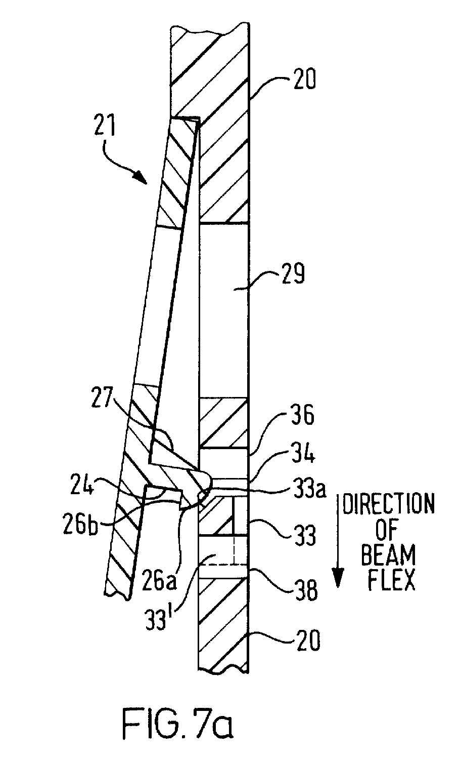
- the clip head 26a comes into contact with the chamfered portion 33a of the beam 33, it displaces the beam in the direction indicated in Figure 7a, referred to in this specification as downwards, since this generally corresponds to the normal orientation in which the phone would be held in use.
- the displaced beam 33' shown in dotted outline, is accommodated in the second (lower) slot 35, 38.
- the tabs 31 on the window panel 21 and the corresponding tab slots 30 in the front cover 20 are omitted, the window panel 21 fitting relatively tightly in the recessed portion 28 of the front cover and being held in place by the clip arrangement 24, 32 in conjunction with adhesive. It will be evident to a person skilled in the art that various other modifications to the form, details and dimensions of the clip arrangements may be made within the scope of the invention.
Landscapes
- Engineering & Computer Science (AREA)
- Signal Processing (AREA)
- Microelectronics & Electronic Packaging (AREA)
- Telephone Set Structure (AREA)
Abstract
Description
- This invention relates to the field of portable electronic apparatus such as mobile telephones, particularly but not exclusively to a housing assembly including a clip arrangement for securely attaching a display window to a mobile phone cover.
- The majority of conventional mobile telephones have a liquid crystal display for displaying information relating to mobile phone operation, such as the telephone number being dialled, address lists, phone settings and so on. The display is viewed through a protective plastic window, which forms part of the front housing of the phone. Figures 1a and 1b illustrate several conventional techniques for assembling parts of a housing. For example, referring to Figure 1a, the front housing 1 of a mobile telephone includes a
cover portion 2 and awindow panel 3, comprising a clear window 4 and aframe 5. Thewindow panel 3 is held in thecover portion 2 by layers ofadhesive 6, but this often fails at the higher operational temperatures which may result from prolonged phone use.Tabs 7 can be used to aid retention but often snap off if the phone is accidentally dropped. Furthermore, tabs can only be used at one end of thewindow panel 3 to allow assembly, so that the opposite end of thepanel 3 will peel away from thecover portion 2 and ultimately drop out if theadhesive 6 fails. - Referring to Figure 1b, a further known type of clipping arrangement comprises a
deformable clip 8 in onehousing part 9 which rides over alip 10a of a retainingmember 10 in themating housing part 11 and clips behind the retainingmember 10 to hold therespective housing parts mating part 11, which is not practical in small assemblies. - Clip arrangements are also known in which additional components such as metal spring arrangements are used to provide clip retaining features in one part of the housing. Such solutions increase manufacturing complexity and therefore the cost per unit manufactured.
- According to the present invention, there is provided a housing assembly for portable electronic apparatus comprising first and second housing portions, the first portion including a substantially rigid clip and the second portion including a receiving arrangement for the clip, the receiving arrangement comprising a displaceable element integrally moulded with the second portion, and the clip comprising means for displacing the element of the second portion, and means for retaining the element between the first portion and the displacing means.
- The displaceable element can be an elongate beam, which can be defined by first and second slots in the second portion. To assist with location of the first portion onto the second portion, the first slot can be configured to receive the clip only at a part thereof. Further, the beam can have a chamfered edge to assist with movement of the clip over the beam during assembly.
- The integrally moulded displaceable element obviates the need for additional components and allows the use of a substantially rigid clip, which is less likely to snap. Since a long clip is therefore not required, a low profile clip can advantageously be used to join two substantially planar housing portions, so that, when assembled, the clip does not protrude substantially beyond the plane of the second portion. This can have particular advantages in the manufacture of small assemblies where space is at a premium.
- In the case of a mobile telephone, the first portion can be a window panel and the second portion the front cover of the telephone.
- The clip arrangement can be used together with an adhesive and can have the significant advantage that the clip arrangement is itself capable of holding in the window after the adhesive has failed. The window portion can also include one or more tabs for engaging with the cover. The tabs and the clip are preferably arranged at opposite sides of the clear window in the window panel. Even if the tabs snap off, for example when the apparatus is dropped, the clip will remain to hold the window panel. The clip can be reinforced to ensure that it does not deform, so strengthening it further.
- Embodiments of the invention will now be described by way of example, with reference to the accompanying drawings, in which:
- Figure 1a shows a conventional display window assembly in a mobile telephone;
- Figure 1b shows a conventional deformable clip arrangement;
- Figure 2 is an exploded view of a mobile telephone according to the invention;
- Figure 3 is a rear view of the window panel of the telephone of Figure 2 showing the clip which forms part of the clip arrangement according to the invention;
- Figure 4 is an enlarged view of the clip shown in Figure 3;
- Figure 5 is a front view of the cover portion of the telephone of Figure 2 showing details of the clip receiving arrangement which forms part of the clip arrangement according to the invention;
- Figure 6a is an enlarged front view of the clip receiving arrangement shown in Figure 5;
- Figure 6b is an enlarged rear view of the clip receiving arrangement shown in Figure 5;
- Figure 7a is an enlarged cross-sectional view showing a first step in the assembly of the window panel of Figure 3 to the cover portion of Figure 5; and
- Figure 7b is an enlarged cross-sectional view showing the completed assembly of the window panel of Figure 3 to the cover portion of Figure 5.
-
- Referring to Figure 2, a mobile telephone which includes a housing assembly according to the invention comprises a
rear housing 12 including abattery pack 13, mobile telephone circuitry 14 including anLCD display panel 15,microphone 16, ear-piece 17,keypad 18 andantenna 19, a front housing portion referred to in this specification as afront cover 20 and awindow panel 21 which is designed to fit into the front cover so that theLCD display panel 15 is visible through it. The telephone circuitry 14 is of the type which is well known in the art, for example in the Nokia range of mobile telephones. - Referring to Figure 3, the
window panel 21 is a single piece plastic moulding having aclear window 22 and asurround 23, and is made by conventional moulding techniques using conventional materials. Alow profile clip 24 is integrally moulded with thepanel 21 so as to extend essentially perpendicular to the plane of the panel. The clip is shown in more detail in Figure 4. - Referring to Figure 4, the
clip 24 comprises abody portion 25 extending from thepanel 21 and abarbed head portion 26 having a rounded leadingedge 26a and atrailing edge 26b. Reinforcingstruts 27 are provided for additional strength. The dimensions of theclip 24 are, for example, approximately 1.8mm high (a), 3mm wide (b) and 1.8mm long (c). The reinforcingstruts 27 are, for example, 1.5mm high (d) and 1mm long (e). The barbed part of theclip head 26 is approximately 0.8mm long (f) and 1.5mm (g) from the surface of thewindow panel 21. - Referring to Figure 5, the
front cover 20 is a moulded plastic unit having arecessed portion 28 for receiving thewindow panel 21. The recess is, for example, approximately 1.5mm deep. Thefront cover 20 includes cut-outs 29 to accommodate theLCD display panel 15,microphone 16,earpiece 17 andkeypad 18, as well astab receiving slots 30 to accommodatecorresponding tabs 31 on thewindow panel 21. Thefront cover 20 also includes aclip receiving arrangement 32 which is shown in more detail in Figures 6a and 6b. - Referring to Figure 6a, the
clip receiving arrangement 32 is integrally moulded with the front cover and comprises a generallyelongate beam 33 defined by twoslots - The beam length is, for example, approximately 2cm to allow the beam to be sufficiently flexible so that it deforms without breaking on contact with the
clip 24. It has, for example, a square cross-section 1mm x 1mm. Thefirst slot 34 is wide enough to receive the clip only at acentral portion 36 thereof, the central portion being, for example, approximately 5mm long and 2mm wide, the remainder of the slot being 1mm wide. Thesecond slot 35 is sufficiently wide, for example, 1mm, to accommodate the beam when it is deflected from its usual position by the action of theclip 24. - The
beam 33 has a chamferedportion 33a which cooperates with therounded edge 26a of theclip head 26 to assist theclip head 26 to ride over the beam when the clip first contacts it during assembly. The beam can be formed with athicker portion 37 in the region of the chamfered portion to strengthen it. In this case, thesecond slot 35 is formed with anoffset portion 38 at the level of the thicker portion, to receive thebeam 33 as it flexes. - Referring to Figure 6b, the beam has a
recess 39 for receiving theclip head 26 to assist in ensuring that the head does not protrude significantly into the assembly. The recess is, for example, 6mm long and 0.3mm deep. - The operation of the clip arrangement will now be described in detail, with reference to Figures 7a and 7b.
- To assemble the
window panel 21 to thefront cover 20, thetabs 31 are first fitted into thetab slots 30. These then act as a pivot point allowing thepanel 21 to be pivoted into position over thefront cover 20. Referring to Figure 7a, as theclip head 26a comes into contact with the chamferedportion 33a of thebeam 33, it displaces the beam in the direction indicated in Figure 7a, referred to in this specification as downwards, since this generally corresponds to the normal orientation in which the phone would be held in use. The displaced beam 33', shown in dotted outline, is accommodated in the second (lower)slot edge 26b of theclip head 26 clears the side of thebeam 33b furthest from the window panel, the resilience of the beam material moves the beam upwards so that it locates between theclip head 26 and the surface of thewindow panel 21 from which theclip 24 extends, as shown in Figure 7b. Thewindow panel 21 is now firmly secured to thefront cover 20. An adhesive can be used between the window panel and the front cover in conjunction with the tabs and clipping arrangement. - In an alternative embodiment of the invention, the
tabs 31 on thewindow panel 21 and thecorresponding tab slots 30 in thefront cover 20 are omitted, thewindow panel 21 fitting relatively tightly in the recessedportion 28 of the front cover and being held in place by theclip arrangement - It will be appreciated that while the invention has been described in relation to mobile telephones, it can be used with any sort of portable electronic apparatus, for example, hand held computers and portable measuring equipment.
Claims (18)
- A housing assembly for portable electronic apparatus comprising first and second housing portions, the first portion including a substantially rigid clip and the second portion including a receiving arrangement for the clip, the receiving arrangement comprising a displaceable element integrally moulded with the second portion, and the clip comprising means for displacing the element of the second portion, and means for retaining the element between the first portion and the displacing means.
- An assembly according to claim 1, wherein the element comprises an elongate beam.
- An assembly according to claim 2, wherein the beam includes a chamfered edge to facilitate passage of the clip over it.
- An assembly according to claim 3, wherein the beam is reinforced in the region of the chamfered edge.
- An assembly according to any one of claims 2 to 4, wherein the beam is defined by first and second elongate slots in the second portion.
- An assembly according to claim 5, wherein the first elongate slot is configured to receive the clip and the second elongate slot is configured to receive the beam on displacement by the clip.
- An assembly according to claim 6, wherein only a part of the first elongate slot is capable of receiving the clip.
- An assembly according to any one of claims 2 to 7, wherein the clip includes a clip head and a clip body, the head, body and the first housing portion forming a receptacle for receiving the beam.
- An assembly according to claim 8, wherein the beam includes a recess for receiving the clip head.
- An assembly according to any one of the preceding claims, wherein the first and second portions are substantially planar.
- An assembly according to claim 10, wherein the clip extends substantially perpendicularly from the plane of the first portion.
- An assembly according to claim 10 or 11, wherein, in the assembled state, the clip does not protrude substantially beyond the plane of the second portion.
- An assembly according to any one of the preceding claims, wherein the first portion comprises a window panel for a mobile telephone and the second portion comprises a front housing for the mobile telephone.
- An assembly according to claim 13, further comprising tabs on the window panel for engaging with tab receiving slots in the front housing.
- An assembly according to claim 14, wherein the window panel includes a window for viewing a display of a mobile telephone, and the tabs and the clip are located on opposite sides of the window.
- A mobile telephone comprising an assembly according to any one of claims 10 to 15.
- A method of assembling a housing assembly according to any one of claims 1 to 15, comprising moving the first portion towards the second portion such that the displacing means on the clip of the first portion displaces the element of the second portion and then retains the element between the first portion and the displacing means.
- A portable telecommunications apparatus incorporating a housing assembly as claimed in any one of claims 1 to 15.
Applications Claiming Priority (2)
| Application Number | Priority Date | Filing Date | Title |
|---|---|---|---|
| GB9930246 | 1999-12-21 | ||
| GB9930246A GB2357546B (en) | 1999-12-21 | 1999-12-21 | Housing assembly for portable electronic apparatus |
Publications (1)
| Publication Number | Publication Date |
|---|---|
| EP1111976A1 true EP1111976A1 (en) | 2001-06-27 |
Family
ID=10866779
Family Applications (1)
| Application Number | Title | Priority Date | Filing Date |
|---|---|---|---|
| EP00309764A Withdrawn EP1111976A1 (en) | 1999-12-21 | 2000-11-03 | Window clipping arrangement |
Country Status (3)
| Country | Link |
|---|---|
| US (1) | US6842633B1 (en) |
| EP (1) | EP1111976A1 (en) |
| GB (1) | GB2357546B (en) |
Cited By (2)
| Publication number | Priority date | Publication date | Assignee | Title |
|---|---|---|---|---|
| WO2009083823A1 (en) * | 2007-12-28 | 2009-07-09 | Arcelik Anonim Sirketi | A display device |
| US8326377B2 (en) | 2007-03-16 | 2012-12-04 | Lg Electronics Inc. | Input device and mobile device having the same |
Families Citing this family (17)
| Publication number | Priority date | Publication date | Assignee | Title |
|---|---|---|---|---|
| US7194291B2 (en) * | 2001-06-26 | 2007-03-20 | Gregory Kim | Protective mask of mobile phone |
| CN100512328C (en) * | 2000-12-29 | 2009-07-08 | 弗图有限公司 | Casing |
| US7536210B1 (en) | 2005-12-09 | 2009-05-19 | Symbol Technologies, Inc. | Modular housing with housing plates |
| US20080167082A1 (en) * | 2007-01-10 | 2008-07-10 | Vladimir Gurevich | Incorporated indicating arrangement for a mobile device and related methods |
| US7836990B2 (en) * | 2007-06-26 | 2010-11-23 | Honda Motor Company, Ltd. | Battery boxes having aperture and vehicles including same |
| US7836989B2 (en) * | 2007-06-26 | 2010-11-23 | Honda Motor Company, Ltd. | Battery boxes and vehicles including same |
| CN101547577B (en) * | 2008-03-26 | 2012-07-04 | 深圳富泰宏精密工业有限公司 | Shell of electronic device |
| US7933123B2 (en) | 2008-04-11 | 2011-04-26 | Apple Inc. | Portable electronic device with two-piece housing |
| CN101577741B (en) * | 2008-05-09 | 2012-03-14 | 鸿富锦精密工业(深圳)有限公司 | Mobile phone shell |
| TWI410111B (en) * | 2008-05-16 | 2013-09-21 | Hon Hai Prec Ind Co Ltd | Front cover of a mobile phone |
| US7843688B2 (en) * | 2008-06-25 | 2010-11-30 | Nokia Corporation | Latching mechanisms for portable electronic devices |
| CN103378325A (en) * | 2012-04-25 | 2013-10-30 | 深圳富泰宏精密工业有限公司 | Battery cover locking structure |
| US8955678B2 (en) | 2013-03-14 | 2015-02-17 | Pelican Products, Inc. | Protective cases for mobile electronic communication devices |
| TWI578875B (en) * | 2015-08-31 | 2017-04-11 | King Slide Technology Co Ltd | Housing mounting mechanism of portable electronic device |
| WO2017127536A1 (en) * | 2016-01-19 | 2017-07-27 | Beam Authentic, Inc. | Mobile device case for holding a display device |
| US9831905B1 (en) | 2016-10-12 | 2017-11-28 | Pelican Products, Inc. | Control feature of a protective case for engaging a switch of an electronic device |
| US10757238B1 (en) * | 2019-08-14 | 2020-08-25 | Scott S. Porta | Cell phone attachment |
Citations (6)
| Publication number | Priority date | Publication date | Assignee | Title |
|---|---|---|---|---|
| CH659164A5 (en) * | 1983-05-16 | 1986-12-31 | Gfeller Ag | Housing to receive an electronic device |
| GB2197383A (en) * | 1986-11-15 | 1988-05-18 | Plessey Co Plc | Interlocking mechanism |
| EP0330744A2 (en) * | 1988-02-29 | 1989-09-06 | Hewlett-Packard Company | Locking system |
| EP0491270A2 (en) * | 1990-12-19 | 1992-06-24 | Mannesmann Kienzle GmbH (HR B1220) | Fixture for assembling two parts of a case |
| DE9416849U1 (en) * | 1994-10-19 | 1995-03-02 | Siemens AG, 80333 München | Holder for a display within a telephone station |
| DE29911091U1 (en) * | 1999-06-25 | 1999-10-21 | Loewe Opta GmbH, 96317 Kronach | Joint connection for the detachable connection of two housing parts |
Family Cites Families (17)
| Publication number | Priority date | Publication date | Assignee | Title |
|---|---|---|---|---|
| FR2507707B1 (en) * | 1981-06-12 | 1985-09-06 | Chausson Usines Sa | DEVICE FOR THE MUTUAL ASSEMBLY OF TWO PARTS TO BE DISASSEMBLED OCCASIONALLY |
| GB2147653A (en) * | 1983-10-10 | 1985-05-15 | Trw Carr Ltd | Two part snap fastening |
| US4803473A (en) * | 1987-11-09 | 1989-02-07 | Dicon Systems Limited | Transmitter cover |
| US5210532A (en) * | 1991-09-03 | 1993-05-11 | Gerry Baby Products Company | Baby monitor receiver having indicator display and dual position clip |
| US5535274A (en) * | 1991-10-19 | 1996-07-09 | Cellport Labs, Inc. | Universal connection for cellular telephone interface |
| US5233506A (en) * | 1992-02-21 | 1993-08-03 | Motorola, Inc. | Fastener for housing assembly |
| GB2310103B (en) * | 1996-02-06 | 1999-07-07 | Nokia Mobile Phones Ltd | LCD Support frame |
| US5666274A (en) * | 1996-02-08 | 1997-09-09 | Jtech Inc. | Rapid assembly portable electronic device and clip |
| DE19605373C2 (en) * | 1996-02-14 | 1998-11-19 | Bosch Gmbh Robert | Device with a display device |
| US5697071A (en) * | 1996-05-02 | 1997-12-09 | Fan; Eagle | Mobile phone holder structure |
| GB2314230B (en) * | 1996-06-12 | 2000-04-26 | Nec Technologies | Mobile phone hand set |
| US5768370A (en) * | 1997-01-08 | 1998-06-16 | Nokia Mobile Phones, Ltd. | User changeable cosmetic phone interface |
| GB2322501B (en) * | 1997-02-21 | 2000-08-02 | Nokia Mobile Phones Ltd | Display window for handset |
| DE69826812T2 (en) * | 1997-11-28 | 2005-10-06 | Koninklijke Philips Electronics N.V. | Plug connection system for plastic trays |
| US6115620A (en) * | 1998-05-20 | 2000-09-05 | Motorola, Inc. | Mode-switchable portable communication device and method therefor |
| ATE222673T1 (en) * | 1999-02-01 | 2002-09-15 | Ericsson Telefon Ab L M | COMMUNICATION STATION |
| US6389268B1 (en) * | 1999-07-29 | 2002-05-14 | Ericsson Inc. | Electronic device holders with display panel magnifier |
-
1999
- 1999-12-21 GB GB9930246A patent/GB2357546B/en not_active Expired - Fee Related
-
2000
- 2000-11-03 EP EP00309764A patent/EP1111976A1/en not_active Withdrawn
- 2000-11-14 US US09/712,820 patent/US6842633B1/en not_active Expired - Fee Related
Patent Citations (6)
| Publication number | Priority date | Publication date | Assignee | Title |
|---|---|---|---|---|
| CH659164A5 (en) * | 1983-05-16 | 1986-12-31 | Gfeller Ag | Housing to receive an electronic device |
| GB2197383A (en) * | 1986-11-15 | 1988-05-18 | Plessey Co Plc | Interlocking mechanism |
| EP0330744A2 (en) * | 1988-02-29 | 1989-09-06 | Hewlett-Packard Company | Locking system |
| EP0491270A2 (en) * | 1990-12-19 | 1992-06-24 | Mannesmann Kienzle GmbH (HR B1220) | Fixture for assembling two parts of a case |
| DE9416849U1 (en) * | 1994-10-19 | 1995-03-02 | Siemens AG, 80333 München | Holder for a display within a telephone station |
| DE29911091U1 (en) * | 1999-06-25 | 1999-10-21 | Loewe Opta GmbH, 96317 Kronach | Joint connection for the detachable connection of two housing parts |
Cited By (2)
| Publication number | Priority date | Publication date | Assignee | Title |
|---|---|---|---|---|
| US8326377B2 (en) | 2007-03-16 | 2012-12-04 | Lg Electronics Inc. | Input device and mobile device having the same |
| WO2009083823A1 (en) * | 2007-12-28 | 2009-07-09 | Arcelik Anonim Sirketi | A display device |
Also Published As
| Publication number | Publication date |
|---|---|
| US6842633B1 (en) | 2005-01-11 |
| GB2357546B (en) | 2003-08-27 |
| GB2357546A (en) | 2001-06-27 |
| GB9930246D0 (en) | 2000-02-09 |
Similar Documents
| Publication | Publication Date | Title |
|---|---|---|
| US6842633B1 (en) | Clip arrangement for portable electronic apparatus housing assembly | |
| US6148183A (en) | Switch assembly for an electronic device | |
| US6495784B2 (en) | Step keys, step key assembly, and terminal having the step key assembly | |
| US7443351B2 (en) | Portable terminal | |
| US20040109559A1 (en) | Folder type mobile terminal | |
| CN113364902B (en) | Dustproof assembly and folding electronic device | |
| CN100409648C (en) | Foldable Mobile Terminal | |
| EP1406204B1 (en) | Card holder for cellular phone | |
| EP1536365B1 (en) | Card holding structure for portable electronic device | |
| US20110157782A1 (en) | Housing assembly for a portable electronic device | |
| IL132457A (en) | Microphone connecting device for flip type portable telephone | |
| JP2000349875A (en) | Wireless communication device, battery pack and connector | |
| US20110124246A1 (en) | Electronic device with grounding mechanism | |
| CN100521559C (en) | Portable telephone | |
| JP2000155306A (en) | Display device | |
| KR20020035294A (en) | structure for assembling to display of mobile communication terminal | |
| EP1638379A2 (en) | Structure for preventing stacking connectors on boards from coming apart and electronic device | |
| JPH11307191A (en) | Card connector | |
| US20040121824A1 (en) | Folder type mobile terminal | |
| JP2001102017A (en) | Thin battery with pack structure | |
| JP2004252251A (en) | Display device and information equipment | |
| JP2002164028A (en) | Battery pack mounting structure | |
| US20070128914A1 (en) | Chip card retaining mechanism | |
| CN221354361U (en) | protective case | |
| JP4429147B2 (en) | Lid for portable information terminal and portable information terminal |
Legal Events
| Date | Code | Title | Description |
|---|---|---|---|
| PUAI | Public reference made under article 153(3) epc to a published international application that has entered the european phase |
Free format text: ORIGINAL CODE: 0009012 |
|
| AK | Designated contracting states |
Kind code of ref document: A1 Designated state(s): DE FR IT NL Kind code of ref document: A1 Designated state(s): AT BE CH CY DE DK ES FI FR GB GR IE IT LI LU MC NL PT SE TR |
|
| AX | Request for extension of the european patent |
Free format text: AL;LT;LV;MK;RO;SI |
|
| 17P | Request for examination filed |
Effective date: 20011023 |
|
| RAP1 | Party data changed (applicant data changed or rights of an application transferred) |
Owner name: NOKIA CORPORATION |
|
| AKX | Designation fees paid |
Free format text: DE FR IT NL |
|
| STAA | Information on the status of an ep patent application or granted ep patent |
Free format text: STATUS: THE APPLICATION HAS BEEN WITHDRAWN |
|
| 18W | Application withdrawn |
Effective date: 20040921 |