EP0330744A2 - Locking system - Google Patents
Locking system Download PDFInfo
- Publication number
- EP0330744A2 EP0330744A2 EP88120111A EP88120111A EP0330744A2 EP 0330744 A2 EP0330744 A2 EP 0330744A2 EP 88120111 A EP88120111 A EP 88120111A EP 88120111 A EP88120111 A EP 88120111A EP 0330744 A2 EP0330744 A2 EP 0330744A2
- Authority
- EP
- European Patent Office
- Prior art keywords
- workpiece
- arm
- locking
- elongated
- accordance
- Prior art date
- Legal status (The legal status is an assumption and is not a legal conclusion. Google has not performed a legal analysis and makes no representation as to the accuracy of the status listed.)
- Granted
Links
- 230000013011 mating Effects 0.000 claims 2
- 230000003405 preventing effect Effects 0.000 abstract description 2
- 238000000034 method Methods 0.000 description 2
- 238000012986 modification Methods 0.000 description 2
- 230000004048 modification Effects 0.000 description 2
- 239000000853 adhesive Substances 0.000 description 1
- 230000001070 adhesive effect Effects 0.000 description 1
- 230000007246 mechanism Effects 0.000 description 1
- 229920000136 polysorbate Polymers 0.000 description 1
Images


Classifications
-
- F—MECHANICAL ENGINEERING; LIGHTING; HEATING; WEAPONS; BLASTING
- F16—ENGINEERING ELEMENTS AND UNITS; GENERAL MEASURES FOR PRODUCING AND MAINTAINING EFFECTIVE FUNCTIONING OF MACHINES OR INSTALLATIONS; THERMAL INSULATION IN GENERAL
- F16B—DEVICES FOR FASTENING OR SECURING CONSTRUCTIONAL ELEMENTS OR MACHINE PARTS TOGETHER, e.g. NAILS, BOLTS, CIRCLIPS, CLAMPS, CLIPS OR WEDGES; JOINTS OR JOINTING
- F16B5/00—Joining sheets or plates, e.g. panels, to one another or to strips or bars parallel to them
- F16B5/07—Joining sheets or plates, e.g. panels, to one another or to strips or bars parallel to them by means of multiple interengaging protrusions on the surfaces, e.g. hooks, coils
-
- F—MECHANICAL ENGINEERING; LIGHTING; HEATING; WEAPONS; BLASTING
- F16—ENGINEERING ELEMENTS AND UNITS; GENERAL MEASURES FOR PRODUCING AND MAINTAINING EFFECTIVE FUNCTIONING OF MACHINES OR INSTALLATIONS; THERMAL INSULATION IN GENERAL
- F16B—DEVICES FOR FASTENING OR SECURING CONSTRUCTIONAL ELEMENTS OR MACHINE PARTS TOGETHER, e.g. NAILS, BOLTS, CIRCLIPS, CLAMPS, CLIPS OR WEDGES; JOINTS OR JOINTING
- F16B21/00—Means for preventing relative axial movement of a pin, spigot, shaft or the like and a member surrounding it; Stud-and-socket releasable fastenings
- F16B21/06—Releasable fastening devices with snap-action
- F16B21/07—Releasable fastening devices with snap-action in which the socket has a resilient part
- F16B21/071—Releasable fastening devices with snap-action in which the socket has a resilient part the socket being integrally formed with a component to be fasted, e.g. a sheet, plate or strip
-
- F—MECHANICAL ENGINEERING; LIGHTING; HEATING; WEAPONS; BLASTING
- F16—ENGINEERING ELEMENTS AND UNITS; GENERAL MEASURES FOR PRODUCING AND MAINTAINING EFFECTIVE FUNCTIONING OF MACHINES OR INSTALLATIONS; THERMAL INSULATION IN GENERAL
- F16B—DEVICES FOR FASTENING OR SECURING CONSTRUCTIONAL ELEMENTS OR MACHINE PARTS TOGETHER, e.g. NAILS, BOLTS, CIRCLIPS, CLAMPS, CLIPS OR WEDGES; JOINTS OR JOINTING
- F16B21/00—Means for preventing relative axial movement of a pin, spigot, shaft or the like and a member surrounding it; Stud-and-socket releasable fastenings
- F16B21/06—Releasable fastening devices with snap-action
-
- H—ELECTRICITY
- H05—ELECTRIC TECHNIQUES NOT OTHERWISE PROVIDED FOR
- H05K—PRINTED CIRCUITS; CASINGS OR CONSTRUCTIONAL DETAILS OF ELECTRIC APPARATUS; MANUFACTURE OF ASSEMBLAGES OF ELECTRICAL COMPONENTS
- H05K5/00—Casings, cabinets or drawers for electric apparatus
- H05K5/0004—Casings, cabinets or drawers for electric apparatus comprising several parts forming a closed casing
- H05K5/0013—Casings, cabinets or drawers for electric apparatus comprising several parts forming a closed casing assembled by resilient members
-
- F—MECHANICAL ENGINEERING; LIGHTING; HEATING; WEAPONS; BLASTING
- F16—ENGINEERING ELEMENTS AND UNITS; GENERAL MEASURES FOR PRODUCING AND MAINTAINING EFFECTIVE FUNCTIONING OF MACHINES OR INSTALLATIONS; THERMAL INSULATION IN GENERAL
- F16B—DEVICES FOR FASTENING OR SECURING CONSTRUCTIONAL ELEMENTS OR MACHINE PARTS TOGETHER, e.g. NAILS, BOLTS, CIRCLIPS, CLAMPS, CLIPS OR WEDGES; JOINTS OR JOINTING
- F16B2200/00—Constructional details of connections not covered for in other groups of this subclass
- F16B2200/20—Connections with hook-like parts gripping behind a blind side of an element to be connected
- F16B2200/205—Connections with hook-like parts gripping behind a blind side of an element to be connected the hook being a separate retainer
-
- F—MECHANICAL ENGINEERING; LIGHTING; HEATING; WEAPONS; BLASTING
- F16—ENGINEERING ELEMENTS AND UNITS; GENERAL MEASURES FOR PRODUCING AND MAINTAINING EFFECTIVE FUNCTIONING OF MACHINES OR INSTALLATIONS; THERMAL INSULATION IN GENERAL
- F16B—DEVICES FOR FASTENING OR SECURING CONSTRUCTIONAL ELEMENTS OR MACHINE PARTS TOGETHER, e.g. NAILS, BOLTS, CIRCLIPS, CLAMPS, CLIPS OR WEDGES; JOINTS OR JOINTING
- F16B2200/00—Constructional details of connections not covered for in other groups of this subclass
- F16B2200/69—Redundant disconnection blocking means
-
- Y—GENERAL TAGGING OF NEW TECHNOLOGICAL DEVELOPMENTS; GENERAL TAGGING OF CROSS-SECTIONAL TECHNOLOGIES SPANNING OVER SEVERAL SECTIONS OF THE IPC; TECHNICAL SUBJECTS COVERED BY FORMER USPC CROSS-REFERENCE ART COLLECTIONS [XRACs] AND DIGESTS
- Y10—TECHNICAL SUBJECTS COVERED BY FORMER USPC
- Y10T—TECHNICAL SUBJECTS COVERED BY FORMER US CLASSIFICATION
- Y10T24/00—Buckles, buttons, clasps, etc.
- Y10T24/45—Separable-fastener or required component thereof [e.g., projection and cavity to complete interlock]
- Y10T24/45225—Separable-fastener or required component thereof [e.g., projection and cavity to complete interlock] including member having distinct formations and mating member selectively interlocking therewith
- Y10T24/45471—Projection having movable connection between components thereof or variable configuration
- Y10T24/45524—Projection having movable connection between components thereof or variable configuration including resiliently biased projection component or surface segment
- Y10T24/45545—Projection having movable connection between components thereof or variable configuration including resiliently biased projection component or surface segment forming total external surface of projection
- Y10T24/45581—Projection having movable connection between components thereof or variable configuration including resiliently biased projection component or surface segment forming total external surface of projection having inserted end formed by oppositely biased surface segments
-
- Y—GENERAL TAGGING OF NEW TECHNOLOGICAL DEVELOPMENTS; GENERAL TAGGING OF CROSS-SECTIONAL TECHNOLOGIES SPANNING OVER SEVERAL SECTIONS OF THE IPC; TECHNICAL SUBJECTS COVERED BY FORMER USPC CROSS-REFERENCE ART COLLECTIONS [XRACs] AND DIGESTS
- Y10—TECHNICAL SUBJECTS COVERED BY FORMER USPC
- Y10T—TECHNICAL SUBJECTS COVERED BY FORMER US CLASSIFICATION
- Y10T24/00—Buckles, buttons, clasps, etc.
- Y10T24/45—Separable-fastener or required component thereof [e.g., projection and cavity to complete interlock]
- Y10T24/45225—Separable-fastener or required component thereof [e.g., projection and cavity to complete interlock] including member having distinct formations and mating member selectively interlocking therewith
- Y10T24/45602—Receiving member includes either movable connection between interlocking components or variable configuration cavity
- Y10T24/45775—Receiving member includes either movable connection between interlocking components or variable configuration cavity having resiliently biased interlocking component or segment
- Y10T24/45785—Requiring manual force applied against bias to interlock or disengage
-
- Y—GENERAL TAGGING OF NEW TECHNOLOGICAL DEVELOPMENTS; GENERAL TAGGING OF CROSS-SECTIONAL TECHNOLOGIES SPANNING OVER SEVERAL SECTIONS OF THE IPC; TECHNICAL SUBJECTS COVERED BY FORMER USPC CROSS-REFERENCE ART COLLECTIONS [XRACs] AND DIGESTS
- Y10—TECHNICAL SUBJECTS COVERED BY FORMER USPC
- Y10T—TECHNICAL SUBJECTS COVERED BY FORMER US CLASSIFICATION
- Y10T403/00—Joints and connections
- Y10T403/16—Joints and connections with adjunctive protector, broken parts retainer, repair, assembly or disassembly feature
- Y10T403/1616—Position or guide means
- Y10T403/1624—Related to joint component
Definitions
- This invention relates to systems and techniques for detachably securing two items together. More particularly, this invention relates to systems and techniques for detach severelyably securing two workpieces together (e.g., two sections of a housing).
- housing sections used to enclose or contain a product must be fastened in some manner so as to be secure when the product is used, but preferably the housing sections are detachable so that they can be removed to allow access to the product (e.g., for repair purposes).
- Such products require the type of enclosure or containment described.
- Such products include, for example, gears, electronics, linkages, tubing or wiring which must be clamped or secured in place, and other various mechanisms.
- the workpieces may be housings for electrical components, mounting or clamping devices, or locating components of a mechanical gear train or linkage.
- fastening devices can be used to detachably secure items such as housing sections to each other or to a product to be enclosed.
- various types of threaded fasteners or other mechanical fasteners have been used for this purpose.
- this requires that additional components be used, thereby increasing the cost of the enclosure.
- hook and loop fasteners such as Velcro brand fasteners
- over-center latches such as Velcro brand fasteners
- press fit fasteners e.g., where a post is pushed into an opening with great force to frictionally engage the walls of the opening.
- Hook and loop fasteners have structural limitations. Latches can be complex and also costly. Press fit fasteners may lose their effectiveness after being detached one or more times.
- a locking system for detachably securing two workpieces such as housing sections together.
- the locking system comprises:
- the second end of the elongated arm can be deflected by the lead in ramp means when the first workpiece is urged toward the second workpiece. This enables the second end of the elongated arm to pass through the opening.
- the locking arm is movable to its closed position behind the second end of the elongated arm to restrict movement of the second end.
- the hook portion or engagement means on the end of the elongated arm engages the second workpiece. The locking arm prevents the hook portion of the elongated arm from backing out of the opening in the second workpiece when the elongated arm is loaded in tension, thereby preventing the previously-described failure.
- Unlocking requires that the locking arm be moved from its closed to its open position. Then the second end of the elongated arm can be deflected so that the hook portion or engagement means is released from the second workpiece, allowing the elongated arm to be moved out of the opening in the second workpiece.
- elongated arms carried by the first workpiece and a corresponding plurality of openings in the second workpieces.
- the two workpieces may be housing sections which are used to enclose a product (e.g., a gear train, electronics system, etc.)
- a product e.g., a gear train, electronics system, etc.
- the locking system illustrated includes pairs of elongated, parallel arms 12 and 14. At one end the parallel arms are secured to one of the workpieces 40. Preferably, the arms are integrally molded as a part of the workpiece 40. Alternatively, the arms could be attached to the workpiece with adhesive or other fasteners.
- the second workpiece 50 includes a plurality of openings 18 corresponding to rhe number of pairs of parallel arms carried by the first workpiece 40.
- the locking arm is integral with the work piece at one end in a manner such that the opposite end of the locking arm is deflectable out of the opening but will return to its normal position within the opening.
- the outer ends of the elongated arms 12 and 14 include hook portions 13 and 15, respectively.
- the outer ends of the arms are resiliently deflectable so that they may be urged towards each other to fit within the corresponding opening in the second workpiece Then the arms spring away from each other again in a manner such that the hook portions 13 and 15 engage the second workpiece.
- the locking arm can then deflect back to its closed position where it is situated between the ends of the elongated arms to restrict movement of the ends towards each other.
- Figures 2-5 These features are illustrated in Figures 2-5.
- the outer ends of the elongated arms 12 and 14 are shown contacting the lead in ramp members 20 and 21, respectively, which are located adjacent opposite side edges of opening 18.
- the lead in ramp members serve as guide members to urge the outer ends of the elongated arms towards each other when the first workpiece 40 is moved toward the second workpiece 50.
- the locking arm prevents the elongated arms from coming loose from the second workpiece when tension is applied to the elongated arms. Yet the two workpieces can be easily separated from each other when desired by first moving each locking arm 22 away from the ends of the arms 12 and 14 to allow them to be moved towards each other. In this manner the hook portions are disengaged from the second workpiece.
- side walls 23 and 24 of workpiece 40 serve to establish the desired minimum spacing between the two workpieces. Thus, when the sidewalls contact the other workpiece the desired spacing is maintained.
- FIG. 7 Another manner of establishing the desired spacing between the two workpieces is illustrated in Figure 7.
- the other workpiece 70 includes an opening 71 in which a locking arm 72 is disposed.
- Ramp member 74 is carried by workpiece 70 adjacent one edge of opening 71.
- ramp member 74 guides the end of arm 60 into opening 71 where it deflects the upper end of locking arm 72 out of opening 71. Then when the end of arm 60 is through opening 71, locking arm 72 springs back behind arm 60 so that hook member 62 remains in engagement with workpiece 70.
- Ledge or stop member 64 on arm 60 serves to limit the extent to which arm 60 may pass through opening 71. In this manner the minimum spacing between the two workpieces is maintained.
- Positional alignment between the two workpieces may be provided by referencing pins 25 on one workpiece and alignment apertures 26 on the other workpiece, as illustrated in Figure 1. Such alignment is not required in all cases but it may be helpful in situations where a high degree of positional accuracy is required.
- Figure 6 illustrates another embodiment of the locking system of this invention.
- One workpiece 30 includes opening 31.
- Locking arm 33 is disposed in opening 31, as illustrated.
- Ramp member 32 is carried by workpiece 30 adjacent the top edge of opening 31.
- An elongated arm 42 carried by another workpiece (not shown) is adapted to pass through opening 31 in workpiece 30.
- the outer or free end of arm 42 includes an upstanding wall or hook member 43 which is adapted to engage the outer surface of workpiece 30 after it has been passed through opening 31.
- the leading end of arm 42 includes a ramp member 44 to assist in guiding this end of arm 42 into opening 31 when the two workpieces are brought together.
- Locking arm 33 is deflected out of opening 31 by the end of arm 42. Then arm 33 springs back into its original position where it holds arm 42 against the upper edge of opening 31. This assures that hook portion 43 is maintained in engagement with workpiece 30.
- the locking arm 33 is deflected out of the way. Then the arm 42 can be deflected downwardly so that the hook member 43 is disengaged from workpiece 30. At that point the arm 42 may be moved out of opening 31.
- two of the arms may be adapted to engage the second workpiece along side edges of the opening while the third arm is adapted to enage the second workpiece along the top edge of the opening.
Landscapes
- Engineering & Computer Science (AREA)
- General Engineering & Computer Science (AREA)
- Mechanical Engineering (AREA)
- Microelectronics & Electronic Packaging (AREA)
- Clamps And Clips (AREA)
- Insertion Pins And Rivets (AREA)
- Snaps, Bayonet Connections, Set Pins, And Snap Rings (AREA)
- Jigs For Machine Tools (AREA)
- Connection Of Plates (AREA)
Abstract
Description
- This invention relates to systems and techniques for detachably securing two items together. More particularly, this invention relates to systems and techniques for detachably securing two workpieces together (e.g., two sections of a housing).
- There are many situations where it is necessary or desirable to detachably secure two items or workpieces together. For example, housing sections used to enclose or contain a product must be fastened in some manner so as to be secure when the product is used, but preferably the housing sections are detachable so that they can be removed to allow access to the product (e.g., for repair purposes).
- Various types of products require the type of enclosure or containment described. Such products include, for example, gears, electronics, linkages, tubing or wiring which must be clamped or secured in place, and other various mechanisms. The workpieces may be housings for electrical components, mounting or clamping devices, or locating components of a mechanical gear train or linkage.
- Various types of fastening devices can be used to detachably secure items such as housing sections to each other or to a product to be enclosed. For example, various types of threaded fasteners or other mechanical fasteners have been used for this purpose. However, this requires that additional components be used, thereby increasing the cost of the enclosure.
- The use of a conventional cantilever beam with a hook on its outer end is also known as a means for securing two workpieces together. In such case, the outer end of the cantilever beam is inserted into an opening in the second workpiece. However, when a tensile load is exerted on the arm it can pull free of the second workpiece relatively easily. This is because the force exerted on the hook portion of a cantilever beam is not centrally applied to the beam. As a result, when a tensile load is exerted on the arm a moment is created which forces the beam to deflect. As the beam deflects, the angle of the hook portion changes such that a component of the force pushes the end of the beam back even further. Eventually the hook portion slips free and the workpieces become detached.
- Other conventional types of fastening systems include hook and loop fasteners (such as Velcro brand fasteners), over-center latches, and press fit fasteners (e.g., where a post is pushed into an opening with great force to frictionally engage the walls of the opening). Each of these systems has limitations, however. Hook and loop fasteners have structural limitations. Latches can be complex and also costly. Press fit fasteners may lose their effectiveness after being detached one or more times.
- There has not heretofore been provided a locking system of the type described herein for detachably securing two workpieces together.
- In accordance with the present invention there is provided a locking system for detachably securing two workpieces such as housing sections together. In one embodiment the locking system comprises:
- (a) one or more elongated arms having first and second ends, wherein the first end of each such arm is secured to the first workpiece, wherein the elongated arm projects outwardly from the first workpiece; wherein the second end is resiliently deflectable; and wherein the second end includes a hook portion or other engagement means;
- (b) an opening in the second workpiece;
- (c) lead in ramp means adapted to guide the second end of the elongated arm into the opening in the second workpiece;
- (d) a locking arm carried by the second workpiece, the locking arm being movable between an open position and a closed position.
- The second end of the elongated arm can be deflected by the lead in ramp means when the first workpiece is urged toward the second workpiece. This enables the second end of the elongated arm to pass through the opening. The locking arm is movable to its closed position behind the second end of the elongated arm to restrict movement of the second end. The hook portion or engagement means on the end of the elongated arm engages the second workpiece. The locking arm prevents the hook portion of the elongated arm from backing out of the opening in the second workpiece when the elongated arm is loaded in tension, thereby preventing the previously-described failure.
- Unlocking requires that the locking arm be moved from its closed to its open position. Then the second end of the elongated arm can be deflected so that the hook portion or engagement means is released from the second workpiece, allowing the elongated arm to be moved out of the opening in the second workpiece.
- Preferably there are a plurality of such elongated arms carried by the first workpiece and a corresponding plurality of openings in the second workpieces. If desired, there may also be one or more of such elongated arms on the second workpiece, and one or more corresponding openings in the first workpiece.
- In another embodiment there are a plurality of pairs of elongated arms carried by the first workpiece. After the free ends of the arms are passed through an opening in the second workpiece, the locking arm moves to its closed position between the parallel arms to restrict movement of the arms towards each other.
- Other advantages of the locking systems of this invention will be apparent from the following detailed description and the accompanying drawings.
- The invention is described in more detail hereinafter with reference to the accompanying drawings, wherein like reference characters refer to the same parts throughout the several views and in which:
- FIGURE 1 is a perspective view of two housing sections which are adapted to be detachably secured together using the locking system of the invention;
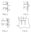
- FIGURES 2, 3 and 4 are top views (partially cut-away) of the locking system illustrating the manner in which the elongated arms are guided into an opening in the second workpiece and locked in position;
- FIGURE 5 is a side elevational view showing the arms secured to the second workpiece;
- FIGURE 6 is a perspective view of another embodiment of locking system of this invention; and
- FIGURE 7 is a perspective view illustrating another embodiment of locking system of this invention
- In Figures 1-5 there is illustrated one embodiment of locking system of the invention. As illustrated in the drawings, the two workpieces may be housing sections which are used to enclose a product (e.g., a gear train, electronics system, etc.)
- The locking system illustrated includes pairs of elongated,
parallel arms workpieces 40. Preferably, the arms are integrally molded as a part of theworkpiece 40. Alternatively, the arms could be attached to the workpiece with adhesive or other fasteners. - The
second workpiece 50 includes a plurality ofopenings 18 corresponding to rhe number of pairs of parallel arms carried by thefirst workpiece 40. On the interior surface of the second workpiece there are shown lead inramp members opening 18. Extending into the opening 18 is alocking arm 22 which is movable between an open position and a closed position. Preferably the locking arm is integral with the work piece at one end in a manner such that the opposite end of the locking arm is deflectable out of the opening but will return to its normal position within the opening. - The outer ends of the
elongated arms hook portions hook portions - These features are illustrated in Figures 2-5. In Figure 2 the outer ends of the
elongated arms ramp members opening 18. The lead in ramp members serve as guide members to urge the outer ends of the elongated arms towards each other when thefirst workpiece 40 is moved toward thesecond workpiece 50. - In Figure 3 the outer ends of the
arms opening 18 in the second workpiece. At the same time the outer ends urge or deflect the free end of lockingarm 22 outwardly away from the opening. - In Figure 4 the outer ends of
arms opening 18 and have sprung outwardly so that the hook portions have engaged the second workpiece. The free end of the locking arm has deflected back to its normal closed position withinopening 18. In this position the locking arm is positioned between the outer ends of the elongated arms to prevent them from moving towards each other. - Thus, the locking arm prevents the elongated arms from coming loose from the second workpiece when tension is applied to the elongated arms. Yet the two workpieces can be easily separated from each other when desired by first moving each locking
arm 22 away from the ends of thearms - As shown in Figure 1,
side walls workpiece 40 serve to establish the desired minimum spacing between the two workpieces. Thus, when the sidewalls contact the other workpiece the desired spacing is maintained. - Another manner of establishing the desired spacing between the two workpieces is illustrated in Figure 7. In this figure there is shown the free end of an
elongated arm 60 which is supported by one workpiece (not shown). Theother workpiece 70 includes anopening 71 in which alocking arm 72 is disposed.Ramp member 74 is carried byworkpiece 70 adjacent one edge ofopening 71. - When elongated
arm 60 is moved towardsworkpiece 70,ramp member 74 guides the end ofarm 60 intoopening 71 where it deflects the upper end of lockingarm 72 out ofopening 71. Then when the end ofarm 60 is throughopening 71, lockingarm 72 springs back behindarm 60 so thathook member 62 remains in engagement withworkpiece 70. Ledge or stopmember 64 onarm 60 serves to limit the extent to whicharm 60 may pass throughopening 71. In this manner the minimum spacing between the two workpieces is maintained. - Positional alignment between the two workpieces may be provided by referencing
pins 25 on one workpiece andalignment apertures 26 on the other workpiece, as illustrated in Figure 1. Such alignment is not required in all cases but it may be helpful in situations where a high degree of positional accuracy is required. - Figure 6 illustrates another embodiment of the locking system of this invention. One
workpiece 30 includesopening 31. Lockingarm 33 is disposed in opening 31, as illustrated.Ramp member 32 is carried byworkpiece 30 adjacent the top edge ofopening 31. - An
elongated arm 42 carried by another workpiece (not shown) is adapted to pass through opening 31 inworkpiece 30. The outer or free end ofarm 42 includes an upstanding wall orhook member 43 which is adapted to engage the outer surface ofworkpiece 30 after it has been passed throughopening 31. The leading end ofarm 42 includes a ramp member 44 to assist in guiding this end ofarm 42 intoopening 31 when the two workpieces are brought together. - Locking
arm 33 is deflected out of opening 31 by the end ofarm 42. Thenarm 33 springs back into its original position where it holdsarm 42 against the upper edge ofopening 31. This assures thathook portion 43 is maintained in engagement withworkpiece 30. - In order to detach one workpiece from the other, the locking
arm 33 is deflected out of the way. Then thearm 42 can be deflected downwardly so that thehook member 43 is disengaged fromworkpiece 30. At that point thearm 42 may be moved out ofopening 31. - Other embodiments are also possible. For example, there may be three elongated arms which are adapted to be passed through a single opening in the other workpiece. In such embodiment two of the arms may be adapted to engage the second workpiece along side edges of the opening while the third arm is adapted to enage the second workpiece along the top edge of the opening.
- Other changes and modifications will be readily apparent to those skilled in the art, and all such changes and modifications are considered to fall within the scope of this invention, as defined in the appended claims.
Claims (20)
Applications Claiming Priority (2)
| Application Number | Priority Date | Filing Date | Title |
|---|---|---|---|
| US07/161,560 US4844645A (en) | 1988-02-29 | 1988-02-29 | Locking system |
| US161560 | 1988-02-29 |
Publications (3)
| Publication Number | Publication Date |
|---|---|
| EP0330744A2 true EP0330744A2 (en) | 1989-09-06 |
| EP0330744A3 EP0330744A3 (en) | 1990-08-01 |
| EP0330744B1 EP0330744B1 (en) | 1994-02-16 |
Family
ID=22581695
Family Applications (1)
| Application Number | Title | Priority Date | Filing Date |
|---|---|---|---|
| EP88120111A Expired - Lifetime EP0330744B1 (en) | 1988-02-29 | 1988-12-02 | Locking system |
Country Status (8)
| Country | Link |
|---|---|
| US (1) | US4844645A (en) |
| EP (1) | EP0330744B1 (en) |
| JP (1) | JP2664461B2 (en) |
| KR (1) | KR0131076B1 (en) |
| CN (1) | CN1015490B (en) |
| CA (1) | CA1304909C (en) |
| DE (1) | DE3887872T2 (en) |
| SG (1) | SG5295G (en) |
Cited By (5)
| Publication number | Priority date | Publication date | Assignee | Title |
|---|---|---|---|---|
| DE29621207U1 (en) * | 1996-12-06 | 1997-01-30 | MAN Roland Druckmaschinen AG, 63075 Offenbach | Fastening a heat sink on a printed circuit board |
| DE29618497U1 (en) * | 1996-10-23 | 1998-02-19 | Hagus C. Luchtenberg Gmbh & Co Kg, 42719 Solingen | Snap connection |
| EP0838598A2 (en) * | 1996-10-23 | 1998-04-29 | HAGUS C. LUCHTENBERG GmbH & Co. KG | Snap-in connection |
| EP1111976A1 (en) * | 1999-12-21 | 2001-06-27 | Nokia Mobile Phones Ltd. | Window clipping arrangement |
| WO2023025593A1 (en) * | 2021-08-24 | 2023-03-02 | Valeo Vision | Snap-fit connection structure, lighting device and vehicle |
Families Citing this family (19)
| Publication number | Priority date | Publication date | Assignee | Title |
|---|---|---|---|---|
| US5213776A (en) * | 1989-09-12 | 1993-05-25 | Gerber Products Company | Sterilizer for infant accessories |
| FR2665493B1 (en) * | 1990-08-03 | 1992-09-18 | Merlin Gerin | INDEPENDENT ASSEMBLY BY LATCHING. |
| US5267656A (en) * | 1992-07-10 | 1993-12-07 | Nichols David G | Display stand apparatus |
| DE29603824U1 (en) * | 1996-03-01 | 1996-05-23 | Vorwerk & Co Interholding Gmbh, 42275 Wuppertal | Snap-fit yoke for locking at least two joining partners |
| DE19612843A1 (en) * | 1996-03-30 | 1997-10-02 | Telefunken Microelectron | Housing with means for attachment to a mounting plate |
| FR2765641B1 (en) * | 1997-07-03 | 1999-09-24 | Magneti Marelli France | IMPROVED FASTENING DEVICE FOR A MOTOR VEHICLE DISPLAY |
| JPH11112161A (en) | 1997-09-30 | 1999-04-23 | Fujitsu Ltd | Lock mechanism, casing structure of device, and device fixing mechanism and glass fixing mechanism |
| US6012400A (en) * | 1998-03-26 | 2000-01-11 | Stein Industries, Inc. | Shelving support pin |
| US6732557B1 (en) * | 2002-02-15 | 2004-05-11 | Raymond E. Zehrung | Electrified mortise lock having a solenoid cradle |
| GB2386742B (en) * | 2002-03-20 | 2004-02-11 | Amersham Plc | Radioisotope generator component support |
| EP1909547A4 (en) * | 2005-07-27 | 2010-10-27 | Nec Corp | Electronic device and casing used therefor |
| KR100798782B1 (en) * | 2006-10-31 | 2008-01-29 | 삼성전자주식회사 | Hook device for combination and washing machine having the same |
| CN102345617B (en) * | 2010-07-28 | 2015-05-27 | 广东松下环境系统有限公司 | Ventilating fan |
| CN103827425B (en) * | 2011-07-27 | 2016-12-28 | 胡斯华纳有限公司 | Snap component |
| CN104324812B (en) * | 2013-07-22 | 2017-03-15 | 珠海格力电器股份有限公司 | Purification component mounting rack and air purifier with same |
| BE1025776B1 (en) * | 2017-12-12 | 2019-07-11 | Schreder S.A. | IMPROVED CLOSURE ASSEMBLY |
| DE102020208560A1 (en) * | 2020-07-08 | 2022-01-13 | Mahle International Gmbh | casing |
| US11857044B1 (en) * | 2023-06-20 | 2024-01-02 | Pioneer Square Brands, Inc. | Portable electronic device case |
| US12075895B1 (en) * | 2024-05-09 | 2024-09-03 | Pioneer Square Brands, Inc. | Portable electronic device case accessory system |
Citations (3)
| Publication number | Priority date | Publication date | Assignee | Title |
|---|---|---|---|---|
| DE2363008A1 (en) * | 1972-12-21 | 1974-07-04 | Int Standard Electric Corp | FASTENING ELEMENT |
| AU497454B2 (en) * | 1977-02-11 | 1978-12-14 | Newage Kitchens Limited | Furniture joint assembly |
| DE3035669A1 (en) * | 1980-09-22 | 1982-04-08 | Bosch-Siemens Hausgeräte GmbH, 7000 Stuttgart | Retaining mechanism with hooked arms on front plate - has arms snapping into holes in box and disengaged from holes by sliding laterally along ramps |
Family Cites Families (5)
| Publication number | Priority date | Publication date | Assignee | Title |
|---|---|---|---|---|
| JPS5088093A (en) * | 1973-12-13 | 1975-07-15 | ||
| US4408373A (en) * | 1980-09-02 | 1983-10-11 | Gateway Industries, Inc. | Buckle with integral push button spring and reaction portions |
| DE8120432U1 (en) * | 1981-07-13 | 1981-12-24 | Fildan, Gerhard, Ing.(Grad.), 7250 Leonberg | CLOSURE, ESPECIALLY FOR CLOTHING, BELTS AND THE LIKE |
| GB8311064D0 (en) * | 1983-04-22 | 1983-05-25 | Y S Securities Ltd | Electrical assemblies |
| US4552540A (en) * | 1984-01-19 | 1985-11-12 | Eric Bass | Swimming pool exercise device |
-
1988
- 1988-02-29 US US07/161,560 patent/US4844645A/en not_active Expired - Fee Related
- 1988-11-18 CA CA000583556A patent/CA1304909C/en not_active Expired - Lifetime
- 1988-12-02 DE DE3887872T patent/DE3887872T2/en not_active Expired - Fee Related
- 1988-12-02 EP EP88120111A patent/EP0330744B1/en not_active Expired - Lifetime
- 1988-12-20 CN CN88105188A patent/CN1015490B/en not_active Expired
-
1989
- 1989-02-28 JP JP1048428A patent/JP2664461B2/en not_active Expired - Lifetime
- 1989-02-28 KR KR1019890002417A patent/KR0131076B1/en not_active IP Right Cessation
-
1995
- 1995-01-14 SG SG5295A patent/SG5295G/en unknown
Patent Citations (3)
| Publication number | Priority date | Publication date | Assignee | Title |
|---|---|---|---|---|
| DE2363008A1 (en) * | 1972-12-21 | 1974-07-04 | Int Standard Electric Corp | FASTENING ELEMENT |
| AU497454B2 (en) * | 1977-02-11 | 1978-12-14 | Newage Kitchens Limited | Furniture joint assembly |
| DE3035669A1 (en) * | 1980-09-22 | 1982-04-08 | Bosch-Siemens Hausgeräte GmbH, 7000 Stuttgart | Retaining mechanism with hooked arms on front plate - has arms snapping into holes in box and disengaged from holes by sliding laterally along ramps |
Non-Patent Citations (2)
| Title |
|---|
| RESEARCH DISCLOSURE * |
| RESEARCH DISCLOSURE, no. 273, January 1987, page 18, New York, US; "Polymer double cantilever positive snap" * |
Cited By (8)
| Publication number | Priority date | Publication date | Assignee | Title |
|---|---|---|---|---|
| DE29618497U1 (en) * | 1996-10-23 | 1998-02-19 | Hagus C. Luchtenberg Gmbh & Co Kg, 42719 Solingen | Snap connection |
| EP0838598A2 (en) * | 1996-10-23 | 1998-04-29 | HAGUS C. LUCHTENBERG GmbH & Co. KG | Snap-in connection |
| EP0838598A3 (en) * | 1996-10-23 | 1999-04-28 | HAGUS C. LUCHTENBERG GmbH & Co. KG | Snap-in connection |
| DE19732690C2 (en) * | 1996-10-23 | 2003-11-13 | Luchtenberg Gmbh & Co | locking connection |
| DE29621207U1 (en) * | 1996-12-06 | 1997-01-30 | MAN Roland Druckmaschinen AG, 63075 Offenbach | Fastening a heat sink on a printed circuit board |
| EP1111976A1 (en) * | 1999-12-21 | 2001-06-27 | Nokia Mobile Phones Ltd. | Window clipping arrangement |
| US6842633B1 (en) | 1999-12-21 | 2005-01-11 | Nokia Mobile Phones Ltd. | Clip arrangement for portable electronic apparatus housing assembly |
| WO2023025593A1 (en) * | 2021-08-24 | 2023-03-02 | Valeo Vision | Snap-fit connection structure, lighting device and vehicle |
Also Published As
| Publication number | Publication date |
|---|---|
| SG5295G (en) | 1995-06-16 |
| DE3887872D1 (en) | 1994-03-24 |
| CA1304909C (en) | 1992-07-14 |
| JPH01283418A (en) | 1989-11-15 |
| DE3887872T2 (en) | 1994-06-16 |
| EP0330744B1 (en) | 1994-02-16 |
| CN1015490B (en) | 1992-02-12 |
| US4844645A (en) | 1989-07-04 |
| KR890012752A (en) | 1989-09-19 |
| CN1035552A (en) | 1989-09-13 |
| JP2664461B2 (en) | 1997-10-15 |
| EP0330744A3 (en) | 1990-08-01 |
| KR0131076B1 (en) | 1998-04-11 |
Similar Documents
| Publication | Publication Date | Title |
|---|---|---|
| US4844645A (en) | Locking system | |
| US5222897A (en) | Circuit board inserter/ejector system | |
| US4669688A (en) | Cable clamp | |
| US4521063A (en) | Printed circuit board lock | |
| US7520481B2 (en) | Mounting assembly | |
| US5208735A (en) | Latching system for avionics line replaceable modules including a handle cam and a pivoting latch cam | |
| EP0961362B1 (en) | Connector mounting structure | |
| US4845591A (en) | Device for holding an electronic equipment housing on a tray | |
| EP0754600A1 (en) | Improved spring retainer air bag mounting device | |
| US5919057A (en) | Removable main connector | |
| US6262366B1 (en) | Housing including first and second housing halves, and an arrangement for locking thereof | |
| EP0167743B1 (en) | Set of printer frame components | |
| US5711587A (en) | Cover mounting structure for shelf assembly | |
| GB1597451A (en) | Printed circuit packages of electrical components | |
| EP0104481B1 (en) | Mounting mechanism for flanged electrical modules and the like | |
| EP0182361B1 (en) | Large picture display device | |
| US5810614A (en) | System for securing and aligning mating connectors | |
| US6425706B1 (en) | Apparatus for fastening objects flush to a surface | |
| EP0098093A1 (en) | Serial printer | |
| EP0317277B1 (en) | Equipment housing assemblies | |
| US5513079A (en) | Mass termination of signals from electronic systems to devices under test | |
| US6135825A (en) | Connector for detachable fastening to a rail | |
| WO2023067887A1 (en) | Buckle | |
| JPH0631745Y2 (en) | DIN rail mounting mechanism for electrical equipment | |
| JPS6260297A (en) | Rail mounting structure for electric device |
Legal Events
| Date | Code | Title | Description |
|---|---|---|---|
| PUAI | Public reference made under article 153(3) epc to a published international application that has entered the european phase |
Free format text: ORIGINAL CODE: 0009012 |
|
| AK | Designated contracting states |
Kind code of ref document: A2 Designated state(s): DE FR GB IT |
|
| PUAL | Search report despatched |
Free format text: ORIGINAL CODE: 0009013 |
|
| AK | Designated contracting states |
Kind code of ref document: A3 Designated state(s): DE FR GB IT |
|
| 17P | Request for examination filed |
Effective date: 19910123 |
|
| 17Q | First examination report despatched |
Effective date: 19911217 |
|
| GRAA | (expected) grant |
Free format text: ORIGINAL CODE: 0009210 |
|
| AK | Designated contracting states |
Kind code of ref document: B1 Designated state(s): DE FR GB IT |
|
| ITF | It: translation for a ep patent filed | ||
| REF | Corresponds to: |
Ref document number: 3887872 Country of ref document: DE Date of ref document: 19940324 |
|
| ET | Fr: translation filed | ||
| PLBE | No opposition filed within time limit |
Free format text: ORIGINAL CODE: 0009261 |
|
| STAA | Information on the status of an ep patent application or granted ep patent |
Free format text: STATUS: NO OPPOSITION FILED WITHIN TIME LIMIT |
|
| 26N | No opposition filed | ||
| PGFP | Annual fee paid to national office [announced via postgrant information from national office to epo] |
Ref country code: FR Payment date: 19971119 Year of fee payment: 10 |
|
| PGFP | Annual fee paid to national office [announced via postgrant information from national office to epo] |
Ref country code: DE Payment date: 19971125 Year of fee payment: 10 |
|
| PGFP | Annual fee paid to national office [announced via postgrant information from national office to epo] |
Ref country code: GB Payment date: 19971126 Year of fee payment: 10 |
|
| PG25 | Lapsed in a contracting state [announced via postgrant information from national office to epo] |
Ref country code: GB Free format text: LAPSE BECAUSE OF NON-PAYMENT OF DUE FEES Effective date: 19981202 |
|
| GBPC | Gb: european patent ceased through non-payment of renewal fee |
Effective date: 19981202 |
|
| PG25 | Lapsed in a contracting state [announced via postgrant information from national office to epo] |
Ref country code: FR Free format text: LAPSE BECAUSE OF NON-PAYMENT OF DUE FEES Effective date: 19990831 |
|
| REG | Reference to a national code |
Ref country code: FR Ref legal event code: ST |
|
| PG25 | Lapsed in a contracting state [announced via postgrant information from national office to epo] |
Ref country code: DE Free format text: LAPSE BECAUSE OF NON-PAYMENT OF DUE FEES Effective date: 19991001 |
|
| PG25 | Lapsed in a contracting state [announced via postgrant information from national office to epo] |
Ref country code: IT Free format text: LAPSE BECAUSE OF NON-PAYMENT OF DUE FEES;WARNING: LAPSES OF ITALIAN PATENTS WITH EFFECTIVE DATE BEFORE 2007 MAY HAVE OCCURRED AT ANY TIME BEFORE 2007. THE CORRECT EFFECTIVE DATE MAY BE DIFFERENT FROM THE ONE RECORDED. Effective date: 20051202 |