EP0491270A2 - Fixture for assembling two parts of a case - Google Patents
Fixture for assembling two parts of a case Download PDFInfo
- Publication number
- EP0491270A2 EP0491270A2 EP91121215A EP91121215A EP0491270A2 EP 0491270 A2 EP0491270 A2 EP 0491270A2 EP 91121215 A EP91121215 A EP 91121215A EP 91121215 A EP91121215 A EP 91121215A EP 0491270 A2 EP0491270 A2 EP 0491270A2
- Authority
- EP
- European Patent Office
- Prior art keywords
- housing
- side walls
- housing part
- bars
- arrangement according
- Prior art date
- Legal status (The legal status is an assumption and is not a legal conclusion. Google has not performed a legal analysis and makes no representation as to the accuracy of the status listed.)
- Withdrawn
Links
Images


Classifications
-
- H—ELECTRICITY
- H05—ELECTRIC TECHNIQUES NOT OTHERWISE PROVIDED FOR
- H05K—PRINTED CIRCUITS; CASINGS OR CONSTRUCTIONAL DETAILS OF ELECTRIC APPARATUS; MANUFACTURE OF ASSEMBLAGES OF ELECTRICAL COMPONENTS
- H05K5/00—Casings, cabinets or drawers for electric apparatus
- H05K5/0004—Casings, cabinets or drawers for electric apparatus comprising several parts forming a closed casing
- H05K5/0013—Casings, cabinets or drawers for electric apparatus comprising several parts forming a closed casing assembled by resilient members
-
- H—ELECTRICITY
- H02—GENERATION; CONVERSION OR DISTRIBUTION OF ELECTRIC POWER
- H02B—BOARDS, SUBSTATIONS OR SWITCHING ARRANGEMENTS FOR THE SUPPLY OR DISTRIBUTION OF ELECTRIC POWER
- H02B1/00—Frameworks, boards, panels, desks, casings; Details of substations or switching arrangements
- H02B1/26—Casings; Parts thereof or accessories therefor
- H02B1/46—Boxes; Parts thereof or accessories therefor
Definitions
- the invention relates to an arrangement for connecting two housing parts of a built-in housing with circumferential side walls which are joined together at the end.
- the housing of display and recording devices for example, is only supposed to perform a protective function against contamination and contact and a load-bearing function is only provided to the extent that the functional elements of the device are in the housing as functional and self-supporting units on a floor or on floor-level Columns are fixed, the strength requirements can be reduced and relatively thin wall thicknesses can be accepted.
- the housing areas that are not in the power flow can be two housing shells or one with a hood or a frame Bottom are designed very simple and thin-walled, which leads to significantly reduced tool and material costs in injection molded plastic housings and increases the service life of the injection molds.
- connection technology and the Connection means for the detachably interconnectable housing parts meet the requirement for series assembly, material savings and simplicity in terms of shape.
- the object of the present invention is therefore to provide connecting means for the housing concept described, which meet the requirements mentioned above, are formed directly on the housing parts and offer high functional reliability even with considerable thermal and vibration-related mechanical loads.
- latches and latches assigned to the latches are designed on the side walls such that the back surfaces of the latch facing away from the latch lugs are essentially flush with the inner surfaces of the side walls of a housing part and that the latches are assigned in the other housing part Areas of reduced wall thickness with openings provided for the locking lugs.
- a preferred embodiment is characterized in that the latches are released by recesses provided on the outside of the relevant housing part and in that on the other housing part, tabs corresponding to the recesses are formed flush with the outer surface of the respective side wall, with openings associated with the latch lugs, further characterized in that the Side walls are each provided with a fold, such that the fold is formed on one housing part on the latch side and on the other housing part on the tab side.
- the invention offers the advantage that a screwless, externally detachable connection for two housing parts with inside and outside flush side wall surfaces can be created.
- the solution according to the invention not only meets aesthetic requirements and the requirement for problem-free installation, but also represents an optimization in terms of shape Housing parts and the means for connecting the housing parts do not require any laterally protruding contours, in particular no inwardly protruding contours that require undercuts, ie they can be demolded in a particularly simple manner, with the result that the tooling is low.
- the invention so to speak, within the cross-section of a wall formed connecting or locking means also allows that several bolt connections can be formed on the same wall without additional effort and thus a multiple "tacking" two side walls of housing parts is possible while maintaining the advantages mentioned above , which has a particularly advantageous effect, particularly in the case of the thin housing walls which are aimed at and which curve slightly under thermal stress and can thereby bend apart. In this sense, however, the mutual overlap of the bolt connections and the fold connection is effective, d. H. Forces acting laterally on the housing walls are distributed to both housing parts via the connecting means and a gaping apart of the connected housing parts is avoided.
- the smooth surface design of the side walls of the housing permits a precisely rectangular or square installation cross section of the housing, the side walls of the housing parts which are at right angles to one another not being directly abutting but wall connections, for example bead-shaped, inwardly curved wall parts, which save the corners of the housing.
- This embodiment offers the advantage that, preferably on the housing part which carries the functional units, brackets for fastening the housing can still be formed within the installation cross section.
- the brackets can also be formed within the side walls, for example also on two opposite side walls, by suitable indentations. Thereby a higher rigidity of the relevant side walls would be achieved, but the space available within the device would be reduced.
- FIG. 1 shows a built-in housing 1 consisting of two housing components 2 and 3 with peripheral side walls, two of which, 4 and 5 or 6 and 7, are visible in FIG. 1.
- One housing part 3 is used in the installation housing 1 shown to accommodate functional units of the device in question, in this case a recording device
- the other housing part 2 is a cover on which a pedestal 8 is formed, which is used, for example, in a dashboard when the device is installed of a motor vehicle engages in a recess of the dashboard from the rear and can be covered by a front panel, not shown, with which adjustments to the design of the dashboard can be made.
- Cutouts 9 and 10, notches 11 and 12 and incisions 13 and 14 serve to hold the front panel on the housing part 2.
- a slot 15 is for the input and output of the registration or print media used.
- 16 denotes a key by means of which the output of a print medium can be controlled.
- the housing part 2 can be designed in a different way, for example, it can be frame-shaped.
- the device can also be equipped with a display or only represent a display device, a suitable cutout having to be provided in the covering housing part 2.
- indentations are provided on both housing parts 2 and 3 in the corner region of the side walls, of which 17, 18 and 19 are designated as representatives of the rest and assigned to a corner of the installation housing 1.
- the indentations 18 and 19 save 3 consoles on the housing part receiving the functional units of the device, which consoles are designated by 20, 21, 22 and 23. Bores 24, 25, 26 and 27 provided in the brackets are used for the passage of fastening screws or fixed grub screws.
- brackets 20, 21, 22, 23 lie within rectangular or square cross-sectional contours of the built-in housing 1, the smooth-faced side walls of which are, however, opposed by the flush abutting side walls 4 and 6, 5 and 7 and these Unidentified side walls of the housing parts 2 and 3 are formed.
- 1, 28, 29 and 30 denote bolt connections with which the housing parts 2 and 3 are detachably connected to one another from the outside. According to the bolt connections are designed such that their elements do not protrude from the outside or inside of the side walls of the installation housing 1.
- latch connections assigned to the two side walls 4 and 6 are described in more detail below.
- to attach the housing parts 2 and 3 bolt connections are also provided on the side walls not shown in the view. With relatively long side walls, more than two transom connections are also conceivable.
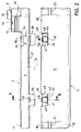
- Fig. 2 shows the two housing parts 2 and 3 in an assembly position before assembly in the direction of arrow P.
- the latches 31 and 32 formed on the side wall 6 engage with openings 33 and 34, which in on the side wall 4 of the housing part 2 molded tabs 35 and 36 are formed.
- the opening 34 is larger than the opening 33 due to an additional function, which will be described below.
- 37 and 38 each designate a fold formed on the housing part 2 or 3 in question, which fold on the housing part 2 only by the Tabs 35, 36 is interrupted on the housing part 3 by the latch 31, 32.
- the bolts 31 and 32 are free through recesses 39 and 40 in the side wall 6 such that the bolts 31 and 32 on both sides for their resilience slots 41, 42, 43 and 44 and overextensions of the Bolts 31 and 32 avoiding guide webs 45, 46, 47 and 48 are formed when the housing parts 2 and 3 are joined together.
- the reference numerals 49 and 50 denote the locking lugs interacting with the openings 33, 34 in the tabs 35 and 36.
- the enlarged opening 34 provided in the side wall 4 leads to a chamber 51 into which a seal 52 can be inserted.
- FIG. 5 The sections Fig. 3 and Fig. 4 and the top view Fig. 5 make it clear that the elements of one of the bolt connections 28, 29, 30, as it were, formed within the cross section of the relatively thin side walls of the housing parts 2 and 3 and thus a side wall of the installation housing 1 are.
- the used, frame-shaped seal 52 is provided with a suitably cut-out wall 53 and provided with a predetermined breaking point for the frame, which covers the opening 34 when the seal 52 is set.
- a plate 54 which is also formed on the frame of the seal 52 by means of a film hinge, serves as a latch. When the seal 52 is pushed into the chamber 51, the plate 54 engages behind a nose 55 provided on the housing part 2 and can therefore only be released by pressing in the wall 53.
Abstract
Description
Die Erfindung betrifft eine Anordnung zum Verbinden zweier Gehäuseteile eines Einbaugehäuses mit umlaufenden Seitenwänden, die stirnseitig zusammengefügt werden.The invention relates to an arrangement for connecting two housing parts of a built-in housing with circumferential side walls which are joined together at the end.
In den Fällen, in denen Gehäuse beispielsweise von Anzeige- und Registriergeräten lediglich eine Schutzfunktion gegen Verschmutzung und Berührung erfüllen sollen und eine tragende Funktion nur insoweit vorgesehen ist, als in dem Gehäuse die Funktionselemente des Gerätes als funktionsfertige und selbsttragende Aggregate auf einem Boden oder auf bodenständigen Säulen befestigt werden, können die Festigkeitsanforderungen verringert und relativ dünne Wandstärken in Kauf genommen werden.In cases where the housing of display and recording devices, for example, is only supposed to perform a protective function against contamination and contact and a load-bearing function is only provided to the extent that the functional elements of the device are in the housing as functional and self-supporting units on a floor or on floor-level Columns are fixed, the strength requirements can be reduced and relatively thin wall thicknesses can be accepted.
Insbesondere bei Einbaugeräten, bei denen es darauf ankommt, eine tragende Verbindung zwischen den Funktionsaggregaten innerhalb des Gehäuses und den Vorkehrungen zur Befestigung des Gehäuses am Einbauort zu schaffen, können die nicht im Kraftfluß liegenden Gehäusebereiche zweier Gehäuseschalen bzw. eines mit einer Haube oder einem Rahmen versehenen Bodens sehr einfach und dünnwandig gestaltet werden, was bei spritzgießtechnisch hergestellten Kunststoffgehäusen zu erheblich verringerten Werkzeug- und Materialkosten führt und die Standzeiten der Spritzgußformen erhöht.Especially in built-in devices where it is important to create a load-bearing connection between the functional units within the housing and the arrangements for fastening the housing at the installation location, the housing areas that are not in the power flow can be two housing shells or one with a hood or a frame Bottom are designed very simple and thin-walled, which leads to significantly reduced tool and material costs in injection molded plastic housings and increases the service life of the injection molds.
Um trotz Materialeinsparung und Dünnwandigkeit der Gehäuseteile eine ausreichende Steifigkeit der Seitenwände zu erhalten, ist es zweckmäßig, hohe Seitenwände zu vermeiden, die Seitenwände auf zwei Gehäuseteile zu verteilen und stumpf- bzw. stirnseitig zusammenzufügen. Dabei ist es nicht nur aus ästhetischen Gründen sondern auch wegen des Einbaus des Gerätes beispielsweise in eine Instrumentenkonsole eines Kraftfahrzeuges von Vorteil, daß die Seitenwände bündig zusammengefügt sind. Selbstverständlich müssen auch die Verbindungstechnik und die Verbindungsmittel für die lösbar miteinander verbindbaren Gehäuseteile der Forderung nach Serienmontage, nach Materialeinsparung und formtechnischer Einfachheit entsprechen.In order to obtain sufficient rigidity of the side walls despite the material savings and the thin walls of the housing parts, it is advisable to avoid high side walls, to distribute the side walls over two housing parts and to join them on the butt or front side. It is advantageous not only for aesthetic reasons but also because of the installation of the device, for example in an instrument panel of a motor vehicle, that the side walls are joined flush. Of course, the connection technology and the Connection means for the detachably interconnectable housing parts meet the requirement for series assembly, material savings and simplicity in terms of shape.
Die Aufgabe der vorliegenden Erfindung besteht somit darin, Verbindungsmittel für das geschilderte Gehäusekonzept zu schaffen, die den vorstehend genannten Forderungen gerecht werden, unmittelbar an den Gehäuseteilen ausgebildet sind und hohe Funktionssicherheit auch bei erheblichen thermischen und schwingungsbedingten mechanischen Belastungen bieten.The object of the present invention is therefore to provide connecting means for the housing concept described, which meet the requirements mentioned above, are formed directly on the housing parts and offer high functional reliability even with considerable thermal and vibration-related mechanical loads.
Die Lösung der Aufgabe sieht vor, daß an den Seitenwänden Riegel und den Riegeln zugeordnete Freisparungen derart ausgebildet sind, daß die den Riegelnasen abgekehrten Rückenflächen der Riegel mit den Innenflächen der Seitenwände eines Gehäuseteils im wesentlichen bündig sind und daß sich in dem anderen Gehäuseteil den Riegeln zugeordnete Bereiche geringerer Wandstärke mit für die Riegelnasen vorgesehenen Durchbrüchen befinden.The solution to the problem provides that latches and latches assigned to the latches are designed on the side walls such that the back surfaces of the latch facing away from the latch lugs are essentially flush with the inner surfaces of the side walls of a housing part and that the latches are assigned in the other housing part Areas of reduced wall thickness with openings provided for the locking lugs.
Ein bevorzugtes Ausführungsbeispiel ist dadurch gekennzeichnet, daß die Riegel durch an der Außenseite des betreffenden Gehäuseteils angebrachte Aussparungen freigestellt sind und daß an dem anderen Gehäuseteil bündig mit der Außenfläche der jeweiligen Seitenwand den Aussparungen entsprechende Lappen mit den Riegelnasen zugeordneten Durchbrüchen angeformt sind, ferner dadurch daß die Seitenwände jeweils mit einem Falz versehen sind, derart daß der Falz an dem einen Gehäuseteil auf der Seite der Riegel, an dem anderen Gehäuseteil auf der Seite der Lappen ausgebildet ist.A preferred embodiment is characterized in that the latches are released by recesses provided on the outside of the relevant housing part and in that on the other housing part, tabs corresponding to the recesses are formed flush with the outer surface of the respective side wall, with openings associated with the latch lugs, further characterized in that the Side walls are each provided with a fold, such that the fold is formed on one housing part on the latch side and on the other housing part on the tab side.
Die Erfindung bietet den Vorteil, daß eine schraubenlose, von außen lösbare Verbindung für zwei Gehäuseteile mit innen und außen bündigen Seitenwandflächen gechaffen werden kann. Damit wird die erfindungsgemäße Lösung nicht nur ästhetischen Belangen und der Forderung einer problemlosen Einbaufähigkeit gerecht, sondern sie stellt eine formtechnische Optimierung dar. Die Gehäuseteile und die Mittel zum Verbinden der Gehäuseteile erfordern keine seitlich überstehenden Konturen, insbesondere keine nach innen abstehenden Konturen, die Hinterschnitte erforderlich machen, d. h. sie lassen sich auf besonders einfache Weise entformen, mit dem Ergebnis, daß der Werkzeugaufwand gering ist.The invention offers the advantage that a screwless, externally detachable connection for two housing parts with inside and outside flush side wall surfaces can be created. Thus, the solution according to the invention not only meets aesthetic requirements and the requirement for problem-free installation, but also represents an optimization in terms of shape Housing parts and the means for connecting the housing parts do not require any laterally protruding contours, in particular no inwardly protruding contours that require undercuts, ie they can be demolded in a particularly simple manner, with the result that the tooling is low.
Die Erfindung mit sozusagen innerhalb des Querschnitts einer Wand ausgebildeten Verbindungs- bzw. Verriegelungsmitteln gestattet ferner, daß ohne Mehraufwand mehrere Riegelverbindungen an ein und derselben Wand ausgebildet werden können und somit unter Beibehaltung der bereits genannten Vorzüge ein mehrfaches "Zusammenheften" zweier Seitenwände von Gehäuseteilen ermöglicht wird, was sich insbesondere bei den angestrebten dünnen Gehäusewänden, die sich unter thermischer Beanspruchung leicht wölben und dabei auseinanderbiegen können, besonders vorteilhaft auswirkt. In diesem Sinne ist aber auch das gegenseitige Übergreifen der Riegelverbindungen und der Falzverbindung wirksam, d. h. auf die Gehäusewände seitlich einwirkende Kräfte werden über die Verbindungsmittel auf beide Gehäuseteile verteilt und ein Auseinanderklaffen der miteinander verbundenen Gehäuseteile wird vermieden.The invention, so to speak, within the cross-section of a wall formed connecting or locking means also allows that several bolt connections can be formed on the same wall without additional effort and thus a multiple "tacking" two side walls of housing parts is possible while maintaining the advantages mentioned above , which has a particularly advantageous effect, particularly in the case of the thin housing walls which are aimed at and which curve slightly under thermal stress and can thereby bend apart. In this sense, however, the mutual overlap of the bolt connections and the fold connection is effective, d. H. Forces acting laterally on the housing walls are distributed to both housing parts via the connecting means and a gaping apart of the connected housing parts is avoided.
Die glattflächige Ausbildung der Seitenwände des Gehäuses gestattet einen exakt rechteckigen oder quadratischen Einbauquerschnitt des Gehäuses, wobei die rechtwinklig zueinander stehenden Seitenwände der Gehäuseteile nicht unmittelbar aufeinanderstoßend ausgebildet sind sondern Wandverbindungen, beispielsweise sickenförmige, nach innen gewölbte Wandteile, vorgesehen sind, die die Gehäuseecken freisparen. Diese Ausführungsform bietet den Vorteil, daß vorzugsweise an dem Gehäuseteil, das die Funktionsaggregate trägt, noch innerhalb des Einbauquerschnitts Konsolen zur Befestigung des Gehäuses ausgebildet werden können. Selbstverständlich lassen sich die Konsolen auch innerhalb der Seitenwände, beispielsweise auch an zwei gegenüberliegenden Seitenwänden, durch geeignete Einbuchtungen ausbilden. Dadurch würde zwar zusätzlich eine höhere Steifigkeit der betreffenden Seitenwände erreicht, der innerhalb des Gerätes zur Verfügung stehende Raum aber verringert.The smooth surface design of the side walls of the housing permits a precisely rectangular or square installation cross section of the housing, the side walls of the housing parts which are at right angles to one another not being directly abutting but wall connections, for example bead-shaped, inwardly curved wall parts, which save the corners of the housing. This embodiment offers the advantage that, preferably on the housing part which carries the functional units, brackets for fastening the housing can still be formed within the installation cross section. Of course, the brackets can also be formed within the side walls, for example also on two opposite side walls, by suitable indentations. Thereby a higher rigidity of the relevant side walls would be achieved, but the space available within the device would be reduced.
Im folgenden sei die Erfindung anhand der beigefügten Zeichnungen näher erläutert.The invention is explained in more detail below with reference to the accompanying drawings.
Es zeigen
- Fig. 1 eine Perspektivdarstellung des erfindungsgemäßen Einbaugehäuses,
- Fig. 2 Seitenansichten der beiden das Einbaugehäuse bildenden Gehäuseteile in einer Montagestellung unmittelbar vor dem Zusammenfügen,
- Fig. 3 einen Schnitt durch einen am einen Gehäuseteil angeformten Lappen gemäß der Schnittlinie A in Fig. 2,
- Fig. 4 einen Schnitt durch einen am anderen Gehäuseteil angeformten Riegel gemäß der Schnittlinie B in Fig. 2,
- Fig. 5 eine Draufsicht auf einen an einer Seitenwand ausgebildeten Riegel gemäß der Pfeilrichtung D in Fig. 2,
- Fig. 6 einen Schnitt durch eine plombierte Riegelverbindung gemäß der Schnittlinie c in Fig. 1 und
- Fig. 7 eine Draufsicht auf das Einbaugehäuse.
- 1 is a perspective view of the installation housing according to the invention,
- 2 side views of the two housing parts forming the installation housing in an assembly position immediately before assembly,
- 3 shows a section through a tab formed on a housing part according to section line A in FIG. 2,
- 4 shows a section through a bolt formed on the other housing part according to section line B in FIG. 2,
- 5 is a plan view of a latch formed on a side wall in the direction of arrow D in FIG. 2,
- Fig. 6 shows a section through a sealed bolt connection according to section line c in Fig. 1 and
- Fig. 7 is a plan view of the installation housing.
Die Fig. 1 zeigt ein Einbaugehäuse 1 bestehend aus zwei Gehäusebauteilen 2 und 3 mit umlaufenden Seitenwänden, von denen in Fig. 1 jeweils zwei, 4 und 5 bzw. 6 und 7, sichtbar sind. Das eine Gehäuseteil 3 dient bei dem dargestellten Einbaugehäuse 1 der Aufnahme von Funktionsaggregaten des betreffenden Gerätes, in diesem Falle eines Registriergerätes, das andere Gehäuseteil 2 stellt eine Abdeckung dar, an welcher ein Podest 8 ausgebildet ist, das beim Einbau des Gerätes beispielsweise in ein Armaturenbrett eines Kraftfahrzeugs in eine Aussparung des Armaturenbretts von der Rückseite her eingreift und durch eine nicht dargestellte Frontblende, mit der Anpassungen an die Gestaltung des Armaturenbretts vorgenommen werden können, abdeckbar ist. Zur Halterung der Frontblende an dem Gehäuseteil 2 dienen Ausschnitte 9 und 10, Kerben 11 und 12 sowie Einschnitte 13 und 14. Ein Schlitz 15 ist für die Eingabe und Ausgabe der verwendeten Registrier- bzw. Druckträger vorgesehen. Mit 16 ist im Falle einer Einfachstausführung des Gerätes eine Taste bezeichnet, mittels der die Ausgabe eines Druckträgers steuerbar ist. Selbstverständlich kann je nach Einbausituation das Gehäuseteil 2 in anderer Weise gestaltet, beispielsweise rahmenförmig ausgebildet sein. Auch kann das Gerät zusätzlich mit einer Anzeige ausgerüstet sein oder ausschließlich ein Anzeigegerät darstellen, wobei in dem abdeckenden Gehäuseteil 2 ein geeigneter Ausschnitt vorgesehen sein muß.1 shows a built-in housing 1 consisting of two
Wie ferner aus Fig. 1 ersichtlich ist, sind an beiden Gehäuseteilen 2 und 3 im Eckbereich der Seitenwände Einbuchtungen vorgesehen, von denen stellvertretend für die übrigen die einer Ecke des Einbaugehäuses 1 zugeordneten mit 17, 18 und 19 bezeichnet sind. Die Einbuchtungen 18 und 19 sparen an dem die Funktionsaggregate des Gerätes aufnehmenden Gehäuseteil 3 Konsolen aus, die mit 20, 21, 22 und 23 bezeichnet sind. In den Konsolen vorgesehene Bohrungen 24, 25, 26 und 27 dienen dem Durchführen von Befestigungsschrauben oder ortsfesten Gewindestiften.As can also be seen from FIG. 1, indentations are provided on both
Wie aus der Draufsicht Fig. 7 ersichtlich ist, liegen die Konsolen 20, 21, 22, 23 innerhalb rechteckiger oder quadratischer Querschnittskonturen des Einbaugehäuses 1, dessen glattflächige Seitenwände durch die bündig aneinander stoßenden Seitenwände 4 und 6, 5 und 7 sowie diesen gegenüberliegenden, jedoch nicht bezeichneten Seitenwänden der Gehäuseteile 2 und 3 gebildet sind. Mit 28, 29 und 30 sind in Fig. 1 Riegelverbindungen bezeichnet, mit denen die Gehäuseteile 2 und 3 von außen lösbar miteinander verbunden sind. Erfindungsgemäß sind die Riegelverbindungen derart gestaltet, daß ihre Elemente weder außen, noch innen von den Seitenwänden des Einbaugehäuses 1 abstehen.As can be seen from the top view in FIG. 7, the
Im folgenden werden die den beiden Seitenwänden 4 und 6 zugeordneten Riegelverbindungen näher beschrieben. Selbstverständlich sind zum Befestigen der Gehäuseteile 2 und 3 auch an den nicht in Ansicht dargestellten Seitenwänden Riegelverbindungen vorgesehen. Bei relativ langen Seitenwänden sind auch mehr als zwei Riegelverbindungen denkbar.The latch connections assigned to the two
Die Fig. 2 zeigt die beiden Gehäuseteile 2 und 3 in einer Montagestellung vor dem Zusammenfügen in Pfeilrichtung P. Beim Zusammenfügen gehen die an der Seitenwand 6 ausgebildeten Riegel 31 und 32 in Eingriff mit Durchbrüchen 33 und 34, die in an der Seitenwand 4 des Gehäuseteils 2 angeformten Lappen 35 und 36 ausgebildet sind. Der Durchbruch 34 ist aufgrund einer zusätzlichen Funktion, die im folgenden noch beschrieben wird, größer ausgebildet als der Durchbruch 33. Mit 37 und 38 ist jeweils ein an dem betreffenden Gehäuseteil 2 bzw. 3 umlaufend ausgebildeter Falz bezeichnet, der am Gehäuseteil 2 lediglich durch die Lappen 35, 36, am Gehäuseteil 3 durch die Riegel 31, 32 unterbrochen ist.Fig. 2 shows the two
Wie ferner aus der Fig. 2 ersichtlich ist, sind die Riegel 31 und 32 durch Aussparungen 39 und 40 in der Seitenwand 6 derart freigestellt, daß beidseitig der Riegel 31 und 32 für deren Federungsfähigkeit erforderliche Schlitze 41, 42, 43 und 44 sowie Überdehnungen der Riegel 31 und 32 beim Zusammenfügen der Gehäuseteile 2 und 3 vermeidende Führungsstege 45, 46, 47 und 48 ausgebildet sind. Die Bezugszeichen 49 und 50 bezeichnen die mit den Durchbrüchen 33, 34 in den Lappen 35 und 36 zusammenwirkenden Riegelnasen. Der in der Seitenwand 4 vorgesehene, vergrößerte Durchbruch 34 führt zu einer Kammer 51, in die eine Plombe 52 einsetzbar ist.As can also be seen from Fig. 2, the
Die Schnitte Fig. 3 und Fig. 4 sowie die Draufsicht Fig. 5 machen deutlich, daß die Elemente einer der Riegelverbindungen 28, 29, 30 sozusagen innerhalb des Querschnitts der relativ dünnen Seitenwände der Gehäuseteile 2 und 3 und somit einer Seitenwand des Einbaugehäuses 1 ausgebildet sind. Die Draufsicht Fig. 5 zeigt in Verbindung mit Fig. 2 anschaulich das gegenseitige Zusammenfügen von Lappen und Führungsstegen einerseits und der Falzverbindung andererseits.The sections Fig. 3 and Fig. 4 and the top view Fig. 5 make it clear that the elements of one of the
Mit der Fig. 6 ist eine Lösung dargestellt, die es gestattet, eine der erfindungsgemäßen Riegelverbindungen und somit das Gerät zu plombieren. Die verwendete, rahmenförmig ausgebildete Plombe 52 ist mit einer in geeigneter Weise freigesparten und mit einer Sollbruchstelle zum Rahmen versehenen Wand 53 ausgerüstet, die den Durchbruch 34, wenn die Plombe 52 gesetzt ist, abdeckt. Eine ebenfalls mittels eines Filmscharniers an dem Rahmen der Plombe 52 angeformte Platte 54 dient als Rastklinke. Beim Einschieben der Plombe 52 in die Kammer 51 rastet die Platte 54 hinter einer am Gehäuseteil 2 vorgesehenen Nase 55 ein und ist somit nur noch durch Eindrücken der Wand 53 lösbar.6 shows a solution that it allowed to seal one of the bolt connections according to the invention and thus the device. The used, frame-
Der Vollständigkeit halber sei noch erwähnt, daß für eine Verwendung, bei der eine Lösbarkeit der Riegelverbindungen nicht zwingend erforderlich ist, anstelle der den Riegelnasen zugeordneten Durchbrüche von außen unzugängliche Aussparungen vorgesehen sein können. Es ist ferner denkbar, die Riegel über die durch den Rand des betreffenden Gehäuseteils gebildete Ebene hinausragen zu lassen und in der Seitenwand des anderen Gehäuseteils geeignete Aussparungen vorzusehen oder die Überstände von Lappen und Riegeln gleichmäßig auf beide Gehäuseteile zu verteilen.For the sake of completeness, it should also be mentioned that for a use in which a releasability of the bolt connections is not absolutely necessary, instead of the openings assigned to the bolt lugs, inaccessible recesses can be provided from the outside. It is also conceivable to let the bolts protrude beyond the plane formed by the edge of the housing part in question and to provide suitable cutouts in the side wall of the other housing part or to evenly distribute the protrusions of tabs and bolts over both housing parts.
Claims (7)
dadurch gekennzeichnet,
daß an den Seitenwänden Riegel und den Riegeln zugeordnete Freisparungen derart ausgebildet sind, daß die den Riegelnasen abgekehrten Rückenflächen der Riegel mit den Innenflächen der Seitenwände eines Gehäuseteils (3) im wesentlichen bündig sind und
daß sich in dem anderen Gehäuseteil (2) den Riegeln zugeordnete Bereiche geringerer Wandstärke mit für die Riegelnasen vorgesehenen Durchbrüchen befinden.Arrangement for connecting two housing parts of a built-in housing with circumferential side walls which are joined on the end face
characterized,
that bars and cutouts assigned to the bars on the side walls are designed such that the back surfaces of the bars facing away from the bar lugs are essentially flush with the inner surfaces of the side walls of a housing part (3) and
that there are in the other housing part (2) associated areas of reduced wall thickness with openings provided for the locking tabs.
dadurch gekennzeichnet,
daß die Riegel (31, 32) durch an der Außenseite des betreffenden Gehäuseteils (3) angebrachte Aussparungen (39, 40) freigestellt sind und
daß an dem anderen Gehäuseteil (2) bündig mit der Außenfläche der jeweiligen Seitenwand (4) den Aussparungen (39, 40) entsprechende Lappen (35, 36) mit den Riegelnasen (49, 50) zugeordneten Durchbrüchen (33, 34) angeformt sind.Arrangement according to claim 1,
characterized,
that the bolts (31, 32) are free through cutouts (39, 40) provided on the outside of the relevant housing part (3) and
that on the other housing part (2) flush with the outer surface of the respective side wall (4) the recesses (39, 40) corresponding tabs (35, 36) with the locking lugs (49, 50) associated openings (33, 34) are formed.
dadurch gekennzeichnet,
daß die Riegel (31, 32) unterhalb einer durch den äußeren Rand der Seitenwände (6, 7) bestimmten Ebene ausgebildet sind.Arrangement according to claim 1,
characterized,
that the bars (31, 32) are formed below a plane determined by the outer edge of the side walls (6, 7).
dadurch gekennzeichnet,
daß die Tiefe der Aussparungen (39, 40) quer zur Seitenwand (6) durch beiderseits der Riegel (31, 32) ausgebildete und mit der Innenfläche der Seitenwand (6) bündige Führungsstege (45, 46, 47, 48) begrenzt ist.Arrangement according to claim 2,
characterized,
that the depth of the recesses (39, 40) transverse to the side wall (6) is formed by guide bars (45, 46, 47, 48) which are formed on both sides of the bars (31, 32) and are flush with the inner surface of the side wall (6).
dadurch gekennzeichnet,
daß die Seitenwände (4, 5, 6, 7) jeweils mit einem Falz (37, 38) versehen sind, derart daß der Falz (38) an dem einen Gehäuseteil (3) auf der Seite der Riegel (31, 32), an dem anderen Gehäuseteil (2) auf der Seite der Lappen (35, 36) ausgebildet ist.Arrangement according to claim 1,
characterized,
that the side walls (4, 5, 6, 7) are each provided with a fold (37, 38), so that the fold (38) on the one housing part (3) on the side of the latch (31, 32) the other housing part (2) on the side of the tabs (35, 36) is formed.
dadurch gekennzeichnet,
daß wenigstens einem Riegel (32) des Einbaugehäuses (1) eine den Riegel (32) hintergreifende und mit dem Einbaugehäuse (1) rastend verbindbare Plombe (52) zugeordnet ist.Arrangement according to claim 1,
characterized,
that at least one bolt (32) of the installation housing (1) is assigned a seal (52) which engages behind the bolt (32) and can be latched to the installation housing (1).
dadurch gekennzeichnet,
daß an den Seitenwänden (4, 5, 6, 7) der Gehäuseteile (2, 3) Einbuchtungen (17, 18, 19) vorgesehen sind und
daß an einem Gehäuseteil (3) zwischen den Einbuchtungen (18, 19) Konsolen (20, 21, 22, 23) mit der Befestigung des Einbaugehäuses (1) dienenden Bohrungen (24, 25, 26, 27) ausgebildet sind.Installation housing according to claim 1,
characterized,
that on the side walls (4, 5, 6, 7) of the housing parts (2, 3) indentations (17, 18, 19) are provided and
that on a housing part (3) between the indentations (18, 19) brackets (20, 21, 22, 23) with the attachment of the installation housing (1) serving bores (24, 25, 26, 27) are formed.
Applications Claiming Priority (2)
| Application Number | Priority Date | Filing Date | Title |
|---|---|---|---|
| DE9017103U DE9017103U1 (en) | 1990-12-19 | 1990-12-19 | |
| DE9017103U | 1990-12-19 |
Publications (2)
| Publication Number | Publication Date |
|---|---|
| EP0491270A2 true EP0491270A2 (en) | 1992-06-24 |
| EP0491270A3 EP0491270A3 (en) | 1993-08-04 |
Family
ID=6860417
Family Applications (1)
| Application Number | Title | Priority Date | Filing Date |
|---|---|---|---|
| EP19910121215 Withdrawn EP0491270A3 (en) | 1990-12-19 | 1991-12-11 | Fixture for assembling two parts of a case |
Country Status (3)
| Country | Link |
|---|---|
| EP (1) | EP0491270A3 (en) |
| JP (1) | JPH0746171Y2 (en) |
| DE (1) | DE9017103U1 (en) |
Cited By (8)
| Publication number | Priority date | Publication date | Assignee | Title |
|---|---|---|---|---|
| EP0604138A1 (en) * | 1992-12-25 | 1994-06-29 | Omron Corporation | Control device |
| WO1998022721A1 (en) * | 1996-11-21 | 1998-05-28 | Philips Electronics N.V. | Detachable connection between two housing sections |
| EP1111976A1 (en) * | 1999-12-21 | 2001-06-27 | Nokia Mobile Phones Ltd. | Window clipping arrangement |
| WO2004036970A1 (en) * | 2002-10-11 | 2004-04-29 | Hirschmann Electronics Gmbh & Co. Kg | Housing for antenna amplifier |
| EP1657554A1 (en) * | 2004-11-05 | 2006-05-17 | EMH Elektrizitätszähler GmbH & Co KG | Electronic electricity meter |
| ES2330984A1 (en) * | 2007-03-29 | 2009-12-17 | M. Del Mar Guell Ferrer | Box-case for automated control panels (Machine-translation by Google Translate, not legally binding) |
| CN103922043A (en) * | 2014-05-04 | 2014-07-16 | 苏州博讯仪器有限公司 | Portable instrument box |
| DE19856335B4 (en) * | 1998-12-07 | 2017-03-09 | Robert Bosch Gmbh | Junction box |
Families Citing this family (11)
| Publication number | Priority date | Publication date | Assignee | Title |
|---|---|---|---|---|
| DE4210526A1 (en) * | 1991-04-25 | 1992-10-29 | Abb Patent Gmbh | Data transfer arrangement between measurement acquisition and processing units - has auxiliary unit mechanically joined to acquisition unit and coupled to it which passes data to processing unit |
| DE4133169A1 (en) * | 1991-10-07 | 1993-04-08 | Abb Patent Gmbh | Electrical connection module for switchgear installation - has main block into which spring contact elements are set to couple with screw terminals or flat contacts |
| US5233506A (en) * | 1992-02-21 | 1993-08-03 | Motorola, Inc. | Fastener for housing assembly |
| DE9209557U1 (en) * | 1992-07-16 | 1992-09-17 | Odenwaelder Kunststoffwerke Gmbh & Co Gehaeusesysteme Kg, 6967 Buchen, De | |
| DE4431281A1 (en) * | 1994-09-02 | 1996-03-07 | Teves Gmbh Alfred | Snap connection of housing parts with integrated locking pin |
| DE19712239C1 (en) * | 1997-03-24 | 1998-08-27 | Siemens Ag | Electrical device housing, in particular for a consumption meter |
| DE19919466C2 (en) * | 1999-04-29 | 2001-03-22 | Thyssenkrupp Stahl Ag | Two-part housing |
| JP4400133B2 (en) * | 2003-07-28 | 2010-01-20 | 株式会社デンソー | Assembly structure of container and lid member |
| DE102014220169A1 (en) * | 2014-05-30 | 2015-12-03 | Power Plus Communications Ag | Housing for electrical modules for mounting on a carrier rail and housing arrangement |
| DE202017001434U1 (en) * | 2017-03-17 | 2018-06-20 | Heinen Elektronik Gmbh | Housing for a plug-in contact element for the tap-proof supply of an IT component with electrical energy and plug contact |
| DE202018103694U1 (en) * | 2018-06-28 | 2019-10-09 | steute Schaltgeräte GmbH & Co. KG | Housing with a locking arrangement of a housing cover |
Citations (8)
| Publication number | Priority date | Publication date | Assignee | Title |
|---|---|---|---|---|
| FR1052430A (en) * | 1952-03-14 | 1954-01-25 | App Blinde Sa D | Box for switch, inverter, circuit breaker or other |
| DE2815526B1 (en) * | 1978-04-11 | 1979-07-19 | Standard Elek K Lorenz Ag | Openable housing |
| US4344646A (en) * | 1980-05-27 | 1982-08-17 | Woodstream Corporation | Detachable latch |
| DE3346243A1 (en) * | 1983-12-21 | 1985-07-11 | Siemens AG, 1000 Berlin und 8000 München | Snap connection between two elements |
| DE8521954U1 (en) * | 1985-07-30 | 1985-09-19 | Siemens AG, 1000 Berlin und 8000 München | Housing for accommodating a circuit arrangement |
| US4759466A (en) * | 1986-08-14 | 1988-07-26 | Apple Computer, Inc. | EMI seam for enclosures |
| US4801039A (en) * | 1988-02-11 | 1989-01-31 | Netra Plastics | Animal proof container |
| EP0368693A1 (en) * | 1988-10-24 | 1990-05-16 | Gefitec S.A. | Box-suitcase to store various items, in particular do-it-yourself hardware |
Family Cites Families (12)
| Publication number | Priority date | Publication date | Assignee | Title |
|---|---|---|---|---|
| FR1064166A (en) * | 1951-12-14 | 1954-05-11 | Travel kit | |
| JPS5032310U (en) * | 1973-07-18 | 1975-04-09 | ||
| DE2719389B2 (en) * | 1977-04-30 | 1980-07-17 | Hartmann & Braun Ag, 6000 Frankfurt | Cases for measuring instruments |
| NL7811894A (en) * | 1978-12-06 | 1980-06-10 | Brabantia Leasing Factoring | DEVICE FOR STORING DOCUMENTS, VALUE PAPERS, VALUABLE ITEMS AND THE LIKE. |
| DE3004271C2 (en) * | 1980-02-06 | 1984-10-11 | Büchele, Karl, 8000 München | Housing composed of modular elements |
| DE8020040U1 (en) * | 1980-07-25 | 1980-10-23 | Siemens Ag, 1000 Berlin Und 8000 Muenchen | Installation device for surface mounting |
| FR2544158A1 (en) * | 1983-04-08 | 1984-10-12 | Gavilan Computer Corp | ASSEMBLY DEVICE FOR COMPUTER SYSTEM |
| JPS6082074U (en) * | 1983-11-10 | 1985-06-06 | 三菱電機株式会社 | Fixed locking device for cases, etc. |
| DE3610613A1 (en) * | 1986-03-29 | 1987-10-01 | Gossen Gmbh | Measuring instrument housing |
| JPH01177523U (en) * | 1988-05-26 | 1989-12-19 | ||
| DE3933644A1 (en) * | 1989-10-08 | 1991-04-11 | Asea Brown Boveri | Electrical measuring appts. housing - formed by 2 identical half shells locked together along abutting edges of sidewalls without using screws |
| DE9000470U1 (en) * | 1990-01-17 | 1990-05-03 | Geze Gmbh & Co, 7250 Leonberg, De |
-
1990
- 1990-12-19 DE DE9017103U patent/DE9017103U1/de not_active Expired - Lifetime
-
1991
- 1991-12-11 EP EP19910121215 patent/EP0491270A3/en not_active Withdrawn
- 1991-12-18 JP JP1991104365U patent/JPH0746171Y2/en not_active Expired - Fee Related
Patent Citations (8)
| Publication number | Priority date | Publication date | Assignee | Title |
|---|---|---|---|---|
| FR1052430A (en) * | 1952-03-14 | 1954-01-25 | App Blinde Sa D | Box for switch, inverter, circuit breaker or other |
| DE2815526B1 (en) * | 1978-04-11 | 1979-07-19 | Standard Elek K Lorenz Ag | Openable housing |
| US4344646A (en) * | 1980-05-27 | 1982-08-17 | Woodstream Corporation | Detachable latch |
| DE3346243A1 (en) * | 1983-12-21 | 1985-07-11 | Siemens AG, 1000 Berlin und 8000 München | Snap connection between two elements |
| DE8521954U1 (en) * | 1985-07-30 | 1985-09-19 | Siemens AG, 1000 Berlin und 8000 München | Housing for accommodating a circuit arrangement |
| US4759466A (en) * | 1986-08-14 | 1988-07-26 | Apple Computer, Inc. | EMI seam for enclosures |
| US4801039A (en) * | 1988-02-11 | 1989-01-31 | Netra Plastics | Animal proof container |
| EP0368693A1 (en) * | 1988-10-24 | 1990-05-16 | Gefitec S.A. | Box-suitcase to store various items, in particular do-it-yourself hardware |
Cited By (14)
| Publication number | Priority date | Publication date | Assignee | Title |
|---|---|---|---|---|
| EP0716564A2 (en) * | 1992-12-25 | 1996-06-12 | Omron Corporation | Control device |
| EP0716564A3 (en) * | 1992-12-25 | 1997-03-26 | Omron Tateisi Electronics Co | Control device |
| US5631673A (en) * | 1992-12-25 | 1997-05-20 | Omron Corporation | Control device |
| EP0604138A1 (en) * | 1992-12-25 | 1994-06-29 | Omron Corporation | Control device |
| WO1998022721A1 (en) * | 1996-11-21 | 1998-05-28 | Philips Electronics N.V. | Detachable connection between two housing sections |
| US5931514A (en) * | 1996-11-21 | 1999-08-03 | U.S. Philips Corporation | Detachable connection between two housing sections |
| DE19856335B4 (en) * | 1998-12-07 | 2017-03-09 | Robert Bosch Gmbh | Junction box |
| EP1111976A1 (en) * | 1999-12-21 | 2001-06-27 | Nokia Mobile Phones Ltd. | Window clipping arrangement |
| US6842633B1 (en) | 1999-12-21 | 2005-01-11 | Nokia Mobile Phones Ltd. | Clip arrangement for portable electronic apparatus housing assembly |
| US7189919B2 (en) | 2002-10-11 | 2007-03-13 | Hirschmann Electronics Gmbh & Co. Kg | Housing for antenna amplifier |
| WO2004036970A1 (en) * | 2002-10-11 | 2004-04-29 | Hirschmann Electronics Gmbh & Co. Kg | Housing for antenna amplifier |
| EP1657554A1 (en) * | 2004-11-05 | 2006-05-17 | EMH Elektrizitätszähler GmbH & Co KG | Electronic electricity meter |
| ES2330984A1 (en) * | 2007-03-29 | 2009-12-17 | M. Del Mar Guell Ferrer | Box-case for automated control panels (Machine-translation by Google Translate, not legally binding) |
| CN103922043A (en) * | 2014-05-04 | 2014-07-16 | 苏州博讯仪器有限公司 | Portable instrument box |
Also Published As
| Publication number | Publication date |
|---|---|
| DE9017103U1 (en) | 1991-03-07 |
| EP0491270A3 (en) | 1993-08-04 |
| JPH0746171Y2 (en) | 1995-10-25 |
| JPH0496217U (en) | 1992-08-20 |
Similar Documents
| Publication | Publication Date | Title |
|---|---|---|
| EP0491270A2 (en) | Fixture for assembling two parts of a case | |
| EP3103168B1 (en) | Profile of a framework for an electrical or distribution cabinet | |
| EP1511368B1 (en) | Sandwich housing for antenna amplifier | |
| DE3631772A1 (en) | HOUSING FOR BOARDING BOARD | |
| WO1996014729A1 (en) | Switchgear cabinet with frame | |
| EP0939984A1 (en) | Switching cabinet | |
| EP0789944A1 (en) | Frame for a switchgear cabinet | |
| EP0939986B1 (en) | Switching cabinet with a rack | |
| DE3710567C1 (en) | Base for a control cabinet | |
| DE102006040358A1 (en) | Built-in refrigeration unit with output device | |
| DE2251410A1 (en) | FRAME CONSTRUCTION | |
| DE4205443C1 (en) | Base for switch cabinet - comprises four corner pieces, two side panels, and front and back panels, connected together at front and rear by bolts | |
| EP0675295A1 (en) | Fixing device | |
| EP0235694B1 (en) | Fitting for an all-glass construction | |
| DE3403369A1 (en) | FASTENING ARRANGEMENT | |
| EP1962388B1 (en) | Frame for electric switches and plug sockets | |
| EP2114200B1 (en) | Control desk | |
| DE2121798C3 (en) | Built-in switch with removable cover plate | |
| EP0162232B1 (en) | Drawer front | |
| EP0910145B1 (en) | Frame for a box cover | |
| DE69831833T2 (en) | Metal cabinet for electrical appliances | |
| EP0607879A1 (en) | Casing for a electronic device | |
| DE4409155A1 (en) | Connecting element for connecting panel-like wall elements | |
| DE2939646C2 (en) | Measuring instrument housing | |
| DE102014109970B4 (en) | casing |
Legal Events
| Date | Code | Title | Description |
|---|---|---|---|
| PUAI | Public reference made under article 153(3) epc to a published international application that has entered the european phase |
Free format text: ORIGINAL CODE: 0009012 |
|
| AK | Designated contracting states |
Kind code of ref document: A2 Designated state(s): DE ES FR GB IT |
|
| PUAL | Search report despatched |
Free format text: ORIGINAL CODE: 0009013 |
|
| RAP1 | Party data changed (applicant data changed or rights of an application transferred) |
Owner name: MANNESMANN KIENZLE GMBH (HR B1220) |
|
| AK | Designated contracting states |
Kind code of ref document: A3 Designated state(s): DE ES FR GB IT |
|
| STAA | Information on the status of an ep patent application or granted ep patent |
Free format text: STATUS: THE APPLICATION IS DEEMED TO BE WITHDRAWN |
|
| 18D | Application deemed to be withdrawn |
Effective date: 19940205 |