EP1111973A2 - Kolumn-Matrixverbinder und Methode für das Verbinden eines Lötkolumn - Google Patents
Kolumn-Matrixverbinder und Methode für das Verbinden eines Lötkolumn Download PDFInfo
- Publication number
- EP1111973A2 EP1111973A2 EP00126576A EP00126576A EP1111973A2 EP 1111973 A2 EP1111973 A2 EP 1111973A2 EP 00126576 A EP00126576 A EP 00126576A EP 00126576 A EP00126576 A EP 00126576A EP 1111973 A2 EP1111973 A2 EP 1111973A2
- Authority
- EP
- European Patent Office
- Prior art keywords
- solder
- column
- columns
- length
- bores
- Prior art date
- Legal status (The legal status is an assumption and is not a legal conclusion. Google has not performed a legal analysis and makes no representation as to the accuracy of the status listed.)
- Withdrawn
Links
Images


Classifications
-
- H—ELECTRICITY
- H05—ELECTRIC TECHNIQUES NOT OTHERWISE PROVIDED FOR
- H05K—PRINTED CIRCUITS; CASINGS OR CONSTRUCTIONAL DETAILS OF ELECTRIC APPARATUS; MANUFACTURE OF ASSEMBLAGES OF ELECTRICAL COMPONENTS
- H05K3/00—Apparatus or processes for manufacturing printed circuits
- H05K3/30—Assembling printed circuits with electric components, e.g. with resistor
- H05K3/32—Assembling printed circuits with electric components, e.g. with resistor electrically connecting electric components or wires to printed circuits
- H05K3/34—Assembling printed circuits with electric components, e.g. with resistor electrically connecting electric components or wires to printed circuits by soldering
- H05K3/341—Surface mounted components
- H05K3/3421—Leaded components
- H05K3/3426—Leaded components characterised by the leads
-
- H—ELECTRICITY
- H01—ELECTRIC ELEMENTS
- H01R—ELECTRICALLY-CONDUCTIVE CONNECTIONS; STRUCTURAL ASSOCIATIONS OF A PLURALITY OF MUTUALLY-INSULATED ELECTRICAL CONNECTING ELEMENTS; COUPLING DEVICES; CURRENT COLLECTORS
- H01R43/00—Apparatus or processes specially adapted for manufacturing, assembling, maintaining, or repairing of line connectors or current collectors or for joining electric conductors
- H01R43/02—Apparatus or processes specially adapted for manufacturing, assembling, maintaining, or repairing of line connectors or current collectors or for joining electric conductors for soldered or welded connections
- H01R43/0256—Apparatus or processes specially adapted for manufacturing, assembling, maintaining, or repairing of line connectors or current collectors or for joining electric conductors for soldered or welded connections for soldering or welding connectors to a printed circuit board
-
- Y—GENERAL TAGGING OF NEW TECHNOLOGICAL DEVELOPMENTS; GENERAL TAGGING OF CROSS-SECTIONAL TECHNOLOGIES SPANNING OVER SEVERAL SECTIONS OF THE IPC; TECHNICAL SUBJECTS COVERED BY FORMER USPC CROSS-REFERENCE ART COLLECTIONS [XRACs] AND DIGESTS
- Y02—TECHNOLOGIES OR APPLICATIONS FOR MITIGATION OR ADAPTATION AGAINST CLIMATE CHANGE
- Y02P—CLIMATE CHANGE MITIGATION TECHNOLOGIES IN THE PRODUCTION OR PROCESSING OF GOODS
- Y02P70/00—Climate change mitigation technologies in the production process for final industrial or consumer products
- Y02P70/50—Manufacturing or production processes characterised by the final manufactured product
Definitions
- This invention relates generally to the field of electrical connectors, and particularly to an apparatus for establishing a mechanical and electrical connection between an electrical connector and a substrate, such as a Printed Circuit Board (PCB), and a method of attaching a column of solder to a connector terminal to form a solder column.
- a substrate such as a Printed Circuit Board (PCB)
- PCB Printed Circuit Board
- the electrical terminals of a connector may be mechanically and electrically connected to electrical contact pads on a PCB by several conventional methods, including a pin grid array (PGA), land grid array (LGA), and ball grid array (BGA).
- PGA pin grid array
- LGA land grid array
- BGA ball grid array
- the circuit industry connects packages to a substrate by any of the above methods, as well as column grid array (CGA).
- the present invention is directed at improving the reliability of the mechanical/electrical connection formed between an electrical connector and a substrate, such as a PCB.
- a Ball Grid Array (BGA) type of electrical connector typically has a plurality of solder balls that interconnect the connector to a PCB.
- a typical BGA connector consists of a substrate having an array of electrical contact pads or traces disposed about the substrate's surface.
- spherical shaped solder balls are attached to the terminals of the connector by first applying a resin flux to the electrical contact pads, positioning the solder balls onto the electrical contact pads, and running the connector through a reflow furnace. During the reflow process the solder balls are held in position by the flux and wetted onto the electrical contact pads. In addition to holding the solder balls in position, the flux promotes the wetting of the solder balls to the contact pads and chemically cleans the contact pad surfaces.
- solder portion located near the solder ball and electrical contact pad interface flows to form an electrical and mechanical connection, but in all other respects, the solder balls generally maintain their spherical shape.
- resin flux other methods are known that utilize supporting fixtures to hold the solder balls in position during reflow with or without the use of flux.
- solder balls Because of their spherical shape, they tend to form short connections that have generally short lengths which may break under stress. As a result, the electrical connection may be interrupted between the connector and the PCB.
- CCGA Ceramic Column Grid Array
- CTE coefficient of thermal expansion
- a well accepted mounting arrangement for mounting a surface mount electrical connector having terminals depending therefrom is to solder each of the metallic terminals onto a copper clad contact pad on the PCB material using a lead and tin alloy solder paste.
- the thermal profile during solder paste reflow typically exceeds 200°C for short periods of time.
- the CTE of the epoxy and glass PCB material is different than the CTE of the metallic material of the terminal and is usually also different than the CTE of the solder alloy that joins the two. Effects of this thermal mismatch are first encountered during the cool down period after the solder is reflowed during initial attachment. The molten solder will solidify just below 200°C, and at that time the assembly is mechanically fixed and as near stress free as possible.
- CCGAs include a plurality of solid solder columns that are positioned between the electrical contact pads of a package and a PCB.
- the connection between the electrical contact pads on a package and PCB are generally formed by first applying a resin flux to the electrical contact pads, positioning the solder columns over the pads, and running the unit through a reflow furnace.
- the solder column height which is greater than the diameter of a typical solder ball, allows for greater flexibility in establishing the connection between a package and a PCB. By allowing for greater flexibility, the solder columns reduce stresses at the solder column/electrical contact pad interfaces which, in turn, results in higher product reliability.
- the column addresses the relative movement between the connector and the PCB by bending as opposed to shearing.
- the present invention provides an improved apparatus and method for forming column grid arrays which solve the aforementioned problems.
- the present invention is directed to an electrical connector having a column grid array for connecting an electrical connector to a substrate, such as a PCB.
- This invention provides the benefits of a solder column to provide a compliant connection between an electrical connector and a substrate, thereby increasing the reliability of the connection, particularly for increasing connector sizes.
- the solder column is formed such that a portion of the terminal extends into the column of solder. This provides mechanical rigidity to the solder column while at the same time also providing a compliant connection between the connector and the PCB.
- the electrical connector apparatus for establishing a connection between a terminal and a substrate has a column of solder that is attached to at least a portion of the distal end of the tail of an electrical contact terminal of the connector.
- the column of solder is attached to the tail to form a solder column which is adapted for making an electrical and mechanical connection with an electrical contact pad or trace on the substrate.
- Increasing the height of the solder column improves compliance in the connection between the terminal and the substrate. This feature of improved compliance allows the terminal to absorb higher stresses present between the substrate and the connector body thereby avoiding fracture of the solder joint between the terminal and the substrate.
- the terminal tail acts to reinforce the solder column and this metal core of the solder column increases the mechanical properties of the attachment between the connector housing and the substrate.
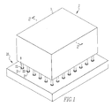
- FIG. 1 shown is an exemplary embodiment of the column grid array connector of the present invention.
- FIG. 5 through 8 shown is an exemplary method of disposing a column of solder about a tail portion of a terminal of an electrical connection.
- the present invention provides an apparatus adapted to form an improved connection between an electrical connector 2 and a substrate 20.
- This invention provides a solder column 8 that addresses the primary obstacles that are presented with large area array components, including CTE mismatch and coplanarity, by providing a more compliant connection between the electrical connector 2 and the substrate 20.
- the present invention provides an improved process for attaching columns of solder 7 to the contact terminals 5 of the electrical connector 2 to form solder columns 8.
- This invention is especially adapted for use with relatively large connectors having a high number of I/O terminals 5, and more particularly for connectors having large area array configurations that require increased I/O requirements along with increased density, such as electrical connectors over about 1000 positions and up to about 7000 positions. It relies on the concept of increasing the length or height of a solder column 8 so that there is greater compliance in the connection between the terminal 5 and the substrate 20.
- the increased compliance allows the terminal 5 and solder joint 24 to absorb higher stresses (usually resulting from the CTE mismatch of the print circuit board 20 and the connector housing 3) thereby avoiding fracture of the solder joint 24 between the terminal 5 and the printed circuit board 20.
- at least a portion of the tail portion 6 of the contact 5 extends into the column of solder 7 a predetermined distance thereby forming a solder column 8 which adds mechanical rigidity to the connection.
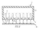
- Figures 1 through 4 depict an electrical connector 2 including a connector housing 3 having a plurality of contact terminals 5 disposed therein and a mounting surface 4 formed thereon.
- Each of the individual terminals 5 has a tail portion 6 formed at a distal end. Tails 6 pass through respective openings 11 formed in mounting surface 4 and extend out from housing 3.
- Terminals 6 are formed of an electrically conductive material.
- tails 6 are formed integral with terminals 5.
- terminal tails 6 are formed from a metal material having a melting point greater than the melting point of the column of solder 7.
- the contact terminals 5 and tails 6 extend outward from opposite sides of housing 3 and the tails 6 are adapted for connection to substrate 20 through solder column 8.
- an extended column of solder 7 is disposed about tail portion 6 of each of the plurality of terminal contacts 5 such that the tail 6 of each terminal 5 extends over at least a portion of the column of solder 7 to form a solder column 8.
- the tail 6 extends a predetermined distance into a center region or core 10 of the column of solder 7 thereby forming solder column 8.
- Tail portion 6, by extending into the solder column 8, adds mechanical rigidity to the connection and allows the length 13 of solder column 8 to be extended thereby improving the compliance between connector 2 and substrate 20. This increased compliance allows the connection to absorb higher stresses thereby avoiding rupture of the solder joint 24.
- the column of solder 7 is disposed about at least a portion of the tail portion 6.
- the longitudinal axis of tail 6 is oriented along the longitudinal axis of the solder column 8 and forms part of the longitudinal axis.
- the tail 6 thus forms a core 10 of the solder column 8.
- the solder column 8 has a tip 12 formed at its distal end that is adapted for connection to the substrate 20.
- the tail 6 extends a predetermined distance into the column of solder 7 to form a core 10 of the solder column 8.
- the distance that the tail 6 extends into the solder column 8 depends on the particular application, but preferably the tail 6 extends into the solder column 8 a sufficient distance, such as between approximately 5-20% of the length of the solder column 8, to provide mechanical strength and rigidity to the connection, while at the same time providing a compliant mechanical connection between the connector 2 and the substrate 20.
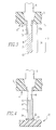
- the solder column 8 is formed having an overall length 13.
- the solder column 8 is preferably formed such that more overall length 13 of the solder column 8 is formed of solder only.
- the overall length 13 of each of the solder columns 8 includes a first length 13a having the terminal tail portion 6 surrounded by the solder 7 and a second length 13b comprising solder 7 material only (e.g., no tail portion 6 in the center region).
- the second length 13b makes up a greater percentage of the overall length 13 of the solder column 8.
- the first length 13a provides improved mechanical strength to the connection, while the second length 13b provides improved compliance to the connection.
- the preferred distance that the tail extends into the solder column 8 must be determined to provide the desired mechanical rigidity while at the same time also maintaining the desired compliancy of the connection.
- a purpose of the solder column 8 is to provide a compliant connection between the two pieces.
- the solder column 8 should preferably allow some motion/movement between the pieces and the solder column 8 acts to absorb this motion or offset between the pieces.
- DNP Distance to Neutral Point
- the terminal tail 6 forming the core 10 of the solder column 8 acts to reinforce the solder column 8 and this metal core 10 of the solder column 8 increases the mechanical properties of the attachment between the connector 2 and the substrate 20.
- the metal core 10 of the tail 6 also helps prevent collapse of the solder column 8 during the reflow process.
- solder column 8 has a diameter of about 0.020-0.0225 inch and a length of about 0.050 inch in a first embodiment and about 0.087 inch in a second embodiment.
- the inductance and electrical characteristics of the solder column 8 have been found to be more preferred with the 0.050 inch.
- the column of solder 7 may comprise any solder medium which has properties conductive to forming an electrical and a mechanical connection between the electrical connector 2 and the substrate 20.
- the column of solder 7 is an electrically conductive material.
- the solder column 8 is a relatively high melting point solder having a melting point greater than about 183°C.
- the column of solder 7 is a 90Pb 10Sn alloy. The 90Pb 10Sn alloy preferably keeps some mechanical properties between the temperatures of 183°C and 213°C and does not become completely liquidious until it reaches a temperature greater than about 213 C.
- the substrate 20 is provided with a plurality of electrically conductive contact pads 21 (or alternatively vias or traces) adapted for receiving a solder column 8.
- the contact pads 21 are adapted for completing an electrical path between the electrical connector 2 and the substrate 20 and also for forming a mechanical connection between a contact pad 21 and a solder column 8.
- the contact pads 21 are formed from a copper material.
- connection between the solder column 8 and the substrate 20 is accomplished using an attachment medium 22 which mechanically and electrically connects the electrical connector 2 to a substrate 20.
- a solder medium or a resin flux medium is used to form the attachment medium 22.
- an eutectic solder material having a relatively low melting point with respect to the melting point of the material of the solder column 8 is used.
- the terminal 5 has a melting temperature greater than the melting point of the solder column 8
- solder column 8 has a melting point greater than the relatively low melting point of the attachment solder 22 which completes the connection between the connector 2 and the substrate 20.
- the low melting point solder 22 actually forms the final connection 24 between the solder column 8 and the contact pad 21.
- An activation material such as a flux or a mild acid, may also be used to help clean the surface of the contact pad 21.
- connection of the solder column 8 to the substrate 20 is accomplished using conventional methods.
- the solder medium 22 is disposed between the tip 12 of the solder column 8 and the contact pad 21 of the substrate 20.
- the solder column 8 is positioned over the contact pad 21.
- the combination is then heated to a temperature at which the low temperature solder medium 22 achieves a liquidious form.
- the combination is then allowed to cool to form the connection 24 between the solder column 8 and the contact pad 21.
- a small percentage of the high melting point solder of the solder column 8 may, on a microscopic level, form part of the connection joint 24.
- solder 22 generally causes the solder 22 to ball up when it goes into a liquidious form. This causes the solder column 8 to self-center on the substrate 20 that it is attaching to.
- a non-removable connection is formed between the connector 2 and the substrate 20, meaning that the connector 2 cannot be removed from the substrate 20 without damaging the solder column 8, the contact pad 21, or the connection joint 24.
- Figures 5 through 8 show an exemplary process of attaching the column of solder 7 to the terminal tail portion 6 in accordance with the present invention.
- Figures 5 through 8 shows a fixture 30 to be used in the process of attaching a column of solder 7 to a tail 6 portion of a terminal 5 to form a solder column 8.
- Fixture 30 is formed having a plurality of bores, or holes, 31 that extend a predetermined depth therein. Each bore 31 has a top 32 and a bottom 33. The depth is predetermined based on the desired length 13 of the solder column 8 that is being formed.
- the fixture is designed such that the depth of one or more of the bores 31 is variable in order to control the final coplanarity of the connector 2 in relation to the surface of the substrate 20.
- the coplanarity may be established such that it matches the surface contour of the substrate 20 to which it will be attached.
- Coplanarity means that the plane defined by the tips 12 of the solder columns 8 is coplanar with the plane defined by the surface of the substrate 20 when the connector 2 is placed on the substrate 20.
- the bores 31 are preferably shaped to conform to the desired shape of the solder column 8. This would include the top 32 where the solder column 8 will attach to the tail 6 and also the bottom 33 which is preferably formed having a shape that is adapted for forming a connection to a particular substrate 20. As shown in Figure 5, the top 32 is preferably formed having a flared design to allow the solder to form a better connection with the tail 6.
- the bottom 33 is preferably formed having a spherical shape to form a solder column 8 having a spherical shaped tip 12. Alternatively, the bottom 33 may have a flat shape.
- Figure 5 also shows an optional channel 40 that may be present in an alternative embodiment to connect bores 31 to a point outside of the fixture 30.
- Channel 40 provides a path for venting of the liquidious solder material during formation of the solder column 8.
- the method of attaching the column of solder 7 to the tail 6 portion of an electrical connector terminal 5 to form solder column 8 includes providing a fixture 30 and cutting a plurality of columns of solder 7 to a predetermined length L and a predetermined diameter D depending on the particular application.
- the plurality of columns of solder 7 may be a solder preform, a non-eutectic solder, or a cut wire solder.
- a preferred application has columns of solder 7 that have a 0.020 inch diameter, and a length of either 0.050 inch or 0.087 inch. Disposing the cut columns of solder 7 into the bores 31 in fixture 30.
- the next step of the above method is heating the fixture 30 having the cut columns of solder disposed therein to a temperature above the melting point of the solder 7 to form a liquidious pool of solder 7a in each bore 31.
- the temperature is below the melting point of the material of the tail 6.
- the solder is a high melting point solder alloy, such as a 90PB 10Sn alloy. Even more preferably, the solder has a melting point greater than about 183°C.
- the method includes providing an electrical connector 2 having a plurality of contact terminal 5 disposed therein and tail 6 portions of each terminal 5 extending through the housing 3 of the connector 2 and extending therefrom.
- the tails 6 are preferably a metallic material having a melting point higher than the melting point of the solder 7.
- the step of providing the electrical connector includes disposing the plurality of tail 6 portion into the bores 31 and the liquidious pools of solder 7a, and cooling the fixture 30 and connector 2 combination so that the solder pools 7a solidify forming a solder column 8 having the tail extending at least some distance into the solder column 8.
- a first length 13a is formed having the tail portion 6 that forms a core 10 of the solder column 8.
- a second length 13b is formed having solder material 7 only. Removing the electrical connector 2 having a plurality of solder columns 8 depending therefrom from the fixture 30.
- the lengths of the solder columns 8 may be varied by setting the depth of one or more of the bores 31 (as described more fully below) to control a final coplanarity of the connector 2, or alternatively, the tips 12 of the solder columns 8 may be sheared or cut to length to set the coplanarity for a given application.
- Coplanarity is defined as the plane or co-plane formed by a plurality of tips 12 formed at the distal ends of each of the lengths of the solder columns 8 and the plane defined by the surface of the substrate 20 when the connector having solder columns 8 is disposed over the substrate 20.
- the coplanarity of the tips 12 is adapted for each application to correspond to the coplanarity of the surface of the substrate 20 to which the connector 2 will be affixed.
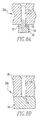
- Figure 8A and 8B show alternative configurations of fixture 30 and bottom 33.
- Figure 8A shows fixture 30a having a bore 31a that extends all the way through the fixture 30a.
- a pin structure 34 is provided having a body 35 that extends upward into bore 3 la and a head 36 attached to the body 35.
- the pin body 35 is sized to have a diameter slightly smaller than the diameter of bore 31a.
- the fit of pin body 35 into bore 3 la is such that minimal or no leakage of liquid from bore 31a above pin body 35 occurs.
- a seal 37 may also be provided to contain any leakage of liquid solder pass pin body 35. Seal 37 is preferably formed having a circular donut like shape with an inner diameter slightly smaller than the pin body 35 diameter and an outer diameter greater than the diameter of bore 31a.
- the pin structure 34 provides a control feature for varying the depth of each bore 31a by sliding the pin structure 34 into or out of bore 31a, thereby allowing for control of the final length of solder column 8 and the coplanarity of the connector.
- the pin structure 34 also provides an ejection feature that facilitates removal of the completed solder column 8 and for cleaning the fixture 30.
- Figure 8B shows a two piece laminated fixture 30b for producing flat bottom 33b solder columns 8.
- the two piece fixture 30b preferably is a laminated structure including a first piece 38 having a plurality of bores 31b formed therein that pass through the first piece 38 and a second piece 39 that is disposed under the first piece 38 to cover and close bore 31b.
- This laminated flat bottom design is less expensive than the fixture 30 having a spherical bottom 33 and also the fixture 30a having a pin structure 34. This provides benefits in tooling, fixture manufacturing, and design.
- This laminated design of fixture 30b also provides for adjustment of the length of the solder column 8, facilitates ejection of the solder column 8 from the fixture 30b, and assists in the cleaning of the bores 31b of fixture 30b.
Landscapes
- Engineering & Computer Science (AREA)
- Manufacturing & Machinery (AREA)
- Microelectronics & Electronic Packaging (AREA)
- Coupling Device And Connection With Printed Circuit (AREA)
- Multi-Conductor Connections (AREA)
- Manufacturing Of Electrical Connectors (AREA)
- Connections Effected By Soldering, Adhesion, Or Permanent Deformation (AREA)
- Electric Connection Of Electric Components To Printed Circuits (AREA)
Applications Claiming Priority (2)
| Application Number | Priority Date | Filing Date | Title |
|---|---|---|---|
| US460008 | 1999-12-13 | ||
| US09/460,008 US6353191B1 (en) | 1999-12-13 | 1999-12-13 | Column grid array connector |
Publications (2)
| Publication Number | Publication Date |
|---|---|
| EP1111973A2 true EP1111973A2 (de) | 2001-06-27 |
| EP1111973A3 EP1111973A3 (de) | 2003-07-16 |
Family
ID=23827047
Family Applications (1)
| Application Number | Title | Priority Date | Filing Date |
|---|---|---|---|
| EP00126576A Withdrawn EP1111973A3 (de) | 1999-12-13 | 2000-12-12 | Kolumn-Matrixverbinder und Methode für das Verbinden eines Lötkolumn |
Country Status (4)
| Country | Link |
|---|---|
| US (1) | US6353191B1 (de) |
| EP (1) | EP1111973A3 (de) |
| JP (1) | JP2001217027A (de) |
| TW (1) | TW490085U (de) |
Cited By (2)
| Publication number | Priority date | Publication date | Assignee | Title |
|---|---|---|---|---|
| FR2845520A1 (fr) * | 2002-10-04 | 2004-04-09 | Wavecom | Procede et dispositif de remise en forme, notamment de remise en etat de la planeite, des elements d'interconnexion d'un module electronique, par ajout de matiere |
| CN120690693A (zh) * | 2025-06-05 | 2025-09-23 | 西安晶捷电子技术有限公司 | 一种用于ccga封装器件植柱的工装及方法 |
Families Citing this family (6)
| Publication number | Priority date | Publication date | Assignee | Title |
|---|---|---|---|---|
| DE10032337A1 (de) * | 2000-07-04 | 2002-01-17 | Bosch Gmbh Robert | Anschlußträger und Verfahren zum Verbinden des Anschlußträgers mit einem Spritzgußteil |
| US7530820B2 (en) * | 2007-05-29 | 2009-05-12 | Myoungsoo Jeon | Temperature-activated self-extending surface mount attachment structures |
| JP2012018892A (ja) * | 2010-07-09 | 2012-01-26 | Tyco Electronics Japan Kk | 電気部品 |
| US9537234B2 (en) * | 2013-08-08 | 2017-01-03 | Globalfoundries Inc. | Method of making a solder tail extender connector |
| JP6230520B2 (ja) * | 2014-10-29 | 2017-11-15 | キヤノン株式会社 | プリント回路板及び電子機器 |
| DE102021109720A1 (de) | 2021-04-19 | 2022-10-20 | Turck Holding Gmbh | Leiterplatte, elektrisches Steckermodul und Herstellverfahren |
Family Cites Families (12)
| Publication number | Priority date | Publication date | Assignee | Title |
|---|---|---|---|---|
| US3601662A (en) * | 1969-08-11 | 1971-08-24 | Marconi Co Canada | Terminations for cordwood modules |
| US4419814A (en) | 1981-10-15 | 1983-12-13 | General Signal Corporation | Method of making a bobbin construction for autotransformer ballast |
| US5244143A (en) | 1992-04-16 | 1993-09-14 | International Business Machines Corporation | Apparatus and method for injection molding solder and applications thereof |
| US5324892A (en) * | 1992-08-07 | 1994-06-28 | International Business Machines Corporation | Method of fabricating an electronic interconnection |
| US5334804A (en) * | 1992-11-17 | 1994-08-02 | Fujitsu Limited | Wire interconnect structures for connecting an integrated circuit to a substrate |
| US5573172A (en) | 1993-11-08 | 1996-11-12 | Sawtek, Inc. | Surface mount stress relief hidden lead package device and method |
| JPH07320800A (ja) * | 1994-05-18 | 1995-12-08 | Star Micronics Co Ltd | 端子及びその製造方法 |
| US5542174A (en) | 1994-09-15 | 1996-08-06 | Intel Corporation | Method and apparatus for forming solder balls and solder columns |
| US5639696A (en) | 1996-01-31 | 1997-06-17 | Lsi Logic Corporation | Microelectronic integrated circuit mounted on circuit board with solder column grid array interconnection, and method of fabricating the solder column grid array |
| US6042389A (en) * | 1996-10-10 | 2000-03-28 | Berg Technology, Inc. | Low profile connector |
| US5791911A (en) | 1996-10-25 | 1998-08-11 | International Business Machines Corporation | Coaxial interconnect devices and methods of making the same |
| US5911583A (en) | 1997-11-24 | 1999-06-15 | Raytheon Company | Stacked electrical circuit having an improved interconnect and alignment system |
-
1999
- 1999-12-13 US US09/460,008 patent/US6353191B1/en not_active Expired - Fee Related
-
2000
- 2000-12-11 TW TW089221451U patent/TW490085U/zh unknown
- 2000-12-12 EP EP00126576A patent/EP1111973A3/de not_active Withdrawn
- 2000-12-13 JP JP2000378698A patent/JP2001217027A/ja active Pending
Cited By (2)
| Publication number | Priority date | Publication date | Assignee | Title |
|---|---|---|---|---|
| FR2845520A1 (fr) * | 2002-10-04 | 2004-04-09 | Wavecom | Procede et dispositif de remise en forme, notamment de remise en etat de la planeite, des elements d'interconnexion d'un module electronique, par ajout de matiere |
| CN120690693A (zh) * | 2025-06-05 | 2025-09-23 | 西安晶捷电子技术有限公司 | 一种用于ccga封装器件植柱的工装及方法 |
Also Published As
| Publication number | Publication date |
|---|---|
| US6353191B1 (en) | 2002-03-05 |
| JP2001217027A (ja) | 2001-08-10 |
| EP1111973A3 (de) | 2003-07-16 |
| TW490085U (en) | 2002-06-01 |
Similar Documents
| Publication | Publication Date | Title |
|---|---|---|
| JP4018213B2 (ja) | 電気コネクタおよびその製造方法 | |
| US6127204A (en) | Column grid array or ball grid array pad on via | |
| EP1284523B1 (de) | Lötkugelkontakt und Leiterplatte mit solchem Kontakt | |
| JP2005512335A (ja) | ボールグリッドアレイパッケージ | |
| US20080070453A1 (en) | Solder-bearing contacts and method of manufacture thereof and use in connectors | |
| US6272741B1 (en) | Hybrid solder ball and pin grid array circuit board interconnect system and method | |
| US6353191B1 (en) | Column grid array connector | |
| US7204730B2 (en) | Circuit board inter-connection system and method | |
| GB2325354A (en) | Electrical connector or connection with concave ball-receiving site | |
| EP1313173B1 (de) | Pin-grid-array elektrischer Steckverbinder | |
| US6830462B1 (en) | Electrical connector housing | |
| JPH1065056A (ja) | バンプ・グリッド・アレイの作製方法および作製装置 | |
| US20020061687A1 (en) | Solder bearing grid array | |
| US20030114028A1 (en) | Solder-bearing lead | |
| US6012225A (en) | Method of making surface mount pads | |
| JP3274648B2 (ja) | 高融点ボールコネクタ及び高融点ボールコネクタ用コンタクト | |
| JP3122932B2 (ja) | 半田ボール付きコネクタ | |
| US6989591B1 (en) | Method for making an integrated circuit of the surface-mount type and resulting circuit | |
| JPH07106491A (ja) | ピングリッドアレイ部品とその実装方法 | |
| US20060249303A1 (en) | Connectorless electronic interface between rigid and compliant members using hemi-ellipsoidal surface features | |
| US20110101075A1 (en) | Apparatus and methods of attaching hybrid vlsi chips to printed wiring boards | |
| EP1536522B1 (de) | Verbinder hoher Packungsdichte mit Kontaktoberflächen vom Kugeltyp | |
| WO2010105086A1 (en) | Contact with tubular solder member | |
| CN101323056A (zh) | 锡球及使用该锡球的电连接器 | |
| JP2004319249A (ja) | 表面実装式電子部品の製造方法 |
Legal Events
| Date | Code | Title | Description |
|---|---|---|---|
| PUAI | Public reference made under article 153(3) epc to a published international application that has entered the european phase |
Free format text: ORIGINAL CODE: 0009012 |
|
| AK | Designated contracting states |
Kind code of ref document: A2 Designated state(s): AT BE CH CY DE DK ES FI FR GB GR IE IT LI LU MC NL PT SE TR |
|
| AX | Request for extension of the european patent |
Free format text: AL;LT;LV;MK;RO;SI |
|
| PUAL | Search report despatched |
Free format text: ORIGINAL CODE: 0009013 |
|
| AK | Designated contracting states |
Designated state(s): AT BE CH CY DE DK ES FI FR GB GR IE IT LI LU MC NL PT SE TR |
|
| AX | Request for extension of the european patent |
Extension state: AL LT LV MK RO SI |
|
| AKX | Designation fees paid | ||
| REG | Reference to a national code |
Ref country code: DE Ref legal event code: 8566 |
|
| STAA | Information on the status of an ep patent application or granted ep patent |
Free format text: STATUS: THE APPLICATION IS DEEMED TO BE WITHDRAWN |
|
| 18D | Application deemed to be withdrawn |
Effective date: 20040117 |