EP1111833A2 - Transmission quality monitoring system with less delay - Google Patents
Transmission quality monitoring system with less delay Download PDFInfo
- Publication number
- EP1111833A2 EP1111833A2 EP00311354A EP00311354A EP1111833A2 EP 1111833 A2 EP1111833 A2 EP 1111833A2 EP 00311354 A EP00311354 A EP 00311354A EP 00311354 A EP00311354 A EP 00311354A EP 1111833 A2 EP1111833 A2 EP 1111833A2
- Authority
- EP
- European Patent Office
- Prior art keywords
- signal
- transmission
- field
- code
- fec
- Prior art date
- Legal status (The legal status is an assumption and is not a legal conclusion. Google has not performed a legal analysis and makes no representation as to the accuracy of the status listed.)
- Withdrawn
Links
- 230000005540 biological transmission Effects 0.000 title claims abstract description 219
- 238000012544 monitoring process Methods 0.000 title claims description 21
- 230000003287 optical effect Effects 0.000 claims abstract description 99
- 238000012937 correction Methods 0.000 claims abstract description 22
- 230000008054 signal transmission Effects 0.000 claims abstract description 14
- 238000004364 calculation method Methods 0.000 claims description 93
- 238000000034 method Methods 0.000 claims description 24
- 238000004891 communication Methods 0.000 description 14
- 239000013307 optical fiber Substances 0.000 description 14
- 238000010586 diagram Methods 0.000 description 9
- 239000000872 buffer Substances 0.000 description 7
- 238000001514 detection method Methods 0.000 description 5
- 238000011156 evaluation Methods 0.000 description 3
- 238000006243 chemical reaction Methods 0.000 description 2
- 238000003326 Quality management system Methods 0.000 description 1
- 238000013500 data storage Methods 0.000 description 1
- 238000007726 management method Methods 0.000 description 1
- 238000012986 modification Methods 0.000 description 1
- 230000004048 modification Effects 0.000 description 1
- 238000012545 processing Methods 0.000 description 1
- 230000001360 synchronised effect Effects 0.000 description 1
- 238000012546 transfer Methods 0.000 description 1
Images





Classifications
-
- H—ELECTRICITY
- H04—ELECTRIC COMMUNICATION TECHNIQUE
- H04L—TRANSMISSION OF DIGITAL INFORMATION, e.g. TELEGRAPHIC COMMUNICATION
- H04L1/00—Arrangements for detecting or preventing errors in the information received
- H04L1/20—Arrangements for detecting or preventing errors in the information received using signal quality detector
Definitions
- the present invention relates to a system and a method for monitoring transmission quality of data transmitted on a transmission communication network. More particularly, the present invention relates to a system and a method for monitoring transmission quality of data transmitted via relaying stations.
- Fig. 1 shows an example of the transmission communication network using such a transmission quality monitoring system.
- a first optical relaying unit 103 1 and a second optical relaying unit 103 2 are arranged between an optical transmission end station 101 and an optical reception end station 102.
- An optical signal is sent out from the optical transmission end station 101, and then reaches the first optical relaying unit 103 1 by a first optical fiber transmission path 104 1 , and then the optical signal is sent out from the first optical relaying unit 103 1 to the second optical relaying unit 1032 on a second optical fiber transmission path 104 2 .
- the optical signal is transmitted to the optical reception end station 102 last on a third optical fiber transmission path 104 3 .
- the monitor of the transmission quality in detail, it is necessary to monitor not only the transmission quality in the end-to-end interval 105 between the optical transmission end station 101 and the optical reception end station 102 but also the transmission quality in each of the optical relay intervals 106 1 to 106 3 . Therefore, the monitor of the transmission quality on the transmission path must be carried out in both of these optical relay intervals 106 1 to 106 3 , and the end-to-end interval 105.
- Fig. 2 shows the structure of a conventionally proposed optical relaying unit used in such a transmission quality monitoring system.
- the optical relaying unit 103 is composed of a photoelectric converter 111, which is connected to the optical fiber transmission path 104 to receive the optical signal sent through the path 104.
- the photoelectric converter 111 converts the received optical signal into an electrical signal.
- the electrical signal after the conversion is sent to a frame synchronization section 112.
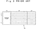
- Fig. 3 shows the form of the transmission signal in the conventional transmission communication network.
- the signal 120 sent out of the optical transmission end station 101 is composed of n frames from the first frame F1 to the n-th frame Fn. Each of the frames is composed of an overhead field 121, a data field 122 and an additional bits field 123 for forward error correction (FEC). Coded data for the quality monitor is stored in the overhead fields 121.
- FEC forward error correction
- a frame synchronizing section 112 establishes the synchronization with each frame.
- the signal in which synchronization has been established is sent to a descrambling section 113.
- the descrambling section 113 releases the scrambled state of the synchronized signal to supply the descrambled signal to a FEC decoding section 114.
- the FEC decoding section 114 carries out a FEC decoding operation to the descrambled signal.
- the next transmission quality detecting section 115 detects transmission quality using the FEC code to send out to a quality data transferring section 116.
- the quality data transferring section 116 operates to incorporate and output the detected transmission quality data into the overhead fields 121 appropriately.
- This signal which has been outputted from the quality data transfer section 116 is coded by the FEC coding section 117 and is scrambled by the scramble section 118. Then, the electrical signal is converted into an optical signal by the photoelectric converter 119 and is sent out on the optical fiber transmission path 104 of the next stage.
- the transmission quality data is detected by the optical relaying units 103 1 and 103 2 shown in Fig. 1 as in the optical reception end station 102.
- the detected transmission quality data is incorporated in the overhead fields of the next signal and is sent out to the downstream side.
- each of optical relaying units 103 1 and 103 2 must carry out a decoding operation by the FEC decoding section 114 and a coding operation by the FEC coding section 117. Therefore, the circuit scale of each of the optical relaying units 103 1 and 103 2 increases but also the transmission delay is caused due to these signal processes.
- JP-A-Heisei 3-289746 Japanese Laid Open Patent Application
- data of connection quality, transmission quality and stability quality of a communication network are collected and stored in a data storage section.
- a signal processing section evaluates integrated performance of the communication network based on the data and a performance evaluation measure in which connection quality, transmission quality and stability quality of the communication network are integrated.
- a display unit displays the integrated performance of the communication network in the form of figures which represent communication nodes and transmission paths of the communication network.
- JP-A-Heisei 9-64941 a transmission quality management system is disclosed in Japanese Laid Open Patent Application (JP-A-Heisei 9-64941).
- a regular buffer and a spare buffer are provided to store calculation data of calculation items.
- the calculation data of the determined item is stored in the regular buffer directly.
- the calculation data of previously set items is stored in the spare buffer corresponding to the calculation item.
- the calculation data of the determined item is read out from the spare buffer and added to the regular buffer. Then, all the spare buffers are cleared to "0".
- an object of the present invention is to provide a transmission quality monitoring system and a method of monitoring the transmission quality, in which the hardware structure of a relaying unit or a relaying station can be simplified when forward direction error correction (FEC) control is used.
- FEC forward direction error correction
- Another object of the present invention is to provide a transmission quality monitoring system and a method of monitoring the transmission quality, in which it is possible to prevent transmission delay of a signal to a reception end station as less as possible.
- an optical signal transmission system includes a transmission station, at least one relaying unit connected to the transmission station via an optical path, and a reception station connected to the relaying unit via an optical path.
- the transmission station transmits a transmission signal to the reception station via the relaying unit, the transmission signal includes a first monitor code which is not subjected to a FEC (forward error correction) coding operation.
- the relaying unit detects a transmission error in the transmission signal without a FEC decoding operation based on the first monitor code.
- the transmission signal may include a plurality of frames, and each of the plurality of frames may include an overhead field, a data field and a FEC code field.
- the first monitor code may be stored in ones of the overhead fields for the plurality of frames as a first field group.
- the transmission signal may include and a second monitor code which is subjected to the FEC (forward error correction) coding operation in addition to the first monitor code.
- the reception station carries out the FEC decoding operation to the transmission signal and detects a transmission error in the transmission signal based on the second monitor code.
- the reception station may detect a transmission error in the transmission signal between the relaying unit and the reception station based on the first monitor code.
- the transmission signal may include a plurality of frames, and each of the plurality of frames may include an overhead field, a data field and a FEC code field.
- the first monitor code and the second monitor code may be stored in first and second field groups of the overhead fields for the plurality of frames, respectively.
- the transmission signal may include a plurality of frames, and each of the plurality of frames may include an overhead field, a data field and a FEC code field.
- the first monitor code and the second monitor code may stored in first and second field groups of the overhead fields for the plurality of frames, respectively.
- the transmission station may include a transmission signal coding circuit which includes a first BIP (Bit Interleaved Parity) calculating section, a FEC coding section, a second BIP calculating section and a scrambling section.
- the first BIP (Bit Interleaved Parity) calculating section carries out a first BIP calculation to a signal to be transmitted to store a result of the first BIP calculation as the second monitor code in the second field group.
- the FEC coding section carries out a FEC coding operation to the first BIP calculation result and data of the signal after the first BIP calculation, to store an FEC code obtained as a result of the FEC coding operation in the FEC code field.
- the second BIP calculating section carries out a second BIP calculation to the signal after the FEC coding operation to store a BIP code as the first monitor code in the first field group.
- the scrambling section scrambles the signal after the second BIP calculation based on a predetermined generation polynomial, an optical signal corresponding to the scrambled signal being transmitted to the reception station as the transmission signal.
- the transmission signal may include a plurality of frames, and each of the plurality of frames includes an overhead field, a data field and a FEC code field.
- the first monitor code and the second monitor code are stored in first and second field groups of the overhead fields for the plurality of frames, respectively.
- the relaying unit receives the transmission signal, and includes a descrambling section, a first BIP check section, a BIP calculating section and a scrambling section.
- the descrambling section descrambles the received signal based on a predetermined generation polynomial.
- the first BIP check section carries out a third BIP calculation to the descrambled signal and compare a result of the third BIP calculation and the first monitor code stored in the first field group to determine whether the received signal has any transmission error.
- the BIP calculating section carries out a fourth BIP calculation to the descrambled signal to store a result of the fourth BIP calculation as the first monitor code in the first field group.
- the scrambling section scrambles the received signal after the fourth BIP calculation, an optical signal corresponding to the received signal after the scrambling being transmitted to the reception station as the transmission signal.
- the transmission signal may include a plurality of frames, and each of the plurality of frames includes an overhead field, a data field and a FEC code field.
- the first monitor code and the second monitor code are stored in first and second field groups of the overhead fields for the plurality of frames, respectively.
- the reception station receives the transmission signal, and includes a descrambling section, an FEC decoding section and a BIP check section.
- the descrambling section descrambles the received signal based on a predetermined generation polynomial.
- the FEC decoding section carries out the FEC decoding operation and an error correction to the descrambled signal to produce an object signal.
- the BIP check section carries out a fifth BIP calculation to the object signal and compares a result of the fifth BIP calculation to the second monitor code stored in the second field group to detect any transmission error.
- the reception may further include a second BIP check section, which carries out a sixth BIP calculation to the descrambled signal and compares a result of the sixth BIP calculation and the first monitor code stored in the first field group to detect any transmission error.
- a method of monitoring a transmission quality in an optical signal transmission system including a transmission station, at least one relaying unit connected to the transmission station via an optical path, and a reception station connected to the relaying unit via an optical path, is attained by transmitting a transmission signal from the transmission station to the reception station via the relaying unit, the transmission signal includes a first monitor code which is not subjected to a FEC (forward error correction) coding operation, and by detecting in the relaying unit, a transmission error in the transmission signal without a FEC decoding operation based on the first monitor code.
- FEC forward error correction
- the transmission signal may include a plurality of frames, each of the plurality of frames may include an overhead field, a data field and a FEC code field.
- the first monitor code may be stored in ones of the overhead fields for the plurality of frames as a first field group.
- the method may further include carrying out in the reception station, the FEC decoding operation to the transmission signal and detects a transmission error in the transmission signal based on the second monitor code. Also, the method may be further attained by detecting in the reception station, a transmission error in the transmission signal between the relaying unit and the reception station based on the first monitor code.
- the transmission signal may include a plurality of frames, each of the plurality of frames may include an overhead field, a data field and a FEC code field, and the first monitor code and the second monitor code may be stored in first and second field groups of the overhead fields for the plurality of frames, respectively.
- the transmitting may be attained by carrying out a first BIP calculation to a signal to be transmitted to store a result of the first BIP calculation as the second monitor code in the second field group, by carrying out a FEC coding operation to the first BIP calculation result and data of the signal after the first BIP calculation, to store an FEC code obtained as a result of the FEC coding operation in the FEC code field, by carrying out a second BIP calculation to the signal after the FEC coding operation to store a BIP code as the first monitor code in the first field group, and by scrambling the signal after the second BIP calculation based on a predetermined generation polynomial, an optical signal corresponding to the scrambled signal being transmitted to the reception station as the transmission signal.
- the detecting in the relaying unit may be attained by receiving the transmission signal, by descrambling the received signal based on a predetermined generation polynomial, by carrying out a third BIP calculation to the descrambled signal and compare a result of the third BIP calculation and the first monitor code stored in the first field group to determine whether the received signal has any transmission error, by carrying out a fourth BIP calculation to the descrambled signal to store a result of the fourth BIP calculation as the first monitor code in the first field group, and by scrambling the received signal after the fourth BIP calculation, an optical signal corresponding to the received signal after the scrambling being transmitted to the reception station as the transmission signal.
- the method may be attained by receiving the transmission signal by the reception station, by descrambling the received signal based on a predetermined generation polynomial, by carrying out the FEC decoding operation and an error correction to the descrambled signal to produce an object signal, and by carrying out a fifth BIP calculation to the object signal and compares a result of the fifth BIP calculation to the second monitor code stored in the second field group to detect any transmission error.
- the method may be further attained by carrying out a sixth BIP calculation to the descrambled signal and compares a result of the sixth BIP calculation and the first monitor code stored in the first field group to detect any transmission error.
- an optical signal relaying unit includes a descrambling section, a first BIP check section and a BIP calculating section.
- the descrambling section descrambles a reception signal transmitted from an upper stream based on a predetermined generation polynomial.
- the first BIP check section carries out a first BIP calculation to the descrambled signal and compare a result of the first BIP calculation and a first monitor code stored in a first predetermined overhead field group of the reception signal to determine whether the reception signal has any transmission error.
- the BIP calculating section carries out a second BIP calculation to the descrambled signal to store a result of the second BIP calculation as the first monitor code in the first overhead field group.
- the scrambling section scrambles the scrambled signal after the second BIP calculation, an optical signal corresponding to the scrambled signal being transmitted to the reception station as the transmission signal.
- a reception station includes a descrambling section, an FEC decoding section, a BIP check section and a BIP check section.
- the descrambling section descrambles a reception signal transmitted from an upper stream based on a predetermined generation polynomial.
- the FEC decoding section carries out an FEC decoding operation and an error correction to the descrambled signal to produce an object signal.
- the BIP check section carries out a first BIP calculation to the object signal and compares a result of the first BIP calculation to a second monitor code stored in the second overhead field group of the reception signal to detect any transmission error.
- the BIP check section carries out a second BIP calculation to the descrambled signal and compares a result of the second BIP calculation and the first monitor code stored in the first overhead field group of the reception signal to detect any transmission error.
- FIG. 4 shows the overall structure of a transmission quality monitoring system according to an embodiment of the present invention.
- a first optical relaying unit 203 1 and a second optical relaying unit 203 2 are arranged between an optical transmission end station 201 and an optical reception end station 202.
- An optical signal is sent out from the optical transmission end station 201 and reaches the first optical relaying unit 203 1 via a first optical fiber transmission path 204 1 .
- the optical signal is sent out from the first optical relaying unit 203 1 to the second optical relaying unit 203 2 via a second optical fiber transmission path 204 2 .
- the optical signal is last transmitted to the optical reception end station 202 on a third optical fiber transmission path 204 3 .
- the transmission quality of a transmission signal is monitored in both of the end-to-end interval 205 and each of the optical relay intervals 206 1 to 206 3 .
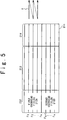
- Fig. 5 shows the frame structure of a transmission signal sent out from the optical transmission end station in this embodiment.
- the signal 211 which has been sent out from the optical transmission end station 201 is composed of n frames from the first frame F1 to n-th frame Fn.
- Each of the frames is composed of an overhead field 212, and a data field 213 and an FEC adding bit field 214.
- the first frame to k-th frame (1 ⁇ k ⁇ n) constitute the first overhead field group 212A.
- the (k+1)-th frame Fk+1 to the N-th frame Fn constitute the second overhead field group 212B.
- These frames F are scanned one frame by one frame, like the raster scan of a television.
- the first quality monitor code out of the object of the FEC coding operation and the FEC decoding operation is stored in the first overhead field group 212A.
- the second quality monitor code as the object of the FEC coding operation and the FEC decoding operation is stored in the second overhead field group 212B.
- the first quality monitor code stored in the first overhead field group 212A is used as monitor data to check FEC coded data itself for detection of a transmission error in a transmission path without the FEC decoding operation.
- the first quality monitor code is composed of a quality monitor code such as parity.
- the second quality monitor code stored in the second overhead field group 212B is composed of a quality monitor code such as parity, like the first quality monitor code.
- the second quality monitor code is used to check data after the FEC decoding operation and error correction for the detection of an end-to-end transmission error in the optical reception end station 202.
- the quality monitor code stored in the overhead field 121 and shown in Fig. 3 presupposes that the relaying unit 103 (Fig. 2) is composed of the FEC decoding section 114. Therefore, it is different from the first quality monitor code in this embodiment. Rather, the quality monitor code is similar to the second quality monitor code in this embodiment.
- Fig. 6 shows the structure of the transmission signal coding circuit 221 of the optical transmission end station 201 shown in Fig. 1.
- the transmission signal coding circuit 221 is composed of a first BIP (Bit Interleaved Parity) calculating section 222, which carries out a parity check for every block of predetermined units.
- the first BIP calculating section 222 carries out BIP calculation to input data 223 before a FEC coding operation. Then, the calculation result is inserted as the second quality monitor code in the second overhead field group 212B of the signal 211 shown in Fig. 5.
- the FEC coding section 225 arranged in the next stage carries out the FEC coding operation to the second quality monitor code stored in the second overhead field group 212B and data stored in the data filed 213 to produce an FEC code and stores the FEC code in the FEC overhead bit field 214.
- the second BIP calculating section 227 carries out BIP calculation to the signal after the FEC coding operation to produce a BIP code and inserts the BIP code in the first overhead field group 212A.
- the scramble section 229 codes the signal after BIP calculation in accordance with a previously set generation polynomial.
- the coded electrical signal is converted into an optical signal by a photoelectric converter 231, and is sent out in order in units of frames onto the first optical fiber transmission path 204 1 .
- Fig. 7 shows the structure of the optical relaying unit.
- the first optical relaying unit 203 1 is composed of a photoelectric converter 241 for receiving the optical signal sent on the first optical fiber transmission path 204 1 to convert the optical signal to an electric signal.
- a frame synchronization section 243 establishes the frame synchronization of the converted electric signal.
- a descrambling section 245 descrambles the electric signal in accordance with the previously set generation polynomial.
- a BIP check section 247 carries out the BIP calculation to the descrambled signal and compares the result of the BIP calculation and the first quality monitor code inserted in the first overhead field group 212A, to detects any transmission error of the optical relay interval based on the comparing result.
- a BIP calculating section 249 carries out a BIP calculation to the electric signal after the descrambling operation, and inserts a BIP code as the result of the BIP calculation in the first overhead field group 212A as the first quality monitor code.
- the scrambling section 251 scrambles the electric signal after the descrambling operation.
- the scrambled electrical signal is converted into an optical signal by a photoelectric converter 253 and is sent onto the second optical fiber transmission path 204 2 .
- the transmission error detected by the first optical relaying unit 203 1 shown in this Fig. 7 is transmitted to a host monitoring apparatus (not shown) through an exclusive use transmission path (not shown). Because the route and technique to the host monitoring apparatus are not directly related with the present invention, the detailed description is omitted.
- Fig. 8 shows an optical reception signal decoding circuit 271 of the optical reception end station 202 shown in Fig. 4 more specifically.
- the reception signal decoding circuit 271 is composed of a photoelectric converter 273 connected to one end of the third optical fiber transmission path 204 3 whose other end is connected to the second optical relaying unit 203 2 shown in Fig. 4.
- the photoelectric converter 273 converts the optical signal sent on the third optical fiber transmission path 204 3 into an electrical signal.
- a frame synchronization section 275 establishes the frame synchronization of the electric signal after the conversion.
- the descrambling section 277 descrambles the electric signal in accordance with the previously set generation polynomial.
- a BIP check section 279 carries out a BIP calculation to the descrambled signal in the next stage. Then, the BIP check section 279 compares the result of the BIP calculation and the first quality monitor code inserted in the first overhead field group 212A to detect a transmission error of the last optical relay interval 206 3 .
- the FEC decoding section 281 carries out the FEC decoding operation and an error correction to the descrambled signal.
- the BIP check section 283 carries out a BIP calculation to the signal after the FEC decoding operation. Then, the BIP check section 283 the error correction and compares a result of the BIP calculation and the BIP code as the second quality monitor code stored in the second overhead field group 212B of Fig. 5, to detect a transmission error of the output data 285 in the end-to-end interval 205 shown in Fig. 4.
- the first quality monitor code is arranged in the first half portion of the overhead fields 212 shown in Fig. 2, and the second quality monitor code is arranged in the second half of the overhead field group 212.
- the arrangement is not limit to this.
- the second quality monitor code may be arranged in the second half of the overhead field group 212 and the first quality monitor code may be arranged in the first half portion of the overhead field group 212.
- these quality monitor codes are divided and arranged into a plurality of areas, for example.
- the relaying station can detect the transmission error of the transmission data without carrying out the FEC decoding operation and the error correction to the transmission data by the FEC decoding section, using the first quality monitor code of the transmission data. In this way, it is not necessary to prepare the FEC decoding section in the relaying station so that the relaying station can be simplified in the hardware structure. Also, it is possible to prevent the transmission delay of the transmission data signal to the reception end station as less as possible. Thus, the reliability of the relaying station can be improved.
- the reception end station is provided with the transmission interval error detection section like the relaying station, the detection of the transmission interval error can be made possible in the same principle as the relaying station. It is possible to carry out perfect transmission quality management every interval.
- the relaying station carries out the BIP calculation to the received transmission data to perform a parity check for every block.
- the BIP code obtained thus is arranged as the first quality monitor code in the first region of the overhead fields. Therefore, the detection of the transmission interval error can be made possible in each interval.
- first quality monitor code and the second quality monitor code are distributed in the first half portion and the second half portion of a plurality of frames. Therefore, the data arrangement easy to find is realized.
- An optical signal transmission system includes a transmission station, at least one relaying unit connected to the transmission station via an optical path, and a reception station connected to the relaying unit via an optical path.
- the transmission station transmits a transmission signal to the reception station via the relaying unit, the transmission signal includes a first monitor code which is not subjected to a FEC (forward error correction) coding operation.
- the relaying unit detects a transmission error in the transmission signal without a FEC decoding operation based on the first monitor code.
Landscapes
- Engineering & Computer Science (AREA)
- Quality & Reliability (AREA)
- Computer Networks & Wireless Communication (AREA)
- Signal Processing (AREA)
- Optical Communication System (AREA)
- Detection And Prevention Of Errors In Transmission (AREA)
- Monitoring And Testing Of Transmission In General (AREA)
Abstract
Description
A display unit displays the integrated performance of the communication network in the form of figures which represent communication nodes and transmission paths of the communication network.
The first monitor code and the second monitor code may be stored in first and second field groups of the overhead fields for the plurality of frames, respectively.
In this case, the method may be further attained by carrying out a sixth BIP calculation to the descrambled signal and compares a result of the sixth BIP calculation and the first monitor code stored in the first field group to detect any transmission error.
Claims (18)
- An optical signal transmission system comprising:a transmission station (201);at least one relaying unit (203) connected to said transmission station via an optical path (204); anda reception station (202) connected to said relaying unit via an optical path,wherein said transmission station transmits a transmission signal to said reception station via said relaying unit, said transmission signal includes a first monitor code which is not subjected to a FEC (forward error correction) coding operation, andsaid relaying unit detects a transmission error in said transmission signal without a FEC decoding operation based on said first monitor code.
- The optical signal transmission system according to claim 1, wherein said transmission signal comprises a plurality of frames,each of said plurality of frames includes an overhead field, a data field and a FEC code field, andsaid first monitor code is stored in ones of said overhead fields for said plurality of frames as a first field group.
- The optical signal transmission system according to claim 1 or 2, wherein said transmission signal includes a second monitor code which is subjected to said FEC (forward error correction) coding operation in addition to said first monitor code, and
said reception station carries out said FEC decoding operation to said transmission signal and detects a transmission error in said transmission signal based on said second monitor code. - The optical signal transmission system according to claim 3, wherein said reception station detects a transmission error in said transmission signal between said relaying unit and said reception station based on said first monitor code.
- The optical signal transmission system according to claim 3, wherein said transmission signal comprises a plurality of frames,each of said plurality of frames includes an overhead field, a data field and a FEC code field, andsaid first monitor code and said second monitor code are stored in first and second field groups of said overhead fields for said plurality of frames, respectively.
- The optical signal transmission system according to claim 1, wherein said transmission signal comprises a plurality of frames,each of said plurality of frames includes an overhead field, a data field and a FEC code field,said first monitor code and said second monitor code are stored in first and second field groups of said overhead fields for said plurality of frames, respectively, andsaid transmission station includes a transmission signal coding circuit which comprises:a first BIP (Bit Interleaved Parity) calculating section (222) which carries out a first BIP calculation to a signal to be transmitted to store a result of said first BIP calculation as said second monitor code in said second field group;a FEC coding section (225) which carries out a FEC coding operation to said first BIP calculation result and data of said signal after said first BIP calculation, to store an FEC code obtained as a result of said FEC coding operation in said FEC code field;a second BIP calculating section (227) which carries out a second BIP calculation to said signal after said FEC coding operation to store a BIP code as said first monitor code in said first field group; anda scrambling section (229) which scrambles said signal after said second BIP calculation based on a predetermined generation polynomial, an optical signal corresponding to said scrambled signal being transmitted to said reception station as said transmission signal.
- The optical signal transmission system according to claim 1 or 6, wherein said transmission signal comprises a plurality of frames,each of said plurality of frames includes an overhead field, a data field and a FEC code field,said first monitor code and said second monitor code are stored in first and second field groups of said overhead fields for said plurality of frames, respectively, andsaid relaying unit receives said transmission signal, and comprises:a descrambling section (245) which descrambles said received signal based on a predetermined generation polynomial;a first BIP check section (247) which carries out a third BIP calculation to said descrambled signal and compare a result of said third BIP calculation and said first monitor code stored in said first field group to determine whether said received signal has any transmission error;a BIP calculating section (249) which carries out a fourth BIP calculation to said descrambled signal to store a result of said fourth BIP calculation as said first monitor code in said first field group; anda scrambling section (251) which scrambles said received signal after said fourth BIP calculation, an optical signal corresponding to said received signal after said scrambling being transmitted to said reception station as said transmission signal.
- The optical signal transmission system according to any of claims 1, 6 and 7, wherein said transmission signal comprises a plurality of frames,each of said plurality of frames includes an overhead field, a data field and a FEC code field,said first monitor code and said second monitor code are stored in first and second field groups of said overhead fields for said plurality of frames, respectively, andsaid reception station receives said transmission signal, and comprises:a descrambling section (277) which descrambles said received signal based on a predetermined generation polynomial;an FEC decoding section (281) which carries out said FEC decoding operation and an error correction to said descrambled signal to produce an object signal; anda BIP check section (283) which carries out a fifth BIP calculation to said object signal and compares a result of said fifth BIP calculation to said second monitor code stored in said second field group to detect any transmission error.
- The optical signal transmission system according to claim 8, wherein said reception further comprises:
a second BIP check section (279) which carries out a sixth BIP calculation to said descrambled signal and compares a result of said sixth BIP calculation and said first monitor code stored in said first field group to detect any transmission error. - A method of monitoring a transmission quality in an optical signal transmission system including a transmission station, at least one relaying unit connected to said transmission station via an optical path, and a reception station connected to said relaying unit via an optical path, comprising:transmitting a transmission signal from said transmission station to said reception station via said relaying unit, said transmission signal includes a first monitor code which is not subjected to a FEC (forward error correction) coding operation; anddetecting in said relaying unit, a transmission error in said transmission signal without a FEC decoding operation based on said first monitor code.
- The method according to claim 10, wherein said transmission signal comprises a plurality of frames,each of said plurality of frames includes an overhead field, a data field and a FEC code field, andsaid first monitor code is stored in ones of said overhead fields for said plurality of frames as a first field group.
- The method according to claim 10 or 11, wherein said transmission signal includes a second monitor code which is subjected to said FEC (forward error correction) coding operation in addition to said first monitor code, andsaid method further comprises:carrying out in said reception station, said FEC decoding operation to said transmission signal and detects a transmission error in said transmission signal based on said second monitor code.
- The method according to claim 12, further comprising:
detecting in said reception station, a transmission error in said transmission signal between said relaying unit and said reception station based on said first monitor code. - The method according to claim 12, wherein said transmission signal comprises a plurality of frames,each of said plurality of frames includes an overhead field, a data field and a FEC code field, andsaid first monitor code and said second monitor code are stored in first and second field groups of said overhead fields for said plurality of frames, respectively.
- The method according to claim 10, wherein said transmission signal comprises a plurality of frames,each of said plurality of frames includes an overhead field, a data field and a FEC code field,said first monitor code and said second monitor code are stored in first and second field groups of said overhead fields for said plurality of frames, respectively, andsaid transmitting comprises:carrying out a first BIP calculation to a signal to be transmitted to store a result of said first BIP calculation as said second monitor code in said second field group;carrying out a FEC coding operation to said first BIP calculation result and data of said signal after said first BIP calculation, to store an FEC code obtained as a result of said FEC coding operation in said FEC code field;carrying out a second BIP calculation to said signal after said FEC coding operation to store a BIP code as said first monitor code in said first field group; andscrambling said signal after said second BIP calculation based on a predetermined generation polynomial, an optical signal corresponding to said scrambled signal being transmitted to said reception station as said transmission signal.
- The method according to claim 10 or 15, wherein said transmission signal comprises a plurality of frames,ach of said plurality of frames includes an overhead field, a data field and a FEC code field,said first monitor code and said second monitor code are stored in first and second field groups of said overhead fields for said plurality of frames, respectively, andsaid detecting in said relaying unit comprises:receiving said transmission signal;descrambling said received signal based on a predetermined generation polynomial;carrying out a third BIP calculation to said descrambled signal and compare a result of said third BIP calculation and said first monitor code stored in said first field group to determine whether said received signal has any transmission error;carrying out a fourth BIP calculation to said descrambled signal to store a result of said fourth BIP calculation as said first monitor code in said first field group; andscrambling said received signal after said fourth BIP calculation, an optical signal corresponding to said received signal after said scrambling being transmitted to said reception station as said transmission signal.
- The method according to any of claims 10, 15 and 16, wherein said transmission signal comprises a plurality of frames,each of said plurality of frames includes an overhead field, a data field and a FEC code field,said first monitor code and said second monitor code are stored in first and second field groups of said overhead fields for said plurality of frames, respectively, andsaid method further comprises:receiving said transmission signal by said reception station;descrambling said received signal based on a predetermined generation polynomial;carrying out said FEC decoding operation and an error correction to said descrambled signal to produce an object signal; andcarrying out a fifth BIP calculation to said object signal and compares a result of said fifth BIP calculation to said second monitor code stored in said second field group to detect any transmission error.
- The method according to claim 17, further comprising:
carrying out a sixth BIP calculation to said descrambled signal and compares a result of said sixth BIP calculation and said first monitor code stored in said first field group to detect any transmission error.
Applications Claiming Priority (2)
| Application Number | Priority Date | Filing Date | Title |
|---|---|---|---|
| JP36585599 | 1999-12-24 | ||
| JP36585599A JP2001186061A (en) | 1999-12-24 | 1999-12-24 | Transmission quality monitor system and method for monitoring transmission quality |
Publications (2)
| Publication Number | Publication Date |
|---|---|
| EP1111833A2 true EP1111833A2 (en) | 2001-06-27 |
| EP1111833A3 EP1111833A3 (en) | 2002-06-12 |
Family
ID=18485292
Family Applications (1)
| Application Number | Title | Priority Date | Filing Date |
|---|---|---|---|
| EP00311354A Withdrawn EP1111833A3 (en) | 1999-12-24 | 2000-12-19 | Transmission quality monitoring system with less delay |
Country Status (3)
| Country | Link |
|---|---|
| US (1) | US20010015844A1 (en) |
| EP (1) | EP1111833A3 (en) |
| JP (1) | JP2001186061A (en) |
Cited By (1)
| Publication number | Priority date | Publication date | Assignee | Title |
|---|---|---|---|---|
| WO2005034414A1 (en) * | 2003-09-30 | 2005-04-14 | Koninklijke Philips Electronics N.V. | Media packet structure for real time transmission via packet switched networks |
Families Citing this family (9)
| Publication number | Priority date | Publication date | Assignee | Title |
|---|---|---|---|---|
| US6738395B1 (en) * | 2000-09-15 | 2004-05-18 | Nortel Networks Limited | Pointer processing and path BIP-8 computation for large concatenated payloads |
| KR100462407B1 (en) * | 2002-11-07 | 2004-12-17 | 한국전자통신연구원 | Method for optimizing decision level of output signal in optical receiver using fec and optical receiving system using the same |
| JP4920888B2 (en) * | 2002-12-16 | 2012-04-18 | ピーエムシー−シエラ イスラエル リミテッド | Method of initialization and auto-negotiation of Ethernet frame forward error correction |
| WO2005013542A1 (en) * | 2003-08-05 | 2005-02-10 | Fujitsu Limited | Reproduction relay method and device thereof |
| US7181647B2 (en) * | 2003-10-15 | 2007-02-20 | International Business Machines Corporation | Error tracking method and system |
| JP4573663B2 (en) * | 2005-02-16 | 2010-11-04 | 富士通株式会社 | Data relay device, data relay method, data transmission / reception device, and data communication system |
| JP5426604B2 (en) * | 2011-04-26 | 2014-02-26 | 富士通テレコムネットワークス株式会社 | Optical packet switching system |
| CN111953449B (en) * | 2017-09-21 | 2023-05-05 | 中国移动通信有限公司研究院 | Check code processing method, electronic device and storage medium |
| CN109981382B (en) * | 2017-12-27 | 2022-08-26 | 华为技术有限公司 | Method and device for detecting error code |
Family Cites Families (5)
| Publication number | Priority date | Publication date | Assignee | Title |
|---|---|---|---|---|
| CA1205561A (en) * | 1983-03-11 | 1986-06-03 | Kiichi Yamashita | Method of searching fault locations in digital transmission line |
| US4964112A (en) * | 1988-06-01 | 1990-10-16 | Siemens Aktiengesellschaft | Method for monitoring the quality of a digital signal in sections of a data transmission circuit |
| US5574717A (en) * | 1994-05-17 | 1996-11-12 | Nippon Telegraph And Telephone Corporation | Line terminating equipment in SDH networks, using forward error correcting codes |
| JP3922819B2 (en) * | 1998-09-21 | 2007-05-30 | 富士通株式会社 | Error correction method and apparatus |
| EP1065823A1 (en) * | 1999-06-29 | 2001-01-03 | Siemens Aktiengesellschaft | Method for monitoring the bit transmission quality in a packet oriented transmission |
-
1999
- 1999-12-24 JP JP36585599A patent/JP2001186061A/en active Pending
-
2000
- 2000-12-12 US US09/734,212 patent/US20010015844A1/en not_active Abandoned
- 2000-12-19 EP EP00311354A patent/EP1111833A3/en not_active Withdrawn
Cited By (2)
| Publication number | Priority date | Publication date | Assignee | Title |
|---|---|---|---|---|
| WO2005034414A1 (en) * | 2003-09-30 | 2005-04-14 | Koninklijke Philips Electronics N.V. | Media packet structure for real time transmission via packet switched networks |
| CN1860713A (en) * | 2003-09-30 | 2006-11-08 | 皇家飞利浦电子股份有限公司 | Media packet structure for real time transmission via packet switched networks |
Also Published As
| Publication number | Publication date |
|---|---|
| US20010015844A1 (en) | 2001-08-23 |
| EP1111833A3 (en) | 2002-06-12 |
| JP2001186061A (en) | 2001-07-06 |
Similar Documents
| Publication | Publication Date | Title |
|---|---|---|
| US5150243A (en) | Method and apparatus for monitoring an optical network interface | |
| US6498663B1 (en) | Methods and systems for detecting optical link performance of an optical link in a hybrid fiber coaxial path | |
| AU680769B2 (en) | Data communication system having channel switching means | |
| EP1111833A2 (en) | Transmission quality monitoring system with less delay | |
| US5325366A (en) | Alarm system for station in a communications system using asynchronous third-digital-stage signal | |
| US4876686A (en) | Fault detection signal transmission system | |
| JP3569003B2 (en) | Method for transmitting information for a given application in the form of a series of different entities by means of ATM cells and an apparatus for implementing this method | |
| US5832036A (en) | Radio relay apparatus | |
| WO1995014971A1 (en) | Method and system for synchronizing encoders and decoders in communication networks when errors are detected | |
| JP2774827B2 (en) | Base station reception method | |
| JP3555760B2 (en) | Frame synchronization method | |
| JPH05327674A (en) | Transmission line protection line monitoring method | |
| US6381249B1 (en) | Tandem pass through in a switched call | |
| JP2752618B2 (en) | Signal transmission method | |
| JP2868450B2 (en) | Data signal monitoring system for digital wireless transceiver | |
| JPH01256833A (en) | Parity error detection system by line | |
| CN107210831A (en) | Transtation mission circuit, receiving circuit, light conveying system and the method for sending multiframe | |
| JP2970566B2 (en) | Method for detecting control signal alarm in satellite communication device | |
| JP2689857B2 (en) | High-speed digital leased line alarm transfer system | |
| JP2001028567A (en) | Optical wavelength conversion device and optical communication system | |
| JPH0389735A (en) | Restorer | |
| KR100603571B1 (en) | Matching device and method of a single PPH link layer element and a multi PHS physical layer element | |
| JPH03112240A (en) | Line fault detecting method | |
| JPS60206347A (en) | Circuit monitor and control equipment | |
| JPH02143738A (en) | Data quality monitoring system |
Legal Events
| Date | Code | Title | Description |
|---|---|---|---|
| PUAI | Public reference made under article 153(3) epc to a published international application that has entered the european phase |
Free format text: ORIGINAL CODE: 0009012 |
|
| AK | Designated contracting states |
Kind code of ref document: A2 Designated state(s): AT BE CH CY DE DK ES FI FR GB GR IE IT LI LU MC NL PT SE TR |
|
| AX | Request for extension of the european patent |
Free format text: AL;LT;LV;MK;RO;SI |
|
| PUAL | Search report despatched |
Free format text: ORIGINAL CODE: 0009013 |
|
| AK | Designated contracting states |
Kind code of ref document: A3 Designated state(s): AT BE CH CY DE DK ES FI FR GB GR IE IT LI LU MC NL PT SE TR |
|
| AX | Request for extension of the european patent |
Free format text: AL;LT;LV;MK;RO;SI |
|
| RIC1 | Information provided on ipc code assigned before grant |
Free format text: 7H 04L 1/24 A, 7H 04L 1/00 B |
|
| 17P | Request for examination filed |
Effective date: 20020514 |
|
| 17Q | First examination report despatched |
Effective date: 20020826 |
|
| AKX | Designation fees paid |
Designated state(s): ES FR GB |
|
| REG | Reference to a national code |
Ref country code: DE Ref legal event code: 8566 |
|
| STAA | Information on the status of an ep patent application or granted ep patent |
Free format text: STATUS: THE APPLICATION IS DEEMED TO BE WITHDRAWN |
|
| 18D | Application deemed to be withdrawn |
Effective date: 20030627 |