EP1111751A1 - Schutzvorrichtung für Batteriezellen und Batterie mit einer solchen Vorrichtung - Google Patents
Schutzvorrichtung für Batteriezellen und Batterie mit einer solchen Vorrichtung Download PDFInfo
- Publication number
- EP1111751A1 EP1111751A1 EP00403521A EP00403521A EP1111751A1 EP 1111751 A1 EP1111751 A1 EP 1111751A1 EP 00403521 A EP00403521 A EP 00403521A EP 00403521 A EP00403521 A EP 00403521A EP 1111751 A1 EP1111751 A1 EP 1111751A1
- Authority
- EP
- European Patent Office
- Prior art keywords
- module
- voltage
- terminals
- arrangement
- battery
- Prior art date
- Legal status (The legal status is an assumption and is not a legal conclusion. Google has not performed a legal analysis and makes no representation as to the accuracy of the status listed.)
- Granted
Links
Images

Classifications
-
- H—ELECTRICITY
- H02—GENERATION; CONVERSION OR DISTRIBUTION OF ELECTRIC POWER
- H02J—ELECTRIC POWER NETWORKS; CIRCUIT ARRANGEMENTS OR SYSTEMS FOR SUPPLYING OR DISTRIBUTING ELECTRIC POWER; SYSTEMS FOR STORING ELECTRIC ENERGY
- H02J7/00—Circuit arrangements for charging or discharging batteries or for supplying loads from batteries
- H02J7/50—Circuit arrangements for charging or discharging batteries or for supplying loads from batteries acting upon multiple batteries simultaneously or sequentially
- H02J7/52—Circuit arrangements for charging or discharging batteries or for supplying loads from batteries acting upon multiple batteries simultaneously or sequentially for charge balancing, e.g. equalisation of charge between batteries
- H02J7/54—Passive balancing, e.g. using resistors or parallel MOSFETs
-
- H—ELECTRICITY
- H02—GENERATION; CONVERSION OR DISTRIBUTION OF ELECTRIC POWER
- H02J—ELECTRIC POWER NETWORKS; CIRCUIT ARRANGEMENTS OR SYSTEMS FOR SUPPLYING OR DISTRIBUTING ELECTRIC POWER; SYSTEMS FOR STORING ELECTRIC ENERGY
- H02J7/00—Circuit arrangements for charging or discharging batteries or for supplying loads from batteries
- H02J7/60—Circuit arrangements for charging or discharging batteries or for supplying loads from batteries including safety or protection arrangements
- H02J7/64—Circuit arrangements for charging or discharging batteries or for supplying loads from batteries including safety or protection arrangements against overvoltage
-
- H—ELECTRICITY
- H02—GENERATION; CONVERSION OR DISTRIBUTION OF ELECTRIC POWER
- H02J—ELECTRIC POWER NETWORKS; CIRCUIT ARRANGEMENTS OR SYSTEMS FOR SUPPLYING OR DISTRIBUTING ELECTRIC POWER; SYSTEMS FOR STORING ELECTRIC ENERGY
- H02J7/00—Circuit arrangements for charging or discharging batteries or for supplying loads from batteries
- H02J7/60—Circuit arrangements for charging or discharging batteries or for supplying loads from batteries including safety or protection arrangements
- H02J7/65—Circuit arrangements for charging or discharging batteries or for supplying loads from batteries including safety or protection arrangements against overtemperature
-
- Y—GENERAL TAGGING OF NEW TECHNOLOGICAL DEVELOPMENTS; GENERAL TAGGING OF CROSS-SECTIONAL TECHNOLOGIES SPANNING OVER SEVERAL SECTIONS OF THE IPC; TECHNICAL SUBJECTS COVERED BY FORMER USPC CROSS-REFERENCE ART COLLECTIONS [XRACs] AND DIGESTS
- Y02—TECHNOLOGIES OR APPLICATIONS FOR MITIGATION OR ADAPTATION AGAINST CLIMATE CHANGE
- Y02E—REDUCTION OF GREENHOUSE GAS [GHG] EMISSIONS, RELATED TO ENERGY GENERATION, TRANSMISSION OR DISTRIBUTION
- Y02E60/00—Enabling technologies; Technologies with a potential or indirect contribution to GHG emissions mitigation
- Y02E60/10—Energy storage using batteries
Definitions
- the invention relates to a safety device for a storage battery. which is more particularly intended to ensure maintenance of reliability of the battery in the event of failure of one of the accumulators, in particular in the case a high-capacity battery composed of groups connected in series accumulators themselves mounted in parallel.
- the faulty accumulator must be cut off and this is in particular achievable by isolating this faulty accumulator from the series connection, without at no time cause an open circuit in the battery. This can be obtained by total shunting by means of a conductive device placed in parallel with the faulty accumulator, or possibly with the accumulator group faulty, to ensure an almost total diversion of the current flowing through the said faulty accumulator or accumulator group.
- Non-dissipative devices used in particular for Nickel-Hydrogen type batteries. These devices generally have disadvantage of putting the faulty accumulator in external short circuit, when they are activated, which is not acceptable in the event of a failure affecting a accumulator in the charged state. As is known, such failures are likely to be encountered, in particular with Lithium-ion batteries. To overcome this drawback, some batteries are equipped with devices of the type closing before breaking (make before breaking first circuit parallel to a faulty accumulator, in order to divert the circulating current in it before breaking the series connection circuit.
- a bypass safety device not thermally dissipative, for battery consisting of high voltage accumulators, especially in technology Lithium-ion and / or for a battery with high current intensity is therefore research. It is also necessary to find such a safety device bypass which can operate with an accumulator in the charged state, without risk of cause an external short circuit on this accumulator. In addition, this device must not not include an additional circuit breaker-type element which could decrease the reliability of the series arrangement provided at the battery level.
- the invention therefore provides a safety device intended to remedy these disadvantages, for different configurations of electric storage batteries, in particular for batteries comprising a plurality of individual accumulators connected in series and for batteries formed using compound groups accumulators mounted in parallel and in which the groups are placed series.
- This safety device for electric storage battery composed of modules connected in series each comprising an accumulator or a group accumulators and in particular a group of accumulators mounted in parallel, has at least one arrangement for individually short-circuiting a module, in case of failure of this module, by permanently maintaining the electrical continuity between the other modules mounted in series with it in the drums.
- the individual module arrangement that the safety device implements comprises a first branch circuit which is connected to the two end terminals of a module in the battery and which includes an electrical energy consuming member in series with a switching to establish a bypass between the terminals of the module at across the consumer, when the voltage across this module is greater than a determined upper voltage threshold value, said arrangement being arranged to short-circuit the module terminals, when the voltage at module terminals becomes less than a determined lower threshold value of voltage.
- said device arrangement causes an internal short-circuiting of the module, across the terminals of which it is connected by a first branch circuit, by extension of the discharge of this module via said first branch circuit, such so that, as soon as the battery is again requested to discharge, the module is discharged until a polarity reversal, corresponding to a negative threshold of the voltage present at the terminals of the module and causing it to short-circuit.
- a module arrangement includes a second branch circuit connected to both module end terminals in the battery, parallel to the first circuit bypass associated with this module, the second of these circuits comprising a switching allowing the module terminals to be short-circuited directly, when the voltage across the module is less than a determined threshold value lower voltage (V2).
- the invention also relates to electric storage batteries composed of modules, mounted in series, each comprising an accumulator or a group of accumulators and in particular a group of accumulators mounted in parallel, which implement a safety device presenting the characteristics defined above.
- Figure 1 shows a block diagram of one of the arrangements safety device, according to the invention, each for a battery module consisting of a plurality of modules in series, composed each of an electric accumulator or a group of electric accumulators.
- FIG. 2 shows a block diagram of an individual arrangement of safety device according to the invention, in the case of an assembly where this device is controlled by an external programmed control unit.
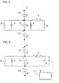
- Figure 3 shows a block diagram of an individual arrangement of safety device, according to the invention, in an assembly where this arrangement has an internal order.
- Figure 4 shows a block diagram of an individual arrangement of safety device, according to the invention, in an assembly where this device is controlled by a mixed control set.
- each module may consist of an accumulator electric or a group of electric accumulators and for example a group of "p" identical accumulators mounted in parallel.
- Each module is provided equipped with an individual arrangement of device security, as shown schematically in Figure 1, for module 1 '.
- the layout presented comprises two branch circuits which are connected in parallel to two end terminals of a module in the battery, i.e. at terminals 2 'and 2 ". module 1 '.
- a first of the two branch circuits has a member consumer of electrical energy, such as a dissipation resistor energy 3, in series with a switching member 4, for example of the type bistable.
- This first circuit is designed to be able to be put into service by action on the switching member 4 so as to make it pass and short-circuit the terminals 2 'and 2 "of module 1', through the consumer unit 3, in all conditions and more particularly when the accumulator (s) of module 1 'are when loaded and possibly fully charged.
- the consumer organ 3 is therefore chosen according to the capacity of the module, so as to allow slow discharge of this module, with heat dissipation compatible with the battery environment and typically corresponding to a current equivalent to tenth or one hundredth of the value of the module capacity 1 '.
- the accumulator or the group of accumulators of this module is discharged in this way compared to other accumulators in the series assembly constituting the battery, as if its leakage current were increased by the current passing through the consumer organ 3.
- a trigger 5 for example with detection of the crossing of a value of upper voltage threshold V1 by the voltage across the terminals of module 1 '.
- the switching device and the trigger can be combined so that the first branch circuit operates autonomously. They can also optionally be separated and the switching member can be controlled via an external programmed control unit.
- the second of the two safety device bypass circuits presented in FIG. 1, includes a switching member 6, for example of the type single shot and therefore irreversible change of state, allowing directly short-circuit terminals 2 'and 2 "of module 1', when switched conductor from a state where it is not passing.
- the driver state command of the switching member 6 is here assumed to be triggered, by a trigger 7, for example detection of crossing of a lower voltage threshold value V2 by the voltage across the terminals of module 1 ', so as to create a short circuit intended to be final between these boundaries. It is of course conceivable that the triggers 5 and 7 are combined.
- the second branch circuit is then put into service, during a second phase, when the voltage across the module 1 'is down to the value V2, under the action of the first circuit, to allow a short circuit direct and permanent between these terminals.
- the lower voltage threshold value V2 is determined, in a conventional manner for those skilled in the art, so as to authorize such a short-circuiting without risk, it is for example chosen to around 2.5 volts in the case of an accumulator in Lithium-ion technology.
- the invention is alternatively provided to obtain a short circuit internally between terminals of a faulty module, continuing to discharge this module via the first branch circuit associated with it up to the electrical continuity between terminals of a module from the moment the voltage at terminals of this module has exceeded the upper voltage threshold value V1.
- This discharge is then continued via this first branch circuit, up to an inversion of the polarity which corresponds to a negative threshold of the voltage present at the terminals of the module and which is obtained when the battery is at again requested to discharge. This then has very low resistance internal through which it is definitively short-circuited.
- the switching member 4 is possibly a relay.
- This relay is calibrated to be able to support the current what is likely to provide the module 1 'through the resistor 3, in case of serious failure for which the voltage across the module exceeds the value upper threshold V1. Resistor 3 is, of course, also calibrated for the same reason.
- the relay which constitutes the switching member 4 is controlled by a control unit programmed 8 external to the safety device, as symbolized by the L1 link.
- This programmed control unit 8 is for example of the logic unit type, organized around a processor with memories and at least one interface, by which is received a voltage value information V taken from the terminals of the module 1 '. She commands, according to a determined program and in a way successive, the switching member 4 of the first branch circuit and the switching 6 of the second branch circuit.
- Such a control unit duly programmed, possibly allows to implement different control programs for the organs of switching. It is in particular possible to control the switching member 4 in a different way from that indicated above, in order to be able to reduce it to a position of interruption from the position where he is conducting and for which a current through resistor 3, due to the presence at the terminals of module 1 ' of a voltage V greater than V1, if the voltage V drops for a prolonged period below V1.
- At least one of the switching devices, here references 4 ', 6', of the safety device is a thermosensitive element which passes from a non-conducting state to a conducting state, when heated.
- heat-sensitive elements irreversibly change to a conductive state from a non-conductive state, when heated above a determined minimum threshold temperature.
- the trigger 5 ' which is connected to the terminals of the module 1', is assumed here consisting of a plurality of diodes connected in series and placed so as to heating the thermosensitive element which constitutes the switching member 4 '.
- This trip unit operates when the voltage V between terminal 2 "and terminal 2 'is greater than the upper threshold value V1.
- the serial assembly of the diodes possibly associated with a series resistor, not shown, is made of manner known to those skilled in the art so as to produce heating sufficient to switch the switching member 4 'under these conditions.
- the trigger 7 ' which is also connected to the terminals of the module 1', is here supposed to consist of a single diode mounted in opposite direction to the diodes in series of the trigger 5 ', that is to say with its cathode connected to the terminal 2' and its anode connected to terminal 2 ".
- This single diode is placed so as to heat the thermosensitive element which constitutes the switching member 6 'so as to switch when the voltage V between terminals 2 "and 2 'drops below the value lower threshold V2.
- the safety device thus produced can therefore be entirely autonomous in its operation.
- the safety device comprises a switching member 4 of the first branch circuit which is controlled by a control unit 8 external to the safety device, as in the exemplary embodiment presented in FIG. 2, this command also being here symbolized by an L1 link.
- the second branch circuit is planned equipped with a 6 'switching device, of the thermosensitive element type, controlled by means of a heating trigger 7 ′, constituted by a diode, according to a assembly corresponding to that envisaged for the second branch circuit, in connection with FIG. 3.
- each of the modules in series, of one or more electric accumulators, that includes a battery with a safety device to short-circuit it individually in the event of failure, as envisaged above.
Landscapes
- Engineering & Computer Science (AREA)
- Power Engineering (AREA)
- Charge And Discharge Circuits For Batteries Or The Like (AREA)
- Connection Of Batteries Or Terminals (AREA)
- Secondary Cells (AREA)
- Protection Of Static Devices (AREA)
Applications Claiming Priority (2)
| Application Number | Priority Date | Filing Date | Title |
|---|---|---|---|
| FR9916330A FR2803123B1 (fr) | 1999-12-23 | 1999-12-23 | Dispositif de securite pour batterie d'accumulateurs electriques et batterie equipee de ce dispositif |
| FR9916330 | 1999-12-23 |
Publications (2)
| Publication Number | Publication Date |
|---|---|
| EP1111751A1 true EP1111751A1 (de) | 2001-06-27 |
| EP1111751B1 EP1111751B1 (de) | 2008-02-13 |
Family
ID=9553702
Family Applications (1)
| Application Number | Title | Priority Date | Filing Date |
|---|---|---|---|
| EP00403521A Expired - Lifetime EP1111751B1 (de) | 1999-12-23 | 2000-12-14 | Schutzvorrichtung für Batteriezellen und Batterie mit einer solchen Vorrichtung |
Country Status (5)
| Country | Link |
|---|---|
| US (1) | US6741437B2 (de) |
| EP (1) | EP1111751B1 (de) |
| JP (1) | JP2001236997A (de) |
| DE (1) | DE60038000T2 (de) |
| FR (1) | FR2803123B1 (de) |
Cited By (3)
| Publication number | Priority date | Publication date | Assignee | Title |
|---|---|---|---|---|
| CN102668307A (zh) * | 2009-10-21 | 2012-09-12 | K2能源解决方案有限公司 | 用于平衡串联连接的电池单元的充电的电路 |
| US10974606B2 (en) | 2016-08-31 | 2021-04-13 | Cps Technology Holdings Llc | Bi-stable relay |
| US20220368137A1 (en) * | 2021-05-17 | 2022-11-17 | Fortune Electric Co., Ltd. | Online reconfigurable battery system with current surge protection modules and activation method thereof |
Families Citing this family (11)
| Publication number | Priority date | Publication date | Assignee | Title |
|---|---|---|---|---|
| JP3766069B2 (ja) * | 2003-03-31 | 2006-04-12 | 株式会社東芝 | 燃料電池保護回路、燃料電池保護方法および燃料電池 |
| WO2005008266A1 (en) | 2003-07-09 | 2005-01-27 | Premium Power Corporation | Device for monitoring and charging of a selected group of battery cells |
| US7342768B2 (en) * | 2004-02-17 | 2008-03-11 | Cooper Technologies Company | Active balancing modular circuits |
| FR2877499B1 (fr) * | 2004-10-28 | 2007-01-26 | Eads Astrium Sas Soc Par Actio | Procede de gestion d'une batterie rechargeable et batterie rechargeable adaptee pour mettre en oeuvre ce procede |
| CN100373685C (zh) * | 2005-09-13 | 2008-03-05 | 程浩川 | 内嵌有电流取样电阻的单体水平铅酸蓄电池 |
| US7852047B2 (en) * | 2007-09-20 | 2010-12-14 | Denso Corporation | Disconnection detection device of assembled battery system and disconnection detection method of same |
| FR2951320B1 (fr) | 2009-10-08 | 2011-12-30 | Vehicules Electr Soc D | Batterie electrique comprenant une pluralite d'elements generateurs d'energie electrique |
| CN103311897A (zh) * | 2012-03-06 | 2013-09-18 | 北京联动天翼科技有限公司 | 锂电池电芯安全性的提高装置 |
| GB2504931A (en) * | 2012-08-13 | 2014-02-19 | Energy Control Ltd | Secondary Battery Pack formed by bridge connection of secondary battery cells and fuses |
| GB2505426A (en) * | 2012-08-29 | 2014-03-05 | Energy Control Ltd | Secondary battery pack formed by bridge connection of two secondary battery cells and two fuses. |
| DE102015205153A1 (de) * | 2015-03-23 | 2016-09-29 | Robert Bosch Gmbh | Schutzschaltung zum Ladungsausgleich von Batteriezellen einer Batterie sowie Batteriezelle |
Citations (2)
| Publication number | Priority date | Publication date | Assignee | Title |
|---|---|---|---|---|
| EP0515024A2 (de) * | 1991-05-23 | 1992-11-25 | Space Systems / Loral, Inc. | Vorrichtung mit Bypass-Schaltkreis |
| US5258244A (en) * | 1991-12-09 | 1993-11-02 | Hughes Aircraft Company | Reversible automatic cell bypass circuit |
Family Cites Families (10)
| Publication number | Priority date | Publication date | Assignee | Title |
|---|---|---|---|---|
| US4713597A (en) * | 1985-12-04 | 1987-12-15 | Powerplex Technologies, Inc. | Silicon diode looping element for protecting a battery cell |
| US5180641A (en) * | 1991-05-09 | 1993-01-19 | Rockwell International Corporation | Battery cell bypass circuit |
| JP3331529B2 (ja) * | 1993-01-29 | 2002-10-07 | キヤノン株式会社 | 蓄電装置及び電力システム |
| JP3002623B2 (ja) * | 1993-12-03 | 2000-01-24 | 富士電気化学株式会社 | 直列電池の過放電防止回路、過充電防止回路および充放電制御回路 |
| JP3421519B2 (ja) * | 1996-02-13 | 2003-06-30 | 三洋電機株式会社 | 過充電防止回路、過放電防止回路及び充放電制御回路 |
| JPH11191436A (ja) * | 1997-12-26 | 1999-07-13 | Hitachi Ltd | 蓄電保護器 |
| US5898239A (en) * | 1998-01-26 | 1999-04-27 | Lockhead Martin Corp. | Automatic electronic bypass power switch |
| US6139998A (en) * | 1998-03-23 | 2000-10-31 | Konica Corporation | Transparent substrate for an electrophotographic photoreceptor and an electrophotographic photoreceptor using the same |
| JPH11346443A (ja) * | 1998-06-02 | 1999-12-14 | Hitachi Ltd | 蓄電装置用組電池制御装置 |
| US6087035A (en) * | 1998-10-19 | 2000-07-11 | Hughes Electronics Corporation | Low-voltage-drop diode bypass of failed battery cell |
-
1999
- 1999-12-23 FR FR9916330A patent/FR2803123B1/fr not_active Expired - Fee Related
-
2000
- 2000-12-14 DE DE60038000T patent/DE60038000T2/de not_active Expired - Fee Related
- 2000-12-14 EP EP00403521A patent/EP1111751B1/de not_active Expired - Lifetime
- 2000-12-19 US US09/739,386 patent/US6741437B2/en not_active Expired - Fee Related
- 2000-12-21 JP JP2000388441A patent/JP2001236997A/ja active Pending
Patent Citations (2)
| Publication number | Priority date | Publication date | Assignee | Title |
|---|---|---|---|---|
| EP0515024A2 (de) * | 1991-05-23 | 1992-11-25 | Space Systems / Loral, Inc. | Vorrichtung mit Bypass-Schaltkreis |
| US5258244A (en) * | 1991-12-09 | 1993-11-02 | Hughes Aircraft Company | Reversible automatic cell bypass circuit |
Cited By (5)
| Publication number | Priority date | Publication date | Assignee | Title |
|---|---|---|---|---|
| CN102668307A (zh) * | 2009-10-21 | 2012-09-12 | K2能源解决方案有限公司 | 用于平衡串联连接的电池单元的充电的电路 |
| US10974606B2 (en) | 2016-08-31 | 2021-04-13 | Cps Technology Holdings Llc | Bi-stable relay |
| US11990776B2 (en) | 2016-08-31 | 2024-05-21 | Cps Technology Holdings Llc | Bi-stable relay |
| US20220368137A1 (en) * | 2021-05-17 | 2022-11-17 | Fortune Electric Co., Ltd. | Online reconfigurable battery system with current surge protection modules and activation method thereof |
| US11862999B2 (en) * | 2021-05-17 | 2024-01-02 | Fortune Electric Co., Ltd. | Online reconfigurable battery system with current surge protection modules and activation method thereof |
Also Published As
| Publication number | Publication date |
|---|---|
| EP1111751B1 (de) | 2008-02-13 |
| US6741437B2 (en) | 2004-05-25 |
| DE60038000T2 (de) | 2009-02-12 |
| DE60038000D1 (de) | 2008-03-27 |
| FR2803123A1 (fr) | 2001-06-29 |
| US20010006747A1 (en) | 2001-07-05 |
| FR2803123B1 (fr) | 2002-03-15 |
| JP2001236997A (ja) | 2001-08-31 |
Similar Documents
| Publication | Publication Date | Title |
|---|---|---|
| EP1111751B1 (de) | Schutzvorrichtung für Batteriezellen und Batterie mit einer solchen Vorrichtung | |
| EP2452384B1 (de) | Verlustarmer akkumulator | |
| EP2629385B1 (de) | Energiespeicherkette für Fahrzeug, die mindestens ein Modul mit Superkondensatoren umfasst, Energiespeichersystem, das eine solche Kette umfasst, und Schienenfahrzeug, das ein solches System umfasst | |
| EP1764891B1 (de) | Elektronische Auslösevorrichtung mit Überwachungsmittel und entsprechendes Überwachungsverfahren | |
| CH676067A5 (de) | ||
| WO2012004488A1 (fr) | Convertisseur statique avec structure redondante | |
| WO1999031778A1 (fr) | Dispositif de protection contre des surintensites, notamment pour la protection rearmable d'un interrupteur controle | |
| EP0224535B1 (de) | Statischer schalter oder schaltgerät zur geschützten versorgung einer last und ihrer leitung | |
| EP3437115B1 (de) | Hybridisierungsystem für hochspannungsgleichstrom | |
| FR2770050A1 (fr) | Dispositif de securite d'un accumulateur electrochimique | |
| CA2406449A1 (fr) | Dispositif anti-points chauds pour module photovoltaique et module photovoltaique equipe d'un tel dispositif | |
| EP4430715A1 (de) | Gleichstrom-kurzschluss-stromverstärker | |
| FR2938710A1 (fr) | Dispositif de contournement electrique | |
| WO2018167306A1 (fr) | Systeme d'alimentation en energie electrique d'un reseau de bord d'un sous-marin | |
| EP4020755A1 (de) | Isoliervorrichtung und -verfahren für stromakkumulator | |
| EP4485496B1 (de) | Elektrische schutzvorrichtung | |
| EP1162470A1 (de) | Isolationsüberwachungstestvorrichtung für elektrische Netze | |
| CA3060084C (fr) | Systeme d'hybridation pour courant continu haute tension | |
| WO2024246167A1 (fr) | Unité de stockage d'énergie électrique | |
| EP3476018A1 (de) | Verfahren zur erzeugung eines kurzschlussstroms zum auslösen eines elektrischen schutzelements | |
| FR3164845A1 (fr) | Système de protection d’une batterie et batterie | |
| WO2024246163A1 (fr) | Unité de stockage d'énergie électrique | |
| FR2959631A1 (fr) | Systeme de deconnexion pour batterie | |
| FR3041827B1 (fr) | Dispositif electronique de connexion/deconnexion pour batterie a haute-tension et procede associe | |
| FR3137225A1 (fr) | Dispositif et procédé d’isolement d’accumulateur électrique à réserve de matière conductrice fusible |
Legal Events
| Date | Code | Title | Description |
|---|---|---|---|
| PUAI | Public reference made under article 153(3) epc to a published international application that has entered the european phase |
Free format text: ORIGINAL CODE: 0009012 |
|
| AK | Designated contracting states |
Kind code of ref document: A1 Designated state(s): DE FR GB |
|
| AX | Request for extension of the european patent |
Free format text: AL;LT;LV;MK;RO;SI |
|
| 17P | Request for examination filed |
Effective date: 20011227 |
|
| AKX | Designation fees paid |
Free format text: DE FR GB |
|
| RAP1 | Party data changed (applicant data changed or rights of an application transferred) |
Owner name: SAFT FINANCE S.AE.R.L. |
|
| GRAP | Despatch of communication of intention to grant a patent |
Free format text: ORIGINAL CODE: EPIDOSNIGR1 |
|
| GRAS | Grant fee paid |
Free format text: ORIGINAL CODE: EPIDOSNIGR3 |
|
| GRAA | (expected) grant |
Free format text: ORIGINAL CODE: 0009210 |
|
| AK | Designated contracting states |
Kind code of ref document: B1 Designated state(s): DE FR GB |
|
| REG | Reference to a national code |
Ref country code: GB Ref legal event code: FG4D Free format text: NOT ENGLISH |
|
| REF | Corresponds to: |
Ref document number: 60038000 Country of ref document: DE Date of ref document: 20080327 Kind code of ref document: P |
|
| RAP2 | Party data changed (patent owner data changed or rights of a patent transferred) |
Owner name: SAFT GROUPE SA |
|
| PLBE | No opposition filed within time limit |
Free format text: ORIGINAL CODE: 0009261 |
|
| STAA | Information on the status of an ep patent application or granted ep patent |
Free format text: STATUS: NO OPPOSITION FILED WITHIN TIME LIMIT |
|
| 26N | No opposition filed |
Effective date: 20081114 |
|
| REG | Reference to a national code |
Ref country code: FR Ref legal event code: TP Ref country code: FR Ref legal event code: CA |
|
| PGFP | Annual fee paid to national office [announced via postgrant information from national office to epo] |
Ref country code: FR Payment date: 20081212 Year of fee payment: 9 |
|
| PGFP | Annual fee paid to national office [announced via postgrant information from national office to epo] |
Ref country code: DE Payment date: 20081219 Year of fee payment: 9 |
|
| REG | Reference to a national code |
Ref country code: GB Ref legal event code: 732E Free format text: REGISTERED BETWEEN 20090528 AND 20090603 |
|
| PGFP | Annual fee paid to national office [announced via postgrant information from national office to epo] |
Ref country code: GB Payment date: 20081216 Year of fee payment: 9 |
|
| GBPC | Gb: european patent ceased through non-payment of renewal fee |
Effective date: 20091214 |
|
| REG | Reference to a national code |
Ref country code: FR Ref legal event code: ST Effective date: 20100831 |
|
| PG25 | Lapsed in a contracting state [announced via postgrant information from national office to epo] |
Ref country code: FR Free format text: LAPSE BECAUSE OF NON-PAYMENT OF DUE FEES Effective date: 20091231 |
|
| PG25 | Lapsed in a contracting state [announced via postgrant information from national office to epo] |
Ref country code: DE Free format text: LAPSE BECAUSE OF NON-PAYMENT OF DUE FEES Effective date: 20100701 |
|
| PG25 | Lapsed in a contracting state [announced via postgrant information from national office to epo] |
Ref country code: GB Free format text: LAPSE BECAUSE OF NON-PAYMENT OF DUE FEES Effective date: 20091214 |