EP1111373A2 - Verfahren zur optischen und spektroskopischen Messung der Eigenschaften von festen Materialien und zugehörige Anordnung - Google Patents
Verfahren zur optischen und spektroskopischen Messung der Eigenschaften von festen Materialien und zugehörige Anordnung Download PDFInfo
- Publication number
- EP1111373A2 EP1111373A2 EP00127155A EP00127155A EP1111373A2 EP 1111373 A2 EP1111373 A2 EP 1111373A2 EP 00127155 A EP00127155 A EP 00127155A EP 00127155 A EP00127155 A EP 00127155A EP 1111373 A2 EP1111373 A2 EP 1111373A2
- Authority
- EP
- European Patent Office
- Prior art keywords
- measurement
- light
- arrangement
- specular
- arrangement according
- Prior art date
- Legal status (The legal status is an assumption and is not a legal conclusion. Google has not performed a legal analysis and makes no representation as to the accuracy of the status listed.)
- Withdrawn
Links
Images


Classifications
-
- G—PHYSICS
- G01—MEASURING; TESTING
- G01N—INVESTIGATING OR ANALYSING MATERIALS BY DETERMINING THEIR CHEMICAL OR PHYSICAL PROPERTIES
- G01N21/00—Investigating or analysing materials by the use of optical means, i.e. using sub-millimetre waves, infrared, visible or ultraviolet light
- G01N21/17—Systems in which incident light is modified in accordance with the properties of the material investigated
- G01N21/47—Scattering, i.e. diffuse reflection
- G01N21/4738—Diffuse reflection, e.g. also for testing fluids, fibrous materials
-
- G—PHYSICS
- G01—MEASURING; TESTING
- G01N—INVESTIGATING OR ANALYSING MATERIALS BY DETERMINING THEIR CHEMICAL OR PHYSICAL PROPERTIES
- G01N21/00—Investigating or analysing materials by the use of optical means, i.e. using sub-millimetre waves, infrared, visible or ultraviolet light
- G01N21/17—Systems in which incident light is modified in accordance with the properties of the material investigated
- G01N21/55—Specular reflectivity
Definitions
- the invention relates to a method for optical and spectroscopic detection of properties of solid Materials according to the preamble of claim 1.
- the invention also relates to an associated one Order to carry out the method.
- I have spectroscopy in various fields of Technology as a sensor, proven for quality control, for example. Thereby, after interaction of optical radiation in the given wavelength range with materials Response signals recorded and evaluated.
- wood chips or waste paper bales as raw materials for paper production or also deliver paper webs during production specific spectra used for different purposes can be.
- the measurement objects z. B as bulk goods, that passes the sensor is changing during the measurement the distance between sensor and measurement object and / or locally all the time.
- Optical and spectroscopic methods capture through the Interaction of light with the surface through the selective Absorption the chemical composition and by the Measurement of the scattered light including morphological variations. Watched the phase relationships are also determined by a suitable arrangement of the waves among themselves, so you can use the (also spectral) interferences also statements z. B. about the Make layer thickness of surface layers.
- optical and spectroscopic methods are special suitable as on-line and in-line measurement techniques because they work very quickly and without contact. This turns light known spectral distribution in the wavelength range 0.2 ⁇ m up to 30 ⁇ m on the sample and the reflected light analyzed.
- Another way to solve the problem is in a representative sampling and a subsequent one external homogenization.
- the task is according to the invention with regard to the measuring method through a process of optical and spectroscopic Measurement of the properties of solid materials according to claim 1 solved.
- the task according to the invention by an arrangement for optical and spectroscopic Measurement of the properties of solid materials solved according to claim 6.
- Advantageous configurations are in each case Subject of further claims.
- the arrangement according to claim 6 comprises an optical device for the irradiation of light on the material surface and to detect the light after interaction with the material surface and a spectrometer to evaluate the received light.
- a focus-tolerant measuring geometry is also in the event of a temporal and / or local change of the Distance of the material surface a measurement is possible.
- Geometric measuring arrangements are created by the invention, which allow the diffuse parts to be significantly different separate the specular parts of the reflected light.
- geometric solutions can be achieved with the invention can be realized that allow it, even outside the focus level the desired ones without tracking the optics to get correct information.
- flutter tolerance in technical jargon of a so-called flutter amplitude or flutter tolerance spoken.
- the flutter tolerance in an apparatus is that Amplitude (or tolerance) that allows the meter or to move the substrate in one direction without the Information content of the reflected light changes.
- Arrangement is determined by measuring the spectral Interference in an arrangement 45R45 (45 ° illumination angle, 45 ° detection angle) z. B. in a film 1, the layer thickness d measure a coating on-line.
- the slide 1 will for this purpose irradiated with light from a source 2 (lamp).
- the Light reflected by the film 1 is detected by a detector 3 detected. Due to the belt speed it happens that the film 1 flutters, d. H. out of focus F the geometric measuring arrangement moves. Still, that should Layer thickness d from the data of the reflected light beyond doubt can be determined.
- wood chips are used 4 spectrally characterized on-line on the conveyor belt (Art of the wood, moisture, age, lignin content etc.). Important is the measurement of the diffuse reflection, because only here the chemical and morphological parameters play a role. However, depending on the location of the chips 4 become the detector different proportions of specular light with less Preserve depth interaction and diffuse reflection. Shown is an arrangement 0R0 (i.e. illuminated at 0 ° angle and in 0 ° angle detected) or diffuseRdiffuse. The flutter amplitude is defined here by the tolerance of the measuring arrangement, where the variation in the height and size of the wood chips 4 doesn't matter. Outside of this range, the Information, among other things, due to specular proportions disturbed.
- Typical geometric arrangements for the measurement of the specular reflected light are 0R0 and especially 45R45 arrangements. These arrangements are used in industry, to measure reflecting surfaces.
- a flutter tolerance can be generated by making the lighting spot essential is larger than the detection spot (or vice versa). An even clearer assignment can be obtained if at the same time Polarized light is used and the lighting and the detection takes place with the same polarization. requirement for this arrangement is that the lighting is true to color over the entire lighting spot. In order to flutter amplitudes can be realized in the centimeter range.
- Rough surfaces have due to the distribution of the elementary levels both specular and diffuse reflection components, with the proportions of diffuse and directional reflection are different.
- a goniometric arrangement is used the spectrometer ("spectral goniometry" e.g. 45R45 with 45R0 with 45R0 on the side etc.) and thus covers the room distributes the specular with different weights and diffuse parts.
- spectral goniometry e.g. 45R45 with 45R0 with 45R0 on the side etc.
- specular from the diffuse parts separate their behavior with polarized Light. Specularly reflected light keeps reflecting the polarity while diffused light due to the scatter the polarization loses.
- polarizers By measuring each with parallel and crossed (other angles possible) polarizers the individual parts can be determined in this way.
- FIG 3 is an example of the separation separation from specular and diffuse fractions by using a polarizing Beam splitter 10 shown.
- the polarizing one Beam splitter 10 is in the illustrated embodiment as Wollaston prism. That emitted from a light source 2 After passing through a polarizer, light is 5 polarized accordingly. The polarized light hits a mirror 6 and is applied to the sample 8 by a lens 7 focused. The light is reflected by the measurement object 8 (sample) and is over the lens 7 and another lens 9 in led the Wollaston prism 10.
- Wollaston prism 10 polarizing Beam splitter
- the light is split and Spectrometers 11 and 12 supplied for spectral analysis.
- the scattering centers of which are geometric Have dimensions that are much larger than the wavelength of light are becoming specular proportions be present in the reflected light.
- Aim of a measurement the diffuse reflection in which the morphological and chemical parameters are included, is the blanking of the specular portion through a suitable arrangement of the measurement geometry.
- the main focus of the development is on achieving one large flutter tolerance that is necessary, even bulk goods online to measure. While the previous orders one Flutter amplitude of about 1 cm, the possibilities are with a measuring head in 0R0 arrangement much higher.
- the intensity of the emitted light from a source 2 decreases with the square of the distance.
- the area of the light spot AL increases with the square of the distance. That is, that the light intensity of sample 8 as a light source always has the same absolute value regardless of the distance to the light source 2.
- F is again in each case in FIGS referred to the focus of the measuring arrangement.
- the light guide 13 of the detector 2 has a specific one Opening angle at which he can receive or emit light can.
- This so-called optical aperture is at the usual arrangements about +/- 14 °.
- the opening angle ⁇ L of the light source 2 and the angle ⁇ S of the shadow, which the light guide 13 generates, are present. This is determined by the distance of the light guide 13 from the light source 2 and the geometric dimensions of the element that creates the shadow.
- the flutter amplitude is in principle infinitely large, since only diffuse light or light illuminated by diffraction interference is captured by the measurement object 8.
- the geometry is arranged in such a way that the detector spot A D has a larger opening angle ⁇ D than the shadow and thus a crossing point is created in the geometry.
- different proportions of specular light can thus be reflected, which can be eliminated by the measures as described above. Due to the oblique angle of incidence, a measurement with a larger flutter amplitude is normally still possible.
- FIG. 5 show that a large active zone Z A is formed, in which the measurement can take place without disturbing the specular component if the opening angle ⁇ D of the detector 3 is small compared to the shadow angle ⁇ S.
- This geometry can also be achieved by using integrated Realize light guides, e.g. B. by concentric Arrangement of detector and exposure light guide with different or identical opening angles.
- the positioning of the reference measurement prepares difficulties with the usual on-line applications because it cannot normally be assumed that the Reference measurement or the calibration measurement in focus F of the geometric Measurement arrangement (i.e. in the sample plane) take place can.
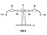
- the measuring arrangement shown above therefore allows another new way to make reference measurements without problems to integrate into the online measurement. 6 to 8 are therefore shown measurement arrangements that allow the Integrate reference measurement in the beam path 14 without thereby disrupting the sample plane.
- a suitable deflecting mirror for example a mirrored one Prism 17
- can also be multiple detectors e.g. B. two detectors 3a and 3b, attach (measuring arrangement according to FIG 8).
- the beam path of the two detectors 3a and 3b is designated 15a and 15b.
- a lens 18 in the beam path 15 of the detector 3 (FIG 7) the opening angle can also be adjusted in certain areas vary.
- the reference measurement can be made in the measuring arrangement according to FIG 7 very simple design by the back or top of the Deflecting mirror 16 is used for this. You can with the Coat reference substance. Then enough for the reference measurement an electric rotating magnet that the deflection mirror 16 by 90 ° turns. The detector 3 then sees the illuminated back of the reference the deflecting mirror 16.
- Light source 2 sits, can optics to adjust the Insert detector angle.
Landscapes
- Physics & Mathematics (AREA)
- Health & Medical Sciences (AREA)
- Life Sciences & Earth Sciences (AREA)
- Chemical & Material Sciences (AREA)
- Analytical Chemistry (AREA)
- Biochemistry (AREA)
- General Health & Medical Sciences (AREA)
- General Physics & Mathematics (AREA)
- Immunology (AREA)
- Pathology (AREA)
- Investigating Or Analysing Materials By Optical Means (AREA)
Abstract
Description
- FIG 1
- eine Anordnung zur Messung der spektralen Interferenz bei einer Folie.
- FIG 2
- eine Anordnung zur Messung der spektralen Interferenz bei Hackschnitzeln,
- FIG 3
- eine Anordnung mit einem polarisierenden Stahlteiler,
- FIG 4
- Schattenfleck und Beleuchtungsfleck einer Standardanordnung,
- FIG 5
- die aktive Zone bei zwei verschiedenen Detektorwinkeln,
- FIG 6
- eine Anordnung mit Lampenspiegel,
- FIG 7
- eine Anordnung mit Detektorspiegel,
- FIG 8
- eine Anordnung mit Prisma.
- Abschirmung des spekularen Lichts,
- Ausgleich der Intensitätsveränderung des Signals,
- diffuse Beleuchtung des Messobjekts 8 durch Beugungsinterferenz
- Lichtleiter starker Licht- und Wärmebelastung ausgesetzt,
- keine Veränderung der Detektoroptik vor dem Lichtleiter möglich,
- Referenzmessung nur mit Schlitten- oder Schwenkbewegung möglich,
- kleinster Lichtleiterradius x durch die Mechanik des Lichtleiters festgelegt.
- kleiner Schatten möglich,
- Lichtquelle 2 in horizontaler Stellung,
- keine Licht- und Wärmebelastung des Lichtleiters 13,
- Einsatz von Linsen vor dem Detektor 3 möglich.
- Aufwendige optische Justage nötig,
- Energieverluste am Umlenkspiegel 16,
- Schatten ist nicht mittig im Leuchtfleck,
- Umlenkspiegel 16 kann chromatische Effekte erzeugen,
- Umlenkspiegel 16 kann verschmutzten,
- Referenz nur mit Schlitten- oder Schwenkbewegung möglich.
Claims (12)
- Verfahren zur Erfassung von Eigenschaften von Materialien durch spektroskopische Messungen, wobei sich während der Messung der Abstand der Materialoberfläche zeitlich und/oder örtlich ändert ("out-of-focus-Lage"),
dadurch gekennzeichnet,
dass bei der spektroskopischen Messung gleichermaßen die spekulare und die diffuse Reflexion an der Materialoberfläche erfasst wird und dass in der Detektion und der Messwertverarbeitung eine eindeutige Trennung der Information von spekularer und diffuser Reflexion vorgenommen wird. - Verfahren nach Anspruch 1,
dadurch gekennzeichnet,
dass fokustolerante Messgeometrien verwendet werden. - Verfahren nach Anspruch 1 oder Anspruch 2,
gekennzeichnet durch spektroskopische Messungen an Holzhackschnitzeln. - Verfahren nach Anspruch 1 oder Anspruch 2,
gekennzeichnet durch spektroskopische Messungen an Altpapierballen. - Verfahren nach Anspruch 1 oder Anspruch 2,
gekennzeichnet durch spektroskopische Messungen an laufenden Materialbahnen, insbesondere Papierbahnen oder Metallbändern. - Anordnung zur Durchführung des Verfahrens nach Anspruch 1 oder einem der Ansprüche 2 bis 5, mit einer optischen Einrichtung zur Einstrahlung von Licht auf die Materialoberfläche und zur Erfassung des Lichts nach Wechselwirkung mit der Materialoberfläche sowie einem Spektrometer zur Auswertung des empfangenen Lichts, gekennzeichnet
durch eine fokustolerante Messgeometrie. - Anordnung nach Anspruch 5,
dadurch gekennzeichnet,
dass Mittel zur Abschirmung des spekularen Lichtes vorhanden sind. - Anordnung nach Anspruch 5,
dadurch gekennzeichnet,
dass Mittel zum Ausgleich der Intensitätsveränderung des Signals vorhanden sind. - Anordnung nach Anspruch 6,
dadurch gekennzeichnet,
dass die Messgeometrie Mittel zur diffusen Beleuchtung enthält. - Anordnung nach Anspruch 6,
dadurch gekennzeichnet,
dass die diffuse Beleuchtung durch Ausnutzung der Beugungsinterferenz am Schattenbildner erfolgt. - Anordnung nach Anspruch 6,
dadurch gekennzeichnet,
dass in der fokustoleranten Messgeometrie der Abstand Beleuchtung/Detektor und Messobjekt groß gewählt ist, womit die Flatteramplitude klein wird im Vergleich zum Beleuchtung/Detektorabstand. - Anordnung nach Anspruch 11,
dadurch gekennzeichnet,
dass die Messgeometrie so gewählt ist, dass die Referenzmessung in den Strahlengang integriert ist, wobei weder das Objekt noch die Messanordnung entfernt werden muss.
Applications Claiming Priority (2)
| Application Number | Priority Date | Filing Date | Title |
|---|---|---|---|
| DE19962428A DE19962428A1 (de) | 1999-12-22 | 1999-12-22 | Verfahren zur optischen und spektroskopischen Messung der Eigenschaften von festen Materialien und zugehörige Einrichtung |
| DE19962428 | 1999-12-22 |
Publications (2)
| Publication Number | Publication Date |
|---|---|
| EP1111373A2 true EP1111373A2 (de) | 2001-06-27 |
| EP1111373A3 EP1111373A3 (de) | 2002-05-02 |
Family
ID=7934106
Family Applications (1)
| Application Number | Title | Priority Date | Filing Date |
|---|---|---|---|
| EP00127155A Withdrawn EP1111373A3 (de) | 1999-12-22 | 2000-12-12 | Verfahren zur optischen und spektroskopischen Messung der Eigenschaften von festen Materialien und zugehörige Anordnung |
Country Status (2)
| Country | Link |
|---|---|
| EP (1) | EP1111373A3 (de) |
| DE (1) | DE19962428A1 (de) |
Cited By (2)
| Publication number | Priority date | Publication date | Assignee | Title |
|---|---|---|---|---|
| WO2011157319A1 (de) * | 2010-06-15 | 2011-12-22 | Wabco Gmbh | Sensor zur berührungslosen bestimmung der fahrbahnbeschaffenheit und dessen verwendung |
| US8582095B2 (en) | 2007-11-30 | 2013-11-12 | Buhler Ag | Spectrometer measuring head for analyzing characteristic variables of liquid, pasty or solid substances |
Family Cites Families (5)
| Publication number | Priority date | Publication date | Assignee | Title |
|---|---|---|---|---|
| US4022534A (en) * | 1976-03-23 | 1977-05-10 | Kollmorgen Corporation | Reflectometer optical system |
| US4661706A (en) * | 1985-02-25 | 1987-04-28 | Spectra-Tech Inc. | Blocker device for eliminating specular reflectance from a diffuse reflection spectrum |
| US5015100A (en) * | 1990-03-02 | 1991-05-14 | Axiom Analytical, Inc. | Apparatus and method for normal incidence reflectance spectroscopy |
| US5268749A (en) * | 1991-07-26 | 1993-12-07 | Kollmorgen Corporation | Apparatus and method for providing uniform illumination of a sample plane |
| DE59914046D1 (de) * | 1998-06-22 | 2007-01-25 | Siemens Ag | Verfahren zur Prozessführung und Prozessoptimierung bei der Herstellung von Fasermatten und/oder Faserplatten |
-
1999
- 1999-12-22 DE DE19962428A patent/DE19962428A1/de not_active Withdrawn
-
2000
- 2000-12-12 EP EP00127155A patent/EP1111373A3/de not_active Withdrawn
Cited By (4)
| Publication number | Priority date | Publication date | Assignee | Title |
|---|---|---|---|---|
| US8582095B2 (en) | 2007-11-30 | 2013-11-12 | Buhler Ag | Spectrometer measuring head for analyzing characteristic variables of liquid, pasty or solid substances |
| EP2215456B1 (de) * | 2007-11-30 | 2015-10-14 | Sentronic GmbH Gesellschaft für Optische Messsysteme | Spektrometermesskopf zur analyse von kenngrössen flüssiger, pastöser oder fester substanzen |
| WO2011157319A1 (de) * | 2010-06-15 | 2011-12-22 | Wabco Gmbh | Sensor zur berührungslosen bestimmung der fahrbahnbeschaffenheit und dessen verwendung |
| CN102939528A (zh) * | 2010-06-15 | 2013-02-20 | 威伯科有限公司 | 用于非接触式确定车道特性的传感器和其应用 |
Also Published As
| Publication number | Publication date |
|---|---|
| DE19962428A1 (de) | 2001-06-28 |
| EP1111373A3 (de) | 2002-05-02 |
Similar Documents
| Publication | Publication Date | Title |
|---|---|---|
| DE69416838T2 (de) | Vorrichtung zur spektralanalyse unter einer mehrzahl von winkeln | |
| DE2904787C2 (de) | Verfahren zur zerstörungsfreien Untersuchung einer Probe | |
| DE2852978C3 (de) | Vorrichtung zur spektroskopischen Bestimmung der Geschwindigkeit von in einer Flüssigkeit bewegten Teilchen | |
| EP0617273B1 (de) | Optisches Verfahren und Vorrichtung zur Analyse von Substanzen an Sensoroberflächen | |
| DE3240234C2 (de) | Oberflächenprofil-Interferometer | |
| DE10392315B4 (de) | Optische Konfiguration und Verfahren für differentielle Brechungskoeffizientenmessungen | |
| WO2001027591A2 (de) | Verfahren und vorrichtung zur charakterisierung einer kulturflüssigkeit | |
| DE69032110T2 (de) | Ellipsometrische Vorrichtung mit hohem Auflösungsvermögen | |
| DE2354141C2 (de) | Optisches Meßverfahren zum Untersuchen von Oberflächen und Einrichtung zur Durchführung des Verfahrens | |
| EP0011708A1 (de) | Verfahren und Vorrichtung zur Messung der Ebenheit, der Rauhigkeit oder des Krümmungsradius einer Messfläche | |
| EP2985579B1 (de) | Spektrometer mit monochromator und order-sorting-filter | |
| DE10154008C1 (de) | Verfahren und Anordnung zur spannungsoptischen Analyse von Festkörpern | |
| DE102009036383B3 (de) | Vorrichtung und Verfahren zur winkelaufgelösten Streulichtmessung | |
| DE10163657A1 (de) | Vorrichtung und Verfahren zur Untersuchung dünner Schichten | |
| DE4105192C2 (de) | Verfahren zum Bestimmen von Oberflächenrauhigkeiten und dergleichen | |
| DE60123996T2 (de) | Messung von oberflächendefekten | |
| DE69418505T2 (de) | Verfahren und Apparat zur Orientierungsbestimmung von Papierfasern | |
| WO2016015921A1 (de) | Messanordnung zur reflexionsmessung | |
| DE2103318B2 (de) | Streuhchtphotometer | |
| DE69120462T2 (de) | Infrarotfeuchtigkeitsmessgerät | |
| DE2306764A1 (de) | Mikroschwaerzungsmessverfahren und mikroschwaerzungsmesser bzw. mikrodensitometer | |
| DE4138679C2 (de) | Gerät zur Bestimmung visueller Oberflächeneigenschaften | |
| DE69005681T2 (de) | Transmissions-/Reflektionsdensitometer mit zwei Messköpfen. | |
| DE3214049A1 (de) | Spektralfluorometer | |
| EP3324149B1 (de) | Verfahren und vorrichtung zur bestimmung von oberflächenmodifikationen auf optisch transparenten bauteilen |
Legal Events
| Date | Code | Title | Description |
|---|---|---|---|
| PUAI | Public reference made under article 153(3) epc to a published international application that has entered the european phase |
Free format text: ORIGINAL CODE: 0009012 |
|
| AK | Designated contracting states |
Kind code of ref document: A2 Designated state(s): AT BE CH CY DE DK ES FI FR GB GR IE IT LI LU MC NL PT SE TR |
|
| AX | Request for extension of the european patent |
Free format text: AL;LT;LV;MK;RO;SI |
|
| PUAL | Search report despatched |
Free format text: ORIGINAL CODE: 0009013 |
|
| AK | Designated contracting states |
Kind code of ref document: A3 Designated state(s): AT BE CH CY DE DK ES FI FR GB GR IE IT LI LU MC NL PT SE TR |
|
| AX | Request for extension of the european patent |
Free format text: AL;LT;LV;MK;RO;SI |
|
| RIC1 | Information provided on ipc code assigned before grant |
Free format text: 7G 01N 21/55 A, 7G 01N 21/47 B |
|
| AKX | Designation fees paid | ||
| REG | Reference to a national code |
Ref country code: DE Ref legal event code: 8566 |
|
| STAA | Information on the status of an ep patent application or granted ep patent |
Free format text: STATUS: THE APPLICATION IS DEEMED TO BE WITHDRAWN |
|
| 18D | Application deemed to be withdrawn |
Effective date: 20021104 |