EP1111313A1 - Systèmes de fixation de lames - Google Patents
Systèmes de fixation de lames Download PDFInfo
- Publication number
- EP1111313A1 EP1111313A1 EP00403435A EP00403435A EP1111313A1 EP 1111313 A1 EP1111313 A1 EP 1111313A1 EP 00403435 A EP00403435 A EP 00403435A EP 00403435 A EP00403435 A EP 00403435A EP 1111313 A1 EP1111313 A1 EP 1111313A1
- Authority
- EP
- European Patent Office
- Prior art keywords
- rail
- support elements
- support
- blade
- engaged
- Prior art date
- Legal status (The legal status is an assumption and is not a legal conclusion. Google has not performed a legal analysis and makes no representation as to the accuracy of the status listed.)
- Granted
Links
- 239000003351 stiffener Substances 0.000 claims abstract description 7
- 238000009423 ventilation Methods 0.000 claims description 4
- 238000005253 cladding Methods 0.000 claims description 2
- XAGFODPZIPBFFR-UHFFFAOYSA-N aluminium Chemical compound [Al] XAGFODPZIPBFFR-UHFFFAOYSA-N 0.000 description 3
- 229910052782 aluminium Inorganic materials 0.000 description 3
- 238000003780 insertion Methods 0.000 description 2
- 230000037431 insertion Effects 0.000 description 2
- 230000004308 accommodation Effects 0.000 description 1
- 230000001419 dependent effect Effects 0.000 description 1
- PCHJSUWPFVWCPO-UHFFFAOYSA-N gold Chemical compound [Au] PCHJSUWPFVWCPO-UHFFFAOYSA-N 0.000 description 1
- 239000010931 gold Substances 0.000 description 1
- 229910052737 gold Inorganic materials 0.000 description 1
- 238000009434 installation Methods 0.000 description 1
- 238000003754 machining Methods 0.000 description 1
- 238000000034 method Methods 0.000 description 1
- 210000000056 organ Anatomy 0.000 description 1
Images

Classifications
-
- F—MECHANICAL ENGINEERING; LIGHTING; HEATING; WEAPONS; BLASTING
- F24—HEATING; RANGES; VENTILATING
- F24F—AIR-CONDITIONING; AIR-HUMIDIFICATION; VENTILATION; USE OF AIR CURRENTS FOR SCREENING
- F24F13/00—Details common to, or for air-conditioning, air-humidification, ventilation or use of air currents for screening
- F24F13/08—Air-flow control members, e.g. louvres, grilles, flaps or guide plates
- F24F13/082—Grilles, registers or guards
Definitions
- the present invention relates to a blade attachment system for mount the blades side by side so as to create an openwork structure.
- the blades are fixed parallel to each other at an angle to the wall on which they are installed.
- Such blades are used in particular to form ventilation grills closing a bay in a wall or to make siding of building walls.
- ventilation grilles the blades are kept at the inside of a frame mounted in the bay whereas in the case of a wall facing, the blades are placed on the fixing system and placed end to end to cover the Wall.
- stiffeners often aluminum, and support elements to be mounted on the stiffening profiles.
- a known technique consists in use stiffening profiles in which fixing notches are machined for the fixing the support elements. Therefore, each support member has a well determined location on the stiffening profile.
- Document GB-2 300 473 describes a system comprising a stiffening profile with a rail, support elements slidably engaged in the profile rail stiffener and blades fixed on the support elements.
- the sliding support in the profile rail is ensured by a shoe part which is engaged in the rail. This part therefore serves as means for retaining the support element. in the profile rail.
- the preamble of claim 1 is based on this document.
- the shoe part is directly part integral with the support element. Indeed, the shoe part forms a kind of sole of trapezoidal section from which extend the other flanges of the element support. It is therefore quite impossible to separate the shoe part from the rest of the support element.
- EP-0 770 832 describes a completely different type of grid, since the blades are inserted in the rail formed by the profile. However, as in the previous document, the part of the blade support means which are inserted in the rail are an integral part of the support means.
- the present invention aims to remedy the aforementioned drawbacks of the art by defining a more flexible fixing system with which the elements of support can be easily and quickly placed in the stiffener profile.
- the present invention provides a blade attachment system comprising the features set out in claim 1.
- the characterizing part of claim 1 states that the support elements are provided with means for reception adapted to receive the retaining members.
- retainers are not an integral part of the support elements, but on the contrary, they constitute separate elements reported in the reception means formed by the support elements.
- the retaining members are mounted on the elements of support at the level of adequate reception means.
- This feature allows the embodiment defined in a dependent claim, namely that the elements support can be inserted into the rail without the retainers which can be subsequently mounted on the support elements already engaged in the rail. This allows insert the support elements in the rail directly through the longitudinal opening and not from one end of the rail. This possibility of mounting the elements of support in the rail is made possible by the fact that the retaining members are parts separated from the support elements.
- the support elements are slidably mounted in the rail. This gives the very flexible fixing system which facilitates and accelerates installation such blades.
- the base of the wall is not perfectly level, i.e. horizontal, just fix the stiffening elements against this wall with the lower end of the stiffeners in contact not level, then adjust the first row of support elements to the level.
- This first row of level support elements will serve as the basis for the other support elements which will be engaged in contact with this first row. We see therefore it is not necessary to adjust the position of the stiffening elements given that the support elements can be fixed at any point along their length.
- the longitudinal rail forms two grooves longitudinal sides open towards each other.
- the organs of restraint consist of rods whose ends are respectively engaged in the lateral grooves.
- the support elements include several housings suitable for receiving a rod as mentioned above. At least one accommodation is designed to allow the reception of a rod by lateral insertion on the length of the housing, thus allowing the establishment of the rod while the element of support is already engaged in the longitudinal rail of the stiffening element. On the other hand, at least one housing is designed to allow the reception of a rod by sliding introduction from an open end of the housing, so that the element support can be engaged in the longitudinal rail of the stiffening element only by a end of it.
- the present invention also relates to a grid as well as a wall facing. using such a blade attachment system.
- the blade fastening system comprises, in addition to the blades, two types of component parts, namely a stiffening element 1 and elements support 2. All support elements 2 can be identical and cooperate with the stiffening element 1 in the same way.
- the support elements 2 include fixing means for blades 3. Each support element 2 receives a blade 3.
- the support elements 2 are integral with the stiffening element 1 and support the blades 3.
- the stiffening elements 1 can be in the form of a profile in aluminum.
- the aluminum profile has a longitudinal configuration such as closed off.
- the stiffening profile 1 comprises a base 11 intended to bear against a surface, for example a wall when it is a facade cladding. In the case of a grid, this base 11 does not come into contact with any ventilation.
- the stiffening profile 1 forms two branches symmetrical 12 and 13 defining between them a longitudinal rail or channel 14.
- the support elements 2 are engaged inside this longitudinal rail 14 in which they can slide freely.
- the branches 12 and 13 form flanges 15 and 16 defining two longitudinal lateral grooves 17 and 18 whose openings face each other. These lateral grooves 17 and 18 are intended to receive retaining members 27 integral with the support elements 2.
- the support elements 2 can no longer be disengaged from the rail 14 by a simple pull on the support element 2 outside channel 14.
- the support elements 2 include a base 21 intended to rest inside the rail 14. From this base 21 extend several appendages upwards, in particular attachment appendages 22, 23 and 24 which cooperate with a blade 3 so as to keep it fixedly on the support element, as can be seen in Figure 2. More specifically, the support member forms a hook 22, a fulcrum 24 and a leg 23 which together define three points enough support to hold the blade securely.
- the blades have substantially the shape of an S with a base portion 31 which cooperates with both the hook 22 and the fulcrum 24, an inclined central part 32 and a curved end portion 33. At the middle portion 32, the blade forms a latching lug 34 intended to cooperate with the leg 23 of the support element 2.
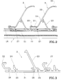
- the support elements 2 also form one or more housings intended to receive retaining members 27 produced in the form of rods, as can be seen more precisely in Figure 1. These rods extend through the housings 25 or 26 and penetrate with their respective ends 271 inside the lateral grooves 17 and 18 formed by the receiving profile 1 as can be seen on the Figure 1. Thus, the support elements 2 are integral with the stiffening profile 1 while able to slide inside the rail 14. It can be seen more precisely in FIG. 3 that each support element 2 is provided with several housings 25 and 26 to receive a rod 27.
- housings 25 in which the rod 27 must be engaged by one end and the housings 26 in which the rod can be inserted over the length of the housing without being introduced by a tip.
- An engaged rod in a housing 25 does not allow to engage the support member 2 in the rail 14 being given that the ends 271 of the rod prevent insertion inside the grooves 17 and 18. In this case, it is necessary to engage the support element in the rail 14 by one of the ends of the stiffening profile 1. It is quite different with the housings 26 which are open along their length, which allows subsequent introduction of the rod. Indeed, it is then possible to engage a support element inside the rail 14 and then accommodate a rod inside one of the two housings or the two housings 26 by introducing the bias rod and engaging its ends in grooves 17 and 18 to finally come the lodge inside one of the housings 26 by a translational movement in the direction longitudinal of the stiffening profile.
- the stiffener profile 1 does not require further machining and can therefore be used as is. Just cut it to the desired length.
- the various elements of support 2 can be positioned anywhere along the length of the profile receiver 1, which gives great flexibility of use.
Landscapes
- Engineering & Computer Science (AREA)
- Combustion & Propulsion (AREA)
- Mechanical Engineering (AREA)
- General Engineering & Computer Science (AREA)
- Chemical & Material Sciences (AREA)
- Blinds (AREA)
- Mutual Connection Of Rods And Tubes (AREA)
- Agricultural Chemicals And Associated Chemicals (AREA)
- Turbine Rotor Nozzle Sealing (AREA)
- Pharmaceuticals Containing Other Organic And Inorganic Compounds (AREA)
- Polarising Elements (AREA)
- Finishing Walls (AREA)
- Specific Sealing Or Ventilating Devices For Doors And Windows (AREA)
Abstract
Description
- la figure 1 est une vue en section transversale verticale à travers un système de fixation selon l'invention,
- la figure 2 est une vue en section transversale verticale du système de fixation de la figure 1 selon un plan de coupe perpendiculaire à celui de la figure 1,
- la figure 3 est une vue agrandie en coupe transversale verticale à travers un élément de support selon l'invention.
Claims (8)
- Système de fixation de lames (3) comprenant :l'élément raidisseur (1) formant un rail longitudinal (14) dans lequel les éléments de support (2) sont engagés, les éléments de support étant pourvus de moyens de retenue engagés dans le rail de manière à maintenir les éléments de support dans le rail de manière coulissante, caractérisé en ce que les éléments de support (2) sont pourvus de moyens de réception adaptés à recevoir les organes de retenue (27).au moins un élément raidisseur (1) disposé transversalement aux lames (3), etplusieurs éléments de support (2) solidaires de l'élément raidisseur (1) et comportant des moyens de fixation (22,23,24) pour les lames (3),
- Système de fixation selon la revendication 1, dans lequel le rail longitudinal (14) forme deux gorges latérales longitudinales (17, 18) ouvertes l'une vers l'autre.
- Système de fixation de lames selon la revendication 2, dans lequel les organes de retenue consistent en des tiges (27) dont les extrémités (271) sont respectivement engagées dans les gorges latérales (17,18) formées par ledit rail.
- Système de fixation de lames selon la revendication 3, dans lequel les moyens de réception comprennent plusieurs logements (25,26) aptes à recevoir chacun une tige (27).
- Système de fixation de lames selon la revendication 4, dans lequel au moins un logement (26) est conçu de manière à permettre la réception d'une tige par introduction latérale sur la longueur du logement, permettent ainsi la mise en place de la tige alors que l'élément de support est déjà engagé dans le rail longitudinal de l'élément raidisseur.
- Système de fixation de lames selon la revendication 4, dans lequel au moins un logement (25) est conçu de manière à permettre la réception d'une tige par introduction coulissante depuis une extrémité ouverte du logement, de sorte que l'élément de support ne peut être engagé dans le rail longitudinal de l'élément raidisseur que par une extrémité de celui-ci.
- Grille de ventilation pour obturer une baie dans un mur comprenant un système de fixation de lame selon l'une quelconque des revendications précédentes.
- Parement de mur comprenant un système de fixation de lame selon l'une quelconque des revendications 1 à 6.
Applications Claiming Priority (2)
| Application Number | Priority Date | Filing Date | Title |
|---|---|---|---|
| FR9915459A FR2802278B1 (fr) | 1999-12-08 | 1999-12-08 | Systeme de fixation de lames |
| FR9915459 | 1999-12-08 |
Publications (2)
| Publication Number | Publication Date |
|---|---|
| EP1111313A1 true EP1111313A1 (fr) | 2001-06-27 |
| EP1111313B1 EP1111313B1 (fr) | 2005-03-09 |
Family
ID=9553008
Family Applications (1)
| Application Number | Title | Priority Date | Filing Date |
|---|---|---|---|
| EP00403435A Expired - Lifetime EP1111313B1 (fr) | 1999-12-08 | 2000-12-07 | Systèmes de fixation de lames |
Country Status (6)
| Country | Link |
|---|---|
| EP (1) | EP1111313B1 (fr) |
| AT (1) | ATE290675T1 (fr) |
| DE (1) | DE60018536T2 (fr) |
| ES (1) | ES2238980T3 (fr) |
| FR (1) | FR2802278B1 (fr) |
| PT (1) | PT1111313E (fr) |
Cited By (2)
| Publication number | Priority date | Publication date | Assignee | Title |
|---|---|---|---|---|
| FR2872889A1 (fr) * | 2004-07-12 | 2006-01-13 | Autogyre Sa | Grille de ventilation destinee a etre installee dans une baie |
| FR2915030A1 (fr) * | 2007-11-08 | 2008-10-17 | Areva T & D Sa | Poste de transformation electrique a grille d'aeration modulable. |
Citations (3)
| Publication number | Priority date | Publication date | Assignee | Title |
|---|---|---|---|---|
| US3968738A (en) * | 1974-04-29 | 1976-07-13 | Champion International Corporation | Plastic louver frame assembly |
| GB2300473A (en) * | 1995-05-03 | 1996-11-06 | Lbj Profiles Limited | Louvre assembly |
| EP0770832A1 (fr) * | 1995-10-26 | 1997-05-02 | Autogyre La Société Anonyme dite : | Grille modulable |
-
1999
- 1999-12-08 FR FR9915459A patent/FR2802278B1/fr not_active Expired - Fee Related
-
2000
- 2000-12-07 PT PT00403435T patent/PT1111313E/pt unknown
- 2000-12-07 EP EP00403435A patent/EP1111313B1/fr not_active Expired - Lifetime
- 2000-12-07 ES ES00403435T patent/ES2238980T3/es not_active Expired - Lifetime
- 2000-12-07 DE DE60018536T patent/DE60018536T2/de not_active Expired - Fee Related
- 2000-12-07 AT AT00403435T patent/ATE290675T1/de not_active IP Right Cessation
Patent Citations (3)
| Publication number | Priority date | Publication date | Assignee | Title |
|---|---|---|---|---|
| US3968738A (en) * | 1974-04-29 | 1976-07-13 | Champion International Corporation | Plastic louver frame assembly |
| GB2300473A (en) * | 1995-05-03 | 1996-11-06 | Lbj Profiles Limited | Louvre assembly |
| EP0770832A1 (fr) * | 1995-10-26 | 1997-05-02 | Autogyre La Société Anonyme dite : | Grille modulable |
Cited By (3)
| Publication number | Priority date | Publication date | Assignee | Title |
|---|---|---|---|---|
| FR2872889A1 (fr) * | 2004-07-12 | 2006-01-13 | Autogyre Sa | Grille de ventilation destinee a etre installee dans une baie |
| EP1617155A1 (fr) * | 2004-07-12 | 2006-01-18 | Autogyre | Grille de ventilation |
| FR2915030A1 (fr) * | 2007-11-08 | 2008-10-17 | Areva T & D Sa | Poste de transformation electrique a grille d'aeration modulable. |
Also Published As
| Publication number | Publication date |
|---|---|
| DE60018536D1 (de) | 2005-04-14 |
| ES2238980T3 (es) | 2005-09-16 |
| FR2802278A1 (fr) | 2001-06-15 |
| ATE290675T1 (de) | 2005-03-15 |
| PT1111313E (pt) | 2005-07-29 |
| DE60018536T2 (de) | 2006-04-13 |
| FR2802278B1 (fr) | 2002-07-19 |
| EP1111313B1 (fr) | 2005-03-09 |
Similar Documents
| Publication | Publication Date | Title |
|---|---|---|
| EP1127394B1 (fr) | Dispositif de fixation d'un fil sur un element porteur muni d'au moins une ouverture et ensemble porteur pour chemin de cables comportant au moins un tel dispositif | |
| EP2115837B1 (fr) | Dispositif de fixation pour chemin de cables en fils | |
| FR2823804A1 (fr) | Ensemble de deux pieces de carrosserie a reunir bord a bord et piece de carosserie appartenant a un tel ensemble | |
| FR2751723A1 (fr) | Eclisse d'assemblage pour troncons de chemins de cables et troncons de chemins de cables obtenus | |
| EP3492675B1 (fr) | Dispositif de fixation de lamelles à panneau grillagé rigide, kit de fixation de lamelles à panneau grillagé rigide et clôture occultante équipée d'un tel kit | |
| EP1149447B1 (fr) | Support d'appareillage, notamment pour appareillage electrique, et boitier comportant un tel support d'appareillage | |
| FR2579262A1 (fr) | Dispositif d'antidecrochage pour porte coulissante | |
| EP1111313B1 (fr) | Systèmes de fixation de lames | |
| FR2982313A1 (fr) | Coffre pour volet roulant, avec organes lateraux de guidage formant tulipes | |
| FR2967734A1 (fr) | Element de fixation | |
| FR2666478A1 (fr) | Boite de montage a entraxe variable, pour appareil electrique. | |
| FR3029022A1 (fr) | Support reversible pour chemin de cables | |
| WO2014049236A1 (fr) | Dispositif de montage d'une goulotte de cablage sur une piece de carrosserie automobile | |
| FR2679939A1 (fr) | Panneau monobloc pour cloison amovible a joints creux ou plats, cloison correspondante et son procede de pose. | |
| FR2710091A1 (fr) | Dispositif de mise en place et de positionnement d'armature dans des coffrages pour béton armé. | |
| EP1617155B1 (fr) | Grille de ventilation | |
| EP1558825A1 (fr) | Faux-plafond mixte a toile tendue | |
| EP1211773B1 (fr) | Support pour appareillage, en particulier pour appareillage électrique, à rapporter sur le socle d'une goulotte | |
| EP1400634B1 (fr) | Dispositif de liaison d'une grille sur un caniveau et outil de demontage correspondant | |
| FR2728401A1 (fr) | Barrette de maintien pour retenir des cables dans une goulotte | |
| FR2880909A1 (fr) | Joue pour coffre de volet et coffre comprenant au moins deux joues | |
| EP3059376A1 (fr) | Procédé d'assemblage d'une installation de fermeture ou de protection solaire, système de support et installation | |
| EP1385244B1 (fr) | Boîtier pour appareillage électrique à rapporter le long d'une goulotte | |
| EP1170844A1 (fr) | Dispositif pour la fixation semi-encastrée d'au moins un appareillage dans un conduit de câblage de profondeur inférieure à celle de l'appareillage | |
| FR2715993A1 (fr) | Coffret de raccordement montable dans un corps creux tel qu'un candélabre. |
Legal Events
| Date | Code | Title | Description |
|---|---|---|---|
| PUAI | Public reference made under article 153(3) epc to a published international application that has entered the european phase |
Free format text: ORIGINAL CODE: 0009012 |
|
| AK | Designated contracting states |
Kind code of ref document: A1 Designated state(s): AT BE CH CY DE DK ES FI FR GB GR IE IT LI LU MC NL PT SE TR |
|
| AX | Request for extension of the european patent |
Free format text: AL;LT;LV;MK;RO;SI |
|
| AKX | Designation fees paid |
Free format text: AT BE CH CY DE DK ES FI FR GB GR IE IT LI LU MC NL PT SE TR |
|
| 17P | Request for examination filed |
Effective date: 20011228 |
|
| GRAP | Despatch of communication of intention to grant a patent |
Free format text: ORIGINAL CODE: EPIDOSNIGR1 |
|
| GRAS | Grant fee paid |
Free format text: ORIGINAL CODE: EPIDOSNIGR3 |
|
| GRAA | (expected) grant |
Free format text: ORIGINAL CODE: 0009210 |
|
| AK | Designated contracting states |
Kind code of ref document: B1 Designated state(s): AT BE CH CY DE DK ES FI FR GB GR IE IT LI LU MC NL PT SE TR |
|
| PG25 | Lapsed in a contracting state [announced via postgrant information from national office to epo] |
Ref country code: FI Free format text: LAPSE BECAUSE OF FAILURE TO SUBMIT A TRANSLATION OF THE DESCRIPTION OR TO PAY THE FEE WITHIN THE PRESCRIBED TIME-LIMIT Effective date: 20050309 |
|
| REG | Reference to a national code |
Ref country code: GB Ref legal event code: FG4D Free format text: NOT ENGLISH |
|
| REG | Reference to a national code |
Ref country code: CH Ref legal event code: EP |
|
| REG | Reference to a national code |
Ref country code: IE Ref legal event code: FG4D Free format text: FRENCH |
|
| REF | Corresponds to: |
Ref document number: 60018536 Country of ref document: DE Date of ref document: 20050414 Kind code of ref document: P |
|
| PG25 | Lapsed in a contracting state [announced via postgrant information from national office to epo] |
Ref country code: GR Free format text: LAPSE BECAUSE OF FAILURE TO SUBMIT A TRANSLATION OF THE DESCRIPTION OR TO PAY THE FEE WITHIN THE PRESCRIBED TIME-LIMIT Effective date: 20050609 Ref country code: DK Free format text: LAPSE BECAUSE OF FAILURE TO SUBMIT A TRANSLATION OF THE DESCRIPTION OR TO PAY THE FEE WITHIN THE PRESCRIBED TIME-LIMIT Effective date: 20050609 |
|
| REG | Reference to a national code |
Ref country code: PT Ref legal event code: SC4A Effective date: 20050603 |
|
| REG | Reference to a national code |
Ref country code: CH Ref legal event code: NV Representative=s name: BOVARD AG PATENTANWAELTE |
|
| GBT | Gb: translation of ep patent filed (gb section 77(6)(a)/1977) |
Effective date: 20050824 |
|
| REG | Reference to a national code |
Ref country code: ES Ref legal event code: FG2A Ref document number: 2238980 Country of ref document: ES Kind code of ref document: T3 |
|
| PG25 | Lapsed in a contracting state [announced via postgrant information from national office to epo] |
Ref country code: IT Free format text: LAPSE BECAUSE OF NON-PAYMENT OF DUE FEES Effective date: 20051207 Ref country code: IE Free format text: LAPSE BECAUSE OF NON-PAYMENT OF DUE FEES Effective date: 20051207 Ref country code: AT Free format text: LAPSE BECAUSE OF NON-PAYMENT OF DUE FEES Effective date: 20051207 Ref country code: CY Free format text: LAPSE BECAUSE OF FAILURE TO SUBMIT A TRANSLATION OF THE DESCRIPTION OR TO PAY THE FEE WITHIN THE PRESCRIBED TIME-LIMIT Effective date: 20051207 |
|
| PG25 | Lapsed in a contracting state [announced via postgrant information from national office to epo] |
Ref country code: ES Free format text: LAPSE BECAUSE OF NON-PAYMENT OF DUE FEES Effective date: 20051209 |
|
| PG25 | Lapsed in a contracting state [announced via postgrant information from national office to epo] |
Ref country code: MC Free format text: LAPSE BECAUSE OF NON-PAYMENT OF DUE FEES Effective date: 20051231 Ref country code: LI Free format text: LAPSE BECAUSE OF NON-PAYMENT OF DUE FEES Effective date: 20051231 Ref country code: LU Free format text: LAPSE BECAUSE OF NON-PAYMENT OF DUE FEES Effective date: 20051231 Ref country code: BE Free format text: LAPSE BECAUSE OF NON-PAYMENT OF DUE FEES Effective date: 20051231 Ref country code: CH Free format text: LAPSE BECAUSE OF NON-PAYMENT OF DUE FEES Effective date: 20051231 |
|
| PLBE | No opposition filed within time limit |
Free format text: ORIGINAL CODE: 0009261 |
|
| STAA | Information on the status of an ep patent application or granted ep patent |
Free format text: STATUS: NO OPPOSITION FILED WITHIN TIME LIMIT |
|
| 26N | No opposition filed |
Effective date: 20051212 |
|
| PG25 | Lapsed in a contracting state [announced via postgrant information from national office to epo] |
Ref country code: NL Free format text: LAPSE BECAUSE OF NON-PAYMENT OF DUE FEES Effective date: 20060701 Ref country code: DE Free format text: LAPSE BECAUSE OF NON-PAYMENT OF DUE FEES Effective date: 20060701 |
|
| REG | Reference to a national code |
Ref country code: CH Ref legal event code: PL |
|
| GBPC | Gb: european patent ceased through non-payment of renewal fee |
Effective date: 20051207 |
|
| PG25 | Lapsed in a contracting state [announced via postgrant information from national office to epo] |
Ref country code: FR Free format text: LAPSE BECAUSE OF NON-PAYMENT OF DUE FEES Effective date: 20060831 |
|
| NLV4 | Nl: lapsed or anulled due to non-payment of the annual fee |
Effective date: 20060701 |
|
| PG25 | Lapsed in a contracting state [announced via postgrant information from national office to epo] |
Ref country code: PT Free format text: LAPSE BECAUSE OF NON-PAYMENT OF DUE FEES Effective date: 20060907 |
|
| REG | Reference to a national code |
Ref country code: IE Ref legal event code: MM4A |
|
| REG | Reference to a national code |
Ref country code: PT Ref legal event code: MM4A Effective date: 20060907 |
|
| REG | Reference to a national code |
Ref country code: FR Ref legal event code: ST Effective date: 20060831 |
|
| REG | Reference to a national code |
Ref country code: ES Ref legal event code: FD2A Effective date: 20051209 |
|
| BERE | Be: lapsed |
Owner name: *AUTOGYRE Effective date: 20051231 |
|
| PG25 | Lapsed in a contracting state [announced via postgrant information from national office to epo] |
Ref country code: SE Free format text: LAPSE BECAUSE OF FAILURE TO SUBMIT A TRANSLATION OF THE DESCRIPTION OR TO PAY THE FEE WITHIN THE PRESCRIBED TIME-LIMIT Effective date: 20050609 |
|
| PG25 | Lapsed in a contracting state [announced via postgrant information from national office to epo] |
Ref country code: PT Free format text: LAPSE BECAUSE OF NON-PAYMENT OF DUE FEES Effective date: 20051207 |
|
| PG25 | Lapsed in a contracting state [announced via postgrant information from national office to epo] |
Ref country code: TR Free format text: LAPSE BECAUSE OF FAILURE TO SUBMIT A TRANSLATION OF THE DESCRIPTION OR TO PAY THE FEE WITHIN THE PRESCRIBED TIME-LIMIT Effective date: 20050309 |