EP1111195A1 - Profilierte, als Anstreifschicht verwendete Oberfläche in Strömungsmaschinen - Google Patents
Profilierte, als Anstreifschicht verwendete Oberfläche in Strömungsmaschinen Download PDFInfo
- Publication number
- EP1111195A1 EP1111195A1 EP00811101A EP00811101A EP1111195A1 EP 1111195 A1 EP1111195 A1 EP 1111195A1 EP 00811101 A EP00811101 A EP 00811101A EP 00811101 A EP00811101 A EP 00811101A EP 1111195 A1 EP1111195 A1 EP 1111195A1
- Authority
- EP
- European Patent Office
- Prior art keywords
- ribs
- profiled
- movement
- rib
- blade tip
- Prior art date
- Legal status (The legal status is an assumption and is not a legal conclusion. Google has not performed a legal analysis and makes no representation as to the accuracy of the status listed.)
- Granted
Links
- 238000009304 pastoral farming Methods 0.000 title 1
- 239000000463 material Substances 0.000 claims abstract description 15
- 230000001680 brushing effect Effects 0.000 claims description 11
- 238000007789 sealing Methods 0.000 claims description 8
- 238000005299 abrasion Methods 0.000 claims description 6
- 239000002184 metal Substances 0.000 claims description 5
- 239000000758 substrate Substances 0.000 claims description 5
- 238000007751 thermal spraying Methods 0.000 claims description 4
- 238000003466 welding Methods 0.000 claims description 4
- 229910010293 ceramic material Inorganic materials 0.000 claims description 3
- 230000001427 coherent effect Effects 0.000 claims description 3
- 230000008021 deposition Effects 0.000 claims description 2
- 238000009792 diffusion process Methods 0.000 claims description 2
- 238000005476 soldering Methods 0.000 claims description 2
- 239000012530 fluid Substances 0.000 claims 1
- 238000002679 ablation Methods 0.000 abstract 1
- ZINJLDJMHCUBIP-UHFFFAOYSA-N ethametsulfuron-methyl Chemical compound CCOC1=NC(NC)=NC(NC(=O)NS(=O)(=O)C=2C(=CC=CC=2)C(=O)OC)=N1 ZINJLDJMHCUBIP-UHFFFAOYSA-N 0.000 description 3
- 239000002245 particle Substances 0.000 description 3
- 239000000919 ceramic Substances 0.000 description 2
- 230000000737 periodic effect Effects 0.000 description 2
- 241000251468 Actinopterygii Species 0.000 description 1
- 230000001419 dependent effect Effects 0.000 description 1
- 229910003460 diamond Inorganic materials 0.000 description 1
- 239000010432 diamond Substances 0.000 description 1
- 239000010419 fine particle Substances 0.000 description 1
- 238000010285 flame spraying Methods 0.000 description 1
- 238000003754 machining Methods 0.000 description 1
- 238000012986 modification Methods 0.000 description 1
- 230000004048 modification Effects 0.000 description 1
- 238000007750 plasma spraying Methods 0.000 description 1
- 229920000642 polymer Polymers 0.000 description 1
- 239000000843 powder Substances 0.000 description 1
- 238000005201 scrubbing Methods 0.000 description 1
- 238000007493 shaping process Methods 0.000 description 1
- 239000004563 wettable powder Substances 0.000 description 1
Images

Classifications
-
- F—MECHANICAL ENGINEERING; LIGHTING; HEATING; WEAPONS; BLASTING
- F01—MACHINES OR ENGINES IN GENERAL; ENGINE PLANTS IN GENERAL; STEAM ENGINES
- F01D—NON-POSITIVE DISPLACEMENT MACHINES OR ENGINES, e.g. STEAM TURBINES
- F01D11/00—Preventing or minimising internal leakage of working-fluid, e.g. between stages
- F01D11/08—Preventing or minimising internal leakage of working-fluid, e.g. between stages for sealing space between rotor blade tips and stator
- F01D11/12—Preventing or minimising internal leakage of working-fluid, e.g. between stages for sealing space between rotor blade tips and stator using a rubstrip, e.g. erodible. deformable or resiliently-biased part
- F01D11/122—Preventing or minimising internal leakage of working-fluid, e.g. between stages for sealing space between rotor blade tips and stator using a rubstrip, e.g. erodible. deformable or resiliently-biased part with erodable or abradable material
-
- F—MECHANICAL ENGINEERING; LIGHTING; HEATING; WEAPONS; BLASTING
- F05—INDEXING SCHEMES RELATING TO ENGINES OR PUMPS IN VARIOUS SUBCLASSES OF CLASSES F01-F04
- F05D—INDEXING SCHEME FOR ASPECTS RELATING TO NON-POSITIVE-DISPLACEMENT MACHINES OR ENGINES, GAS-TURBINES OR JET-PROPULSION PLANTS
- F05D2230/00—Manufacture
- F05D2230/90—Coating; Surface treatment
-
- F—MECHANICAL ENGINEERING; LIGHTING; HEATING; WEAPONS; BLASTING
- F05—INDEXING SCHEMES RELATING TO ENGINES OR PUMPS IN VARIOUS SUBCLASSES OF CLASSES F01-F04
- F05D—INDEXING SCHEME FOR ASPECTS RELATING TO NON-POSITIVE-DISPLACEMENT MACHINES OR ENGINES, GAS-TURBINES OR JET-PROPULSION PLANTS
- F05D2250/00—Geometry
- F05D2250/10—Two-dimensional
- F05D2250/18—Two-dimensional patterned
- F05D2250/181—Two-dimensional patterned ridged
-
- F—MECHANICAL ENGINEERING; LIGHTING; HEATING; WEAPONS; BLASTING
- F05—INDEXING SCHEMES RELATING TO ENGINES OR PUMPS IN VARIOUS SUBCLASSES OF CLASSES F01-F04
- F05D—INDEXING SCHEME FOR ASPECTS RELATING TO NON-POSITIVE-DISPLACEMENT MACHINES OR ENGINES, GAS-TURBINES OR JET-PROPULSION PLANTS
- F05D2250/00—Geometry
- F05D2250/20—Three-dimensional
- F05D2250/28—Three-dimensional patterned
- F05D2250/282—Three-dimensional patterned cubic pattern
-
- F—MECHANICAL ENGINEERING; LIGHTING; HEATING; WEAPONS; BLASTING
- F05—INDEXING SCHEMES RELATING TO ENGINES OR PUMPS IN VARIOUS SUBCLASSES OF CLASSES F01-F04
- F05D—INDEXING SCHEME FOR ASPECTS RELATING TO NON-POSITIVE-DISPLACEMENT MACHINES OR ENGINES, GAS-TURBINES OR JET-PROPULSION PLANTS
- F05D2250/00—Geometry
- F05D2250/20—Three-dimensional
- F05D2250/28—Three-dimensional patterned
- F05D2250/283—Three-dimensional patterned honeycomb
-
- F—MECHANICAL ENGINEERING; LIGHTING; HEATING; WEAPONS; BLASTING
- F05—INDEXING SCHEMES RELATING TO ENGINES OR PUMPS IN VARIOUS SUBCLASSES OF CLASSES F01-F04
- F05D—INDEXING SCHEME FOR ASPECTS RELATING TO NON-POSITIVE-DISPLACEMENT MACHINES OR ENGINES, GAS-TURBINES OR JET-PROPULSION PLANTS
- F05D2250/00—Geometry
- F05D2250/60—Structure; Surface texture
-
- Y—GENERAL TAGGING OF NEW TECHNOLOGICAL DEVELOPMENTS; GENERAL TAGGING OF CROSS-SECTIONAL TECHNOLOGIES SPANNING OVER SEVERAL SECTIONS OF THE IPC; TECHNICAL SUBJECTS COVERED BY FORMER USPC CROSS-REFERENCE ART COLLECTIONS [XRACs] AND DIGESTS
- Y02—TECHNOLOGIES OR APPLICATIONS FOR MITIGATION OR ADAPTATION AGAINST CLIMATE CHANGE
- Y02T—CLIMATE CHANGE MITIGATION TECHNOLOGIES RELATED TO TRANSPORTATION
- Y02T50/00—Aeronautics or air transport
- Y02T50/60—Efficient propulsion technologies, e.g. for aircraft
-
- Y—GENERAL TAGGING OF NEW TECHNOLOGICAL DEVELOPMENTS; GENERAL TAGGING OF CROSS-SECTIONAL TECHNOLOGIES SPANNING OVER SEVERAL SECTIONS OF THE IPC; TECHNICAL SUBJECTS COVERED BY FORMER USPC CROSS-REFERENCE ART COLLECTIONS [XRACs] AND DIGESTS
- Y10—TECHNICAL SUBJECTS COVERED BY FORMER USPC
- Y10T—TECHNICAL SUBJECTS COVERED BY FORMER US CLASSIFICATION
- Y10T29/00—Metal working
- Y10T29/49—Method of mechanical manufacture
- Y10T29/49316—Impeller making
- Y10T29/4932—Turbomachine making
-
- Y—GENERAL TAGGING OF NEW TECHNOLOGICAL DEVELOPMENTS; GENERAL TAGGING OF CROSS-SECTIONAL TECHNOLOGIES SPANNING OVER SEVERAL SECTIONS OF THE IPC; TECHNICAL SUBJECTS COVERED BY FORMER USPC CROSS-REFERENCE ART COLLECTIONS [XRACs] AND DIGESTS
- Y10—TECHNICAL SUBJECTS COVERED BY FORMER USPC
- Y10T—TECHNICAL SUBJECTS COVERED BY FORMER US CLASSIFICATION
- Y10T428/00—Stock material or miscellaneous articles
- Y10T428/24—Structurally defined web or sheet [e.g., overall dimension, etc.]
- Y10T428/24149—Honeycomb-like
Definitions
- the invention relates to a profiled, used as a rubbing layer Surface in turbomachines according to the preamble of claim 1 and a turbomachine with such a surface.
- the profiled, The surface used as the abrasive layer is briefly below Abrasion layer called.
- the Blade tips are usually armored, for example by laser remelting with the simultaneous addition of hard particles so that they Streaking will not be damaged. Released abrasion particles must be without substantial resistance can escape from the sealing gap. From the EP-A-0 935 009 discloses an abradable layer with a profiled surface. For these, it was expected that abrasion particles could be easily removed from the Sealing gap can escape and that also on armor of the Blade tips can be dispensed with. However, tests then showed that on the unarmored blade tips when brushing material in one Way was removed, leading to a corrugated edge of the blade tips led. Such material removal at the blade tips is not tolerable.
- the object of the invention is to provide an abradable layer which is suitable for armored blade tips are suitable. This task is carried out by the im Claim 1 defined stripping layer solved.
- the profiled surface is used as a rubbing layer in turbomachinery used. In this machine, blade tips move in one predetermined direction over the profiled abrasion layer. You generate a partial surface formed by material removal, a rubbing surface.
- the Profiling of the surface is formed by ribs, the chamber-like Surround depressions.
- the ribs are each a rib direction assignable.
- the contact surface forms one of strip-shaped elements built pattern, the elements of which are oriented in the directions of the ribs Connection lines lie between corner points of a reference grid. Largely at every point of the brushing surface - d. H. to more than 80 - 95% of the Brushing surface - the direction of the ribs differs from that Direction of movement of the blade tips.
- the contact surface deviates the direction of movement from the direction of the ribs more than 30 °, preferably more than 45 °.
- the stripe-shaped elements The contact surface can be curved as well as discrete and / or partial contiguous stripes.
- the profiling Abrasive layer taking into account the direction of movement of the If blade tips are carried out, there is less material removal on the unarmored blade tips and also a material removal, which is evenly distributed over the entire edge of a tip. To the It is also possible to reduce material removal at the blade tips even further be provided to armor the blade tips.
- the dependent claims 2 to 7 relate to advantageous embodiments the abradable layer according to the invention.
- Subject matter of claims 8 to 10 is a turbomachine with such an abradable layer.
- the abradable layer 1 shown as a cross section in FIG. 1 has a profiled one Surface over which a blade tip 2 in a predetermined direction v moves. Ribs 15 form the profile of the Surface; they surround chamber-like depressions 11. An original one Surface 10 ′′ of the abradable layer 1 is indicated by dash-dotted lines Brushing surface 10 in a plane 10 ′ is through by blade tip 2 Material removal has been formed. A narrow gap between level 20 and the abradable surface 10 is one created by the material removal Sealing gap.
- the abradable surface 10 forms a pattern that one is made of can imagine strip-shaped elements 5 constructed.
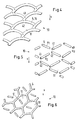
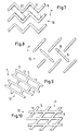
- the following Figures 3 to 12 show various patterns of Brushing surface 10, as they result from material removal from the invention Scrubbing layers 1 result.
- the strip-shaped elements 5 of the Brush surface 10 can be curved; they can also be discrete and / or partially coherent strips are present.
- the abradable layer 1 is applied by thermal spraying onto a metallic Substrate 3 applied, using a material that is used for the Use at high temperatures, for example, contains ceramic material and already for use with non-profiled abrasion layers may be known (see e.g. US-A-5 434 210).
- the substrate 3 has one profiled surface with webs 35. This profiling can be done in different forms: as a molded profile of a Cast body; than by EDM or by mechanical Profiling on a originally produced machining process flat metal body; as a profiling from woven or individual Metal wires by soldering or by means of laser or diffusion welding are applied to a metal body; or as a profiling in the form of ribs, which are micro-cast by laser deposition welding are applied.
- the widths of the strip-shaped elements 5 are larger than around 1 mm. With that at No material damage from the abradable layer 1, these widths must be of the same order of magnitude as that Cross-sectional width of the blade tip (width in the direction of travel v): it should not exceed one to three times this cross-sectional width.
- the webs 35 have cross sections which are against a fuselage 30 of the Narrow substrate 3. You can also form gaps to the fuselage 30, like this is known from the above-mentioned EP-A-0 935 009. Based on these Shaping is the material forming the abradable layer 1 in depressions 31 anchored between the webs 35.
- a rib direction can be assigned to each of the ribs 15.
- the direction of the ribs must largely change at every point of the contact surface 10 differ from the direction of movement v of the blade tip 2. It is "largely” means that at most 5 - 15% or 20% of the Contact surface 10 has the same orientation of the blade movement and the Ribs present. To what extent these alignments can be the same must be determined empirically.
- the rubbing surface 10 must have the direction of movement v of the direction of the ribs deviate by more than 30 °, preferably more than 45 °. If these conditions are met, an unarmored Blade tip 2 can be used.
- FIG. 3 shows a first pattern of the abradable surface 10 of an abradable layer 1 according to the invention.
- the pattern is constructed from the strip-shaped elements 5. These elements 5 lie in the directions of the ribs 15 on connecting lines 45 between corner points 41, 42 of a reference grid 40.
- Each corner point 41 or 42 of the reference grid 40 can be assigned three axes x 1 , x 2 , y. Angles ⁇ 12 , ⁇ 2 and ⁇ 1 are spanned between these axes.
- Ribs 15, which are denoted by a 1 , a 2 , b, lie on the axes x 1 , x 2 and y, respectively. Ribs a 1 and a 2 are longer than rib b by a factor greater than 2.
- the angles ⁇ 1 , ⁇ 2 , ⁇ 12 are each greater than 100 ° and smaller than 150 ° (total 360 °).
- the pattern shown has a generalized honeycomb structure: the ribs 15 of the chamber-like depressions 11 can be assigned connecting lines 45 between six corner points of the reference grid 40, namely three corner points 41 and three corner points 42.
- Each axis y is at least approximately parallel to a single y direction.
- the direction of movement v of the blade tip 2 deviates from the y direction a small angle that is a maximum of 30 °.
- the rib is preferably b compared to the ribs a1, a2 much smaller, namely by a factor that is greater than 3.
- the corner points 41 and 42 assigned to the rib b can be so close together that rib b is practically negligible, d. H. does not exist.
- Figures 4 and 5 show modifications of the first pattern (Fig. 3).
- the pattern has a structure resembling a fish scale covering.
- the ribs 15 are curved.
- the pattern is composed of discrete elements 5. There are only ribs a 1 and a2; there are gaps instead of the ribs b.
- FIG. 6 again shows a pattern of the contact surface 10, which is honeycomb-like.
- elements 5 ' are arranged as islands.
- the strip-shaped elements 5 are connected on zigzag lines arranged.
- the angles between the rib directions and the Direction of movement v is preferably 45 ° or somewhat larger.
- the Limits of the chamber-like depressions 11 cannot be clearly defined here specify; for example, they can be drawn as dash-dotted lines Rectangles 11 'can be viewed.
- 8 shows like FIG. 5 again Pattern with discrete elements 5.
- This pattern has a certain Relationship to the zigzag pattern of Fig. 7 by this pattern every other element 5 of the zigzag strip removed and the remaining remaining elements 5 can be extended at both ends.
- FIG. 9 shows a pattern with depressions 11 which are rectangular and offset from one another are arranged.
- a diamond pattern is shown in Fig. 10, in which one Rib direction is perpendicular to the direction of movement v and the other Rib direction with the direction of movement v an angle of around 45 ° includes.
- the brushing surfaces have 10 each have a profile
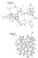
- the reference grid 40 periodically arranged unit cells can be built. It is non-periodic profiling is also possible, the reference grid 40 for example, has a "Penrose structure" according to FIG. 11. 12 shows a corresponding pattern of a contact surface 10 with depressions 11 ' and 11 ", which are pentagonal or diamond-shaped.
- This reference grid 40 comprises uniform pentagons (angle between adjacent sides: 108 °) and Rhombuses (angles: 36 ° and 144 °). While in the periodic grating two or three main directions, there are five in the "Penrose structure" Main directions. The direction of movement v of the blade tips 2 also deviates Advantage of around 18 ° from one of these main directions.
- each corner point 43 or 44 of the reference grid 40 can be assigned three axes x 1 , x2, y. Angles ⁇ 12 , ⁇ 2 and ⁇ 1 are spanned between these axes. Ribs a 1 , a2 lie on the axes x 1 , x 2 . The ribs a 1 and a2 are largely of the same length. The angles ⁇ 1 , ⁇ 2 , ⁇ 12 are each greater than 100 ° and smaller than 150 ° (total 360 °).
- a rib b lies on the axis y.
- the ribs b or b 1 and b2 are largely of the same length as a 1 or a 2 .
- An angle ⁇ 12 between b 1 and b2 is greater than 30 ° and less than 45 °.
- the direction of movement v of the blade tip 2 is essentially parallel to the axis y of one of the bifurcations.
- the abradable layers described above can be used instead of on one Housing wall can also be applied to a movable machine part, namely if the blade is arranged stationary, in particular one Guide vane is, and the sealing gap between the dormant Blade tip and the moving machine part is located, which Machine part is in particular a rotor shaft.
- Abrasive layers can also be attached to the tips of stationary blades on shrouds. The movement of the blade tip mentioned in claim 1 is therefore as To understand relative movement.
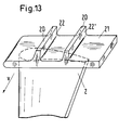
- a turbomachine with an abradable layer 1 according to the invention may also contain blades, the tips 2 of which each form a shroud 21 are formed (shrouded blade): see FIG. 13.
- the cover band 21 has one or more slats 22, 22 ', which are in the Extend direction of movement v of the blade tip 2. If there is one The majority of the lamellae 22, 22 'form a labyrinth seal.
Landscapes
- Engineering & Computer Science (AREA)
- Mechanical Engineering (AREA)
- General Engineering & Computer Science (AREA)
- Turbine Rotor Nozzle Sealing (AREA)
- Coating With Molten Metal (AREA)
- Polishing Bodies And Polishing Tools (AREA)
- Electroplating Methods And Accessories (AREA)
- Sealing Using Fluids, Sealing Without Contact, And Removal Of Oil (AREA)
- Sealing Devices (AREA)
Abstract
Description
- Fig. 1
- einen Querschnitt durch eine Anstreifschicht mit über einer Anstreiffläche laufenden Schaufelspitze,
- Fig. 2
- ein Schrägbild der Anstreifschicht,
- Fig. 3
- ein erstes Muster der Anstreiffläche einer erfindungsgemässen Anstreifschicht,
- Fig. 4, 5
- Abwandlungen des ersten Musters,
- Fig. 6 - 10
- Muster weiterer Anstreifflächen gemäss der Erfindung,
- Fig. 11
- ein Bezugsgitter mit einer "Penrose"-Struktur, die gleichmässige Fünfecke und Rauten umfasst,
- Fig. 12
- ein entsprechendes Muster einer Anstreiffläche und
- Fig. 13
- eine Schaufelspitze mit Deckband.
Claims (10)
- Profilierte, als Anstreifschicht (1) verwendete Oberfläche in Strömungsmaschinen, in der sich Schaufelspitzen (2) in einer vorgegebenen Richtung (v) über die profilierte Anstreifschicht bewegen und dabei eine durch Materialabtrag gebildete Teilfäche - eine Anstreiffläche (10) - erzeugen, wobei die Profilierung der Anstreifschicht durch Rippen (15) gebildet ist, den Rippen jeweils eine Rippenrichtung zuordenbar ist und die Anstreiffläche ein aus streifenförmigen Elementen (5) aufgebautes Muster bildet, dessen Elemente in den Richtungen der Rippen auf Verbindungslinien (45) zwischen Eckpunkten (41, 42; 43, 44) eines Bezugsgitters (40) liegen, dadurch gekennzeichnet, dass
weitgehend an jeder Stelle der Anstreiffläche (10) - d. h. zu
mindestens 80%, vorzugsweise mehr als 95% der Anstreiffläche - die Rippenrichtung sich von der Bewegungsrichtung (v) der Schaufelspitzen (2) unterscheidet, dass für mindestens zwei Drittel der Anstreiffläche die Bewegungsrichtung von der Rippenrichtung um mehr als 30°, vorzugsweise mehr als 45° abweicht und dass die streifenförmigen Elemente (5) der Anstreiffläche gekrümmte sowie diskrete und/oder zusammenhängende oder teilweise zusammenhängende Streifen sein können. - Profilierte Oberfläche nach Anspruch 1, dadurch gekennzeichnet, dass jedem Eckpunkt (41, 42) des Bezugsgitters (40) drei Achsen x1, x2, y zuordenbar sind und zwischen diesen Achsen Winkel α12, α2, bzw. α1 aufgespannt sind, dass Rippen a1, a2, b auf den Achsen x1, x2 bzw. y liegen, wobei a1 und a2 verglichen mit b um einen Faktor 2 oder mehr länger sind und die Winkel α1, α2, α12 jeweils grösser als 100° und kleiner als 150° sind, dass alle Achsen y zumindest angenähert parallel zueinander, d. h. in einer einzigen y-Richtung orientiert sind und dass die Bewegungsrichtung (v) der Schaufelspitze (2) von der y-Richtung um einen kleinen Winkel abweicht, der maximal 30° ist.
- Profilierte Oberfläche nach Anspruch 1 oder 2, dadurch gekennzeichnet, dass den Rippen (15) der kammerartigen Vertiefung (11) Verbindungslinien (45) zwischen jeweils sechs Eckpunkten (41, 42) des Bezugsgitters (40) zuordenbar sind.
- Profilierte Oberfläche nach den Ansprüchen 2 und 3, dadurch gekennzeichnet, dass anstelle der Rippe b eine Lücke besteht; oder dass die Rippen a1, a2 um einen Faktor 3 oder mehr länger als die Rippe b sind; oder dass die Länge der Rippe b praktisch vernachlässigbar ist.
- Profilierte Oberfläche nach Anspruch 1, dadurch gekennzeichnet, dass jedem Eckpunkt (43, 44) des Bezugsgitters (40) drei Achsen x1, X2, y zuordenbar sind und zwischen diesen Achsen Winkel α12, α2, bzw. α1 aufgespannt sind, dass Rippen a1, a2 auf den Achsen x1, x2 liegen, wobei die Rippen a1 und a2 weitgehend gleich lang sind und die Winkel α1, α2, α12 jeweils grösser als 100° und kleiner als 150° sind, dass für einen Teil der Eckpunkte (43) eine Rippe b auf der Achse y liegt und für die weiteren Eckpunkte (44) jeweils eine Gabelung um die Achse y mit zwei Rippen b1, b2 gegeben ist, wobei b bzw. b1 und b2 weitgehend gleich lang wie a1 oder a2 sind, ein Winkel β12 zwischen b1 und b2 grösser als 30° und kleiner als 45° ist und die Bewegungsrichtung der Schaufelspitze im wesentlichen parallel zu der Achse y einer der Gabelungen ist.
- Profilierte Oberfläche nach einem der Ansprüche 1 bis 5, dadurch gekennzeichnet, dass die Breiten der streifenförmigen Elemente (5) grösser als rund 1 mm sind und in der gleichen Grössenordnung wie die Querschnittsbreite der Schaufelspitze, insbesondere kleiner als das Ein- bis Dreifache dieser Breite sind.
- Profilierte Oberfläche nach einem der Ansprüche 1 bis 6, dadurch gekennzeichnet, dass sie durch thermisches Spritzen auf ein metallisches Substrat (3) mit einem Material hergestellt ist, das für bekannte, nichtprofilierte Anstreifschichten geeignet ist und das insbesondere keramisches Material enthält, wobei das Substrat eine profilierte, Stege (35) aufweisende Oberfläche hat und die Profilierung in verschiedenen Formen vorliegen kann: als gegossene Profilierung eines Gusskörpers; als eine Profilierung aus gewobenen oder einzelnen Metalldrähten, die durch Löten oder mittels einem Laser-oder Diffusionsschweissen auf einen Metallkörper aufgebracht sind; oder als eine Profilierung in Form von Rippen, die durch ein Laserauftragschweissen mikrogussartig aufgetragen sind.
- Strömungsmaschine, insbesondere Gasturbine, mit profilierter, als Anstreifschicht (1) verwendeter Oberfläche gemäss einem der Ansprüche 1 bis 7, dadurch gekennzeichnet, dass die Schaufelspitze (2) Teil einer Laufschaufel ist.
- Strömungsmaschine nach Anspruch 8, dadurch gekennzeichnet, dass ein Deckband die Schaufelspitze (2) bildet, das eine oder mehrere Lamellen aufweist, die sich in der Bewegungsrichtung (v) der Schaufelspitze erstrecken und dabei insbesondere als Dichtlippen einer Labyrinthdichtung ausgebildet sind.
- Strömungsmaschine, insbesondere Gasturbine, mit profilierter, als Anstreifschicht (1) verwendeter Oberfläche gemäss einem der Ansprüche 1 bis 7, dadurch gekennzeichnet, dass die Schaufelspitze (2) Teil einer stationären Leitschaufel ist, und ein Dichtspalt sich zwischen der Schaufelspitze und einem bewegten Maschinenteil befindet, wobei die Anstreifschicht auf einem Deckband an der Spitze der stationären Schaufel oder auf der Oberfläche einer Rotorwelle angebracht sein kann und die in Anspruch 1 genannte Bewegung der Schaufelspitze als Relativbewegung zu verstehen ist.
Priority Applications (1)
| Application Number | Priority Date | Filing Date | Title |
|---|---|---|---|
| EP00811101.5A EP1111195B2 (de) | 1999-12-20 | 2000-11-21 | Profilierte, als Anstreifschicht verwendete Oberfläche in Strömungsmaschinen |
Applications Claiming Priority (3)
| Application Number | Priority Date | Filing Date | Title |
|---|---|---|---|
| EP99811170 | 1999-12-20 | ||
| EP99811170 | 1999-12-20 | ||
| EP00811101.5A EP1111195B2 (de) | 1999-12-20 | 2000-11-21 | Profilierte, als Anstreifschicht verwendete Oberfläche in Strömungsmaschinen |
Publications (3)
| Publication Number | Publication Date |
|---|---|
| EP1111195A1 true EP1111195A1 (de) | 2001-06-27 |
| EP1111195B1 EP1111195B1 (de) | 2009-01-07 |
| EP1111195B2 EP1111195B2 (de) | 2013-05-01 |
Family
ID=8243195
Family Applications (1)
| Application Number | Title | Priority Date | Filing Date |
|---|---|---|---|
| EP00811101.5A Expired - Lifetime EP1111195B2 (de) | 1999-12-20 | 2000-11-21 | Profilierte, als Anstreifschicht verwendete Oberfläche in Strömungsmaschinen |
Country Status (7)
| Country | Link |
|---|---|
| US (1) | US6457939B2 (de) |
| EP (1) | EP1111195B2 (de) |
| JP (2) | JP4755336B2 (de) |
| AT (1) | ATE420272T1 (de) |
| CA (1) | CA2326992C (de) |
| DE (1) | DE50015514D1 (de) |
| ES (1) | ES2319253T5 (de) |
Cited By (5)
| Publication number | Priority date | Publication date | Assignee | Title |
|---|---|---|---|---|
| FR2832180A1 (fr) * | 2001-11-14 | 2003-05-16 | Snecma Moteurs | Revetement abradable pour parois de turbines a gaz |
| WO2008103163A3 (en) * | 2007-02-22 | 2009-05-22 | Siemens Energy Inc | Ceramic matrix composite abradable via reduction of surface area |
| EP2141328A1 (de) * | 2008-07-03 | 2010-01-06 | Siemens Aktiengesellschaft | Dichtungssystem zwischen einem Mantelringsegment und einer Laufschaufelspitze und Herstellungsverfahren für ein solches Segment |
| EP2687684A1 (de) | 2012-07-17 | 2014-01-22 | MTU Aero Engines GmbH | Anstreifbelag mit Spiralnuten in einer Strömungsmaschine |
| DE102005050873B4 (de) * | 2005-10-21 | 2020-08-06 | Rolls-Royce Deutschland Ltd & Co Kg | Verfahren zur Herstellung einer segmentierten Beschichtung und nach dem Verfahren hergestelltes Bauteil |
Families Citing this family (77)
| Publication number | Priority date | Publication date | Assignee | Title |
|---|---|---|---|---|
| DE10117127B4 (de) * | 2001-04-06 | 2009-12-31 | Alstom Technology Ltd. | Verbundaufbau zwischen metallischen und nichtmetallischen Materialien |
| DE10117128A1 (de) * | 2001-04-06 | 2002-10-10 | Alstom Switzerland Ltd | Verfahren zur Herstellung von Verbundaufbauten zwischen metallischen und nichtmetallischen Materialien |
| EP1275748A3 (de) | 2001-07-13 | 2004-01-07 | ALSTOM (Switzerland) Ltd | Hochtemperaturbeständiger Schutzüberzug mit eingebetteten lokalen Erhebungen sowie Verfahren zur Herstellung des Schutzüberzuges |
| WO2003010419A1 (de) * | 2001-07-23 | 2003-02-06 | Alstom Technology Ltd | Vorrichtung zur dichtspaltreduzierung zwischen bewegten und stationären komponenten innerhalb einer strömungsmaschine |
| US20050003172A1 (en) * | 2002-12-17 | 2005-01-06 | General Electric Company | 7FAstage 1 abradable coatings and method for making same |
| US6887528B2 (en) * | 2002-12-17 | 2005-05-03 | General Electric Company | High temperature abradable coatings |
| US6890150B2 (en) * | 2003-08-12 | 2005-05-10 | General Electric Company | Center-located cutter teeth on shrouded turbine blades |
| US6905309B2 (en) * | 2003-08-28 | 2005-06-14 | General Electric Company | Methods and apparatus for reducing vibrations induced to compressor airfoils |
| US7026016B2 (en) * | 2004-01-02 | 2006-04-11 | Bauer Eric C | Method of fabricating free standing objects using thermal spraying |
| US7600968B2 (en) * | 2004-11-24 | 2009-10-13 | General Electric Company | Pattern for the surface of a turbine shroud |
| US7614847B2 (en) * | 2004-11-24 | 2009-11-10 | General Electric Company | Pattern for the surface of a turbine shroud |
| US7247002B2 (en) * | 2004-12-02 | 2007-07-24 | Siemens Power Generation, Inc. | Lamellate CMC structure with interlock to metallic support structure |
| US7955708B2 (en) * | 2005-10-07 | 2011-06-07 | Sulzer Metco (Us), Inc. | Optimized high temperature thermal barrier |
| US20080260522A1 (en) * | 2007-04-18 | 2008-10-23 | Ioannis Alvanos | Gas turbine engine with integrated abradable seal and mount plate |
| US9297269B2 (en) * | 2007-05-07 | 2016-03-29 | Siemens Energy, Inc. | Patterned reduction of surface area for abradability |
| US20090097979A1 (en) * | 2007-07-31 | 2009-04-16 | Omer Duane Erdmann | Rotor blade |
| US20100047526A1 (en) * | 2008-08-19 | 2010-02-25 | Merrill Gary B | Subsurface inclusions of spheroids and methodology for strengthening a surface bond in a hybrid ceramic matrix composite structure |
| US20100047512A1 (en) * | 2008-08-19 | 2010-02-25 | Morrison Jay A | Methodology and tooling arrangements for strengthening a surface bond in a hybrid ceramic matrix composite structure |
| US7704596B2 (en) | 2008-09-23 | 2010-04-27 | Siemens Energy, Inc. | Subsurface inclusion of fugitive objects and methodology for strengthening a surface bond in a hybrid ceramic matrix composite structure |
| US8348603B2 (en) * | 2009-04-02 | 2013-01-08 | General Electric Company | Gas turbine inner flowpath coverpiece |
| US8852720B2 (en) * | 2009-07-17 | 2014-10-07 | Rolls-Royce Corporation | Substrate features for mitigating stress |
| EP2319641B1 (de) * | 2009-10-30 | 2017-07-19 | Ansaldo Energia IP UK Limited | Verfahren zur Anwendung mehrerer Materialien mit selektivem Laserschmelzen auf einem dreidimensionalen Artikel |
| IT1396362B1 (it) | 2009-10-30 | 2012-11-19 | Nuovo Pignone Spa | Macchina con righe in rilievo che possono essere abrase e metodo. |
| EP2317076B1 (de) * | 2009-10-30 | 2018-02-14 | Ansaldo Energia IP UK Limited | Verfahren zum Reparieren einer Gasturbinenkomponente |
| EP2317075B1 (de) * | 2009-10-30 | 2013-01-02 | Alstom Technology Ltd | Verfahren zum Reparieren einer Gasturbinenkomponente |
| EP2317079B1 (de) | 2009-10-30 | 2020-05-20 | Ansaldo Energia Switzerland AG | Abriebsbeschichtungssystem |
| US8506243B2 (en) * | 2009-11-19 | 2013-08-13 | United Technologies Corporation | Segmented thermally insulating coating |
| JP5767248B2 (ja) | 2010-01-11 | 2015-08-19 | ロールス−ロイス コーポレイション | 環境障壁コーティングに加わる熱又は機械的応力を軽減するための特徴体 |
| US20110189924A1 (en) * | 2010-01-29 | 2011-08-04 | Erickson Robert E | Method of machining between contoured surfaces with cup shaped tool |
| GB2483060B (en) * | 2010-08-23 | 2013-05-15 | Rolls Royce Plc | A turbomachine casing assembly |
| DE102010062087A1 (de) * | 2010-11-29 | 2012-05-31 | Siemens Aktiengesellschaft | Strömungsmaschine mit Dichtstruktur zwischen drehenden und ortsfesten Teilen sowie Verfahren zur Herstellung dieser Dichtstruktur |
| EP2458157B1 (de) | 2010-11-30 | 2015-10-14 | Techspace Aero S.A. | Abriebdichtung eines Stator-Innenrings |
| DE102010060944B3 (de) * | 2010-12-01 | 2012-04-05 | Bbat Berlin Brandenburg Aerospace Technology Ag | Wärmedämmende Auskleidung für eine Fluggasturbine |
| DE102011077620A1 (de) | 2011-06-16 | 2012-12-20 | Rolls-Royce Deutschland Ltd & Co Kg | Bauelement, Verfahren zur Herstellung eines Bauelementes und Flugzeugtriebwerk mit einem Bauelement |
| US20130017072A1 (en) * | 2011-07-14 | 2013-01-17 | General Electric Company | Pattern-abradable/abrasive coatings for steam turbine stationary component surfaces |
| US8888446B2 (en) * | 2011-10-07 | 2014-11-18 | General Electric Company | Turbomachine rotor having patterned coating |
| DE102011085801A1 (de) | 2011-11-04 | 2013-05-08 | Fraunhofer-Gesellschaft zur Förderung der angewandten Forschung e.V. | Bauelement und Turbomaschine mit einem Bauelement |
| US9022743B2 (en) | 2011-11-30 | 2015-05-05 | United Technologies Corporation | Segmented thermally insulating coating |
| DE102012200883B4 (de) * | 2012-01-23 | 2015-12-03 | MTU Aero Engines AG | Strömungsmaschinen-Dichtungsanordnung |
| JP5308548B2 (ja) * | 2012-02-06 | 2013-10-09 | 三菱重工業株式会社 | シール構造及びこれを備える回転機械 |
| US10040094B2 (en) | 2013-03-15 | 2018-08-07 | Rolls-Royce Corporation | Coating interface |
| FR3007063B1 (fr) * | 2013-06-13 | 2015-07-03 | Composite Ind | Piece de materiau abradable pour la fabrication d'un secteur de joint annulaire abradable pour turbomachine et procede de fabrication d'une telle piece |
| US9289917B2 (en) | 2013-10-01 | 2016-03-22 | General Electric Company | Method for 3-D printing a pattern for the surface of a turbine shroud |
| US9249680B2 (en) | 2014-02-25 | 2016-02-02 | Siemens Energy, Inc. | Turbine abradable layer with asymmetric ridges or grooves |
| EP3111055A2 (de) * | 2014-02-25 | 2017-01-04 | Siemens Aktiengesellschaft | Wärmedämmschicht für turbinenkomponente mit tiefenvariierenden materialeigenschaften |
| US8939707B1 (en) | 2014-02-25 | 2015-01-27 | Siemens Energy, Inc. | Turbine abradable layer with progressive wear zone terraced ridges |
| US9151175B2 (en) | 2014-02-25 | 2015-10-06 | Siemens Aktiengesellschaft | Turbine abradable layer with progressive wear zone multi level ridge arrays |
| US8939716B1 (en) | 2014-02-25 | 2015-01-27 | Siemens Aktiengesellschaft | Turbine abradable layer with nested loop groove pattern |
| US9243511B2 (en) | 2014-02-25 | 2016-01-26 | Siemens Aktiengesellschaft | Turbine abradable layer with zig zag groove pattern |
| WO2016133987A2 (en) | 2015-02-18 | 2016-08-25 | Siemens Aktiengesellschaft | Forming cooling passages in combustion turbine superalloy castings |
| US8939705B1 (en) | 2014-02-25 | 2015-01-27 | Siemens Energy, Inc. | Turbine abradable layer with progressive wear zone multi depth grooves |
| US8939706B1 (en) * | 2014-02-25 | 2015-01-27 | Siemens Energy, Inc. | Turbine abradable layer with progressive wear zone having a frangible or pixelated nib surface |
| EP3143259B1 (de) * | 2014-05-15 | 2020-08-05 | Nuovo Pignone S.r.l. | Verfahren zur herstellung eines bauteils einer strömungsmaschine, bauteil einer strömungsmaschine und strömungsmaschine |
| US10174481B2 (en) | 2014-08-26 | 2019-01-08 | Cnh Industrial America Llc | Shroud wear ring for a work vehicle |
| US10132185B2 (en) | 2014-11-07 | 2018-11-20 | Rolls-Royce Corporation | Additive process for an abradable blade track used in a gas turbine engine |
| US20160201498A1 (en) * | 2014-12-15 | 2016-07-14 | United Technologies Corporation | Seal coating |
| US10273192B2 (en) | 2015-02-17 | 2019-04-30 | Rolls-Royce Corporation | Patterned abradable coating and methods for the manufacture thereof |
| WO2016133583A1 (en) | 2015-02-18 | 2016-08-25 | Siemens Aktiengesellschaft | Turbine shroud with abradable layer having ridges with holes |
| JP6702305B2 (ja) * | 2015-03-24 | 2020-06-03 | 日立金属株式会社 | セラミックハニカム構造体 |
| US9951642B2 (en) * | 2015-05-08 | 2018-04-24 | United Technologies Corporation | Intermittent grooved soft abradable material to reduce blade tip temperature |
| DE102015216208A1 (de) * | 2015-08-25 | 2017-03-02 | Rolls-Royce Deutschland Ltd & Co Kg | Dichtelement für eine Turbomaschine, Turbomaschine mit einem Dichtelement und Verfahren zur Herstellung eines Dichtelementes |
| US20170089213A1 (en) | 2015-09-28 | 2017-03-30 | United Technologies Corporation | Duct with additive manufactured seal |
| ITUB20155442A1 (it) * | 2015-11-11 | 2017-05-11 | Ge Avio Srl | Stadio di un motore a turbina a gas provvisto di una tenuta a labirinto |
| US10731482B2 (en) | 2015-12-04 | 2020-08-04 | Raytheon Technologies Corporation | Enhanced adhesion thermal barrier coating |
| JP2017160861A (ja) * | 2016-03-10 | 2017-09-14 | 株式会社日立製作所 | ターボ機械 |
| JP6896385B2 (ja) * | 2016-08-10 | 2021-06-30 | 三菱重工航空エンジン株式会社 | アブレイダブルコーティングの施工方法 |
| DE102017209658A1 (de) * | 2017-06-08 | 2018-12-13 | MTU Aero Engines AG | Einlaufstruktur für eine Strömungsmaschine, Strömungsmaschine mit einer Einlaufstruktur und Verfahren zum Herstellen einer Einlaufstruktur |
| US10900371B2 (en) | 2017-07-27 | 2021-01-26 | Rolls-Royce North American Technologies, Inc. | Abradable coatings for high-performance systems |
| US10858950B2 (en) | 2017-07-27 | 2020-12-08 | Rolls-Royce North America Technologies, Inc. | Multilayer abradable coatings for high-performance systems |
| FR3073890B1 (fr) * | 2017-11-21 | 2021-01-22 | Safran Aircraft Engines | Abradable de joint a labyrinthe, notamment pour turbine d'aeronef |
| US10995623B2 (en) | 2018-04-23 | 2021-05-04 | Rolls-Royce Corporation | Ceramic matrix composite turbine blade with abrasive tip |
| US11346232B2 (en) | 2018-04-23 | 2022-05-31 | Rolls-Royce Corporation | Turbine blade with abradable tip |
| US10927695B2 (en) | 2018-11-27 | 2021-02-23 | Raytheon Technologies Corporation | Abradable coating for grooved BOAS |
| FR3095025B1 (fr) * | 2019-04-12 | 2021-03-05 | Safran Aircraft Engines | Joint d’étanchéité à labyrinthe comportant un élément abradable à densité variable de cellules |
| US11674396B2 (en) | 2021-07-30 | 2023-06-13 | General Electric Company | Cooling air delivery assembly |
| US11674405B2 (en) | 2021-08-30 | 2023-06-13 | General Electric Company | Abradable insert with lattice structure |
| CN114066917B (zh) * | 2021-11-11 | 2022-08-05 | 深圳市云鼠科技开发有限公司 | 一种清扫方法、装置、电子设备和存储介质 |
Citations (7)
| Publication number | Priority date | Publication date | Assignee | Title |
|---|---|---|---|---|
| US3053694A (en) * | 1961-02-20 | 1962-09-11 | Gen Electric | Abradable material |
| US4594053A (en) * | 1984-04-10 | 1986-06-10 | Mtu Motoren-Und Turbinen-Union Muenchen Gmbh | Housing for a fluid flow or jet engine |
| US4867639A (en) * | 1987-09-22 | 1989-09-19 | Allied-Signal Inc. | Abradable shroud coating |
| US5064727A (en) * | 1990-01-19 | 1991-11-12 | Avco Corporation | Abradable hybrid ceramic wall structures |
| US5434210A (en) | 1990-11-19 | 1995-07-18 | Sulzer Plasma Technik, Inc. | Thermal spray powders for abradable coatings, abradable coatings containing solid lubricants and methods of fabricating abradable coatings |
| EP0935009A1 (de) | 1998-02-05 | 1999-08-11 | Sulzer Innotec Ag | Beschichteter Gusskörper |
| US5951892A (en) * | 1996-12-10 | 1999-09-14 | Chromalloy Gas Turbine Corporation | Method of making an abradable seal by laser cutting |
Family Cites Families (14)
| Publication number | Priority date | Publication date | Assignee | Title |
|---|---|---|---|---|
| US3042365A (en) | 1957-11-08 | 1962-07-03 | Gen Motors Corp | Blade shrouding |
| US3916054A (en) * | 1973-02-23 | 1975-10-28 | Int Harvester Co | Compliant structural members |
| US3867061A (en) * | 1973-12-26 | 1975-02-18 | Curtiss Wright Corp | Shroud structure for turbine rotor blades and the like |
| US4289447A (en) * | 1979-10-12 | 1981-09-15 | General Electric Company | Metal-ceramic turbine shroud and method of making the same |
| DE8013163U1 (de) * | 1980-05-16 | 1988-10-13 | MTU Motoren- und Turbinen-Union München GmbH, 8000 München | Gehäuse für eine thermische Turbomaschine mit einer wärmedämmenden Auskleidung |
| US4346904A (en) * | 1980-11-26 | 1982-08-31 | Watkins Jr Shelton | Honeycomb structure for use in abradable seals |
| JPS5795500A (en) * | 1980-12-04 | 1982-06-14 | Tamasaki Mitsue | Propelling pencil, lead thereof is delivered automatically |
| US4416457A (en) * | 1983-01-24 | 1983-11-22 | Westinghouse Electric Corp. | Grooved honeycomb labyrinth seal for steam turbines |
| FR2552159B1 (fr) * | 1983-09-21 | 1987-07-10 | Snecma | Dispositif de liaison et d'etancheite de secteurs d'aubes de stator de turbine |
| US5217348A (en) † | 1992-09-24 | 1993-06-08 | United Technologies Corporation | Turbine vane assembly with integrally cast cooling fluid nozzle |
| EP0661415A1 (de) † | 1993-12-17 | 1995-07-05 | Sulzer Innotec Ag | Einrichtung mit rotierfähigem Körper, Gehäuse und dazwischen liegendem Dichtspalt |
| US5485723A (en) * | 1994-04-29 | 1996-01-23 | United Technologies Corporation | Variable thickness isogrid case |
| US5520508A (en) † | 1994-12-05 | 1996-05-28 | United Technologies Corporation | Compressor endwall treatment |
| EP0844369B1 (de) † | 1996-11-23 | 2002-01-30 | ROLLS-ROYCE plc | Zusammenbau eines Schaufelrotors und dessen Gehäuses |
-
2000
- 2000-11-21 EP EP00811101.5A patent/EP1111195B2/de not_active Expired - Lifetime
- 2000-11-21 AT AT00811101T patent/ATE420272T1/de not_active IP Right Cessation
- 2000-11-21 DE DE50015514T patent/DE50015514D1/de not_active Expired - Lifetime
- 2000-11-21 ES ES00811101T patent/ES2319253T5/es not_active Expired - Lifetime
- 2000-11-27 CA CA002326992A patent/CA2326992C/en not_active Expired - Fee Related
- 2000-12-18 JP JP2000383301A patent/JP4755336B2/ja not_active Expired - Lifetime
- 2000-12-19 US US09/742,169 patent/US6457939B2/en not_active Expired - Lifetime
-
2011
- 2011-04-04 JP JP2011082846A patent/JP2011185272A/ja not_active Withdrawn
Patent Citations (7)
| Publication number | Priority date | Publication date | Assignee | Title |
|---|---|---|---|---|
| US3053694A (en) * | 1961-02-20 | 1962-09-11 | Gen Electric | Abradable material |
| US4594053A (en) * | 1984-04-10 | 1986-06-10 | Mtu Motoren-Und Turbinen-Union Muenchen Gmbh | Housing for a fluid flow or jet engine |
| US4867639A (en) * | 1987-09-22 | 1989-09-19 | Allied-Signal Inc. | Abradable shroud coating |
| US5064727A (en) * | 1990-01-19 | 1991-11-12 | Avco Corporation | Abradable hybrid ceramic wall structures |
| US5434210A (en) | 1990-11-19 | 1995-07-18 | Sulzer Plasma Technik, Inc. | Thermal spray powders for abradable coatings, abradable coatings containing solid lubricants and methods of fabricating abradable coatings |
| US5951892A (en) * | 1996-12-10 | 1999-09-14 | Chromalloy Gas Turbine Corporation | Method of making an abradable seal by laser cutting |
| EP0935009A1 (de) | 1998-02-05 | 1999-08-11 | Sulzer Innotec Ag | Beschichteter Gusskörper |
Cited By (9)
| Publication number | Priority date | Publication date | Assignee | Title |
|---|---|---|---|---|
| FR2832180A1 (fr) * | 2001-11-14 | 2003-05-16 | Snecma Moteurs | Revetement abradable pour parois de turbines a gaz |
| EP1312761A1 (de) * | 2001-11-14 | 2003-05-21 | Snecma Moteurs | Abreibbare Beschichtung für Mantelringe von Gasturbinen |
| US6830428B2 (en) | 2001-11-14 | 2004-12-14 | Snecma Moteurs | Abradable coating for gas turbine walls |
| DE102005050873B4 (de) * | 2005-10-21 | 2020-08-06 | Rolls-Royce Deutschland Ltd & Co Kg | Verfahren zur Herstellung einer segmentierten Beschichtung und nach dem Verfahren hergestelltes Bauteil |
| WO2008103163A3 (en) * | 2007-02-22 | 2009-05-22 | Siemens Energy Inc | Ceramic matrix composite abradable via reduction of surface area |
| JP2010519161A (ja) * | 2007-02-22 | 2010-06-03 | シーメンス エナジー インコーポレイテッド | 表面積の縮小により磨耗可能なセラミックマトリックス複合材料 |
| EP2141328A1 (de) * | 2008-07-03 | 2010-01-06 | Siemens Aktiengesellschaft | Dichtungssystem zwischen einem Mantelringsegment und einer Laufschaufelspitze und Herstellungsverfahren für ein solches Segment |
| WO2010000795A1 (en) * | 2008-07-03 | 2010-01-07 | Siemens Aktiengesellschaft | Sealing system between a shroud segment and a rotor blade tip and manufacturing method for such a segment |
| EP2687684A1 (de) | 2012-07-17 | 2014-01-22 | MTU Aero Engines GmbH | Anstreifbelag mit Spiralnuten in einer Strömungsmaschine |
Also Published As
| Publication number | Publication date |
|---|---|
| ES2319253T5 (es) | 2013-07-30 |
| US20010004436A1 (en) | 2001-06-21 |
| ATE420272T1 (de) | 2009-01-15 |
| CA2326992C (en) | 2005-05-03 |
| ES2319253T3 (es) | 2009-05-06 |
| DE50015514D1 (de) | 2009-02-26 |
| JP2011185272A (ja) | 2011-09-22 |
| JP4755336B2 (ja) | 2011-08-24 |
| US6457939B2 (en) | 2002-10-01 |
| JP2001234707A (ja) | 2001-08-31 |
| EP1111195B1 (de) | 2009-01-07 |
| CA2326992A1 (en) | 2001-06-20 |
| EP1111195B2 (de) | 2013-05-01 |
Similar Documents
| Publication | Publication Date | Title |
|---|---|---|
| EP1111195B1 (de) | Profilierte, als Anstreifschicht verwendete Oberfläche in Strömungsmaschinen | |
| EP1320662B1 (de) | Dichtungsanordnung | |
| DE60029405T2 (de) | Abriebbeständige Verdichterstufe | |
| EP0702130B1 (de) | Verfahren zur Fertigung eines Anstreifbelages für metallische Triebwerkskomponenten | |
| DE60217456T2 (de) | Abreibbare Beschichtung für Mantelringe von Gasturbinen | |
| DE3321477C2 (de) | ||
| DE69728898T2 (de) | Verfahren zur Herstellung einer verschleissbaren Dichtung, verschleissbare Dichtung, und Bauteil eines Gasturbinentriebwerks mit einer solchen verschleissbaren Dichtung | |
| DE69506890T2 (de) | Dynamische kontrolle vom schaufelspitzenspiel | |
| DE3102575C2 (de) | ||
| DE3781062T2 (de) | Anstreifring mit keramischer verschleissschicht fuer eine turbine. | |
| DE69838081T2 (de) | Turbinenschaufel | |
| DE69815644T2 (de) | Schild und Verfahren zum Schützen der Oberfläche eines Werkstückes mit einem Flügelprofil | |
| EP1456508B1 (de) | Heissgaspfad-baugruppe einer gasturbine | |
| DE4238659C2 (de) | Verbesserte Deckbandkonstruktion | |
| DE102004024683B4 (de) | Dichtungssystem für horizontale Verbindungsstellen von Zwischenböden von Dampfturbinen | |
| EP0967363B1 (de) | Wabenstruktur-Dichtung inbesondere für eine Gasturbine | |
| DE69816015T2 (de) | Verfahren zum Auftrag einer Beschichtung auf die Spitze von Leitschaufeln | |
| WO2001083951A1 (de) | Anordnung zur dichtung eines spaltes | |
| EP3093372B1 (de) | Abdeckverfahren zur herstellung einer kombination von schaufelspitzenpanzerung und erosionsschutzschicht | |
| EP1253294A2 (de) | Gasturbinendichtung | |
| DE102007035236A1 (de) | Turbinenschaufelspitzendeckband | |
| CH703758B1 (de) | Laufschaufelummantelung mit Rippen aus einem abtragbaren Material. | |
| DE19809008A1 (de) | Gasturbinenschaufel | |
| EP1512489A1 (de) | Schaufel einer Turbine | |
| WO1997001722A1 (de) | Flachdichtung und verfahren zu ihrer herstellung |
Legal Events
| Date | Code | Title | Description |
|---|---|---|---|
| PUAI | Public reference made under article 153(3) epc to a published international application that has entered the european phase |
Free format text: ORIGINAL CODE: 0009012 |
|
| AK | Designated contracting states |
Kind code of ref document: A1 Designated state(s): AT BE CH CY DE DK ES FI FR GB GR IE IT LI LU MC NL PT SE TR |
|
| AX | Request for extension of the european patent |
Free format text: AL;LT;LV;MK;RO;SI |
|
| 17P | Request for examination filed |
Effective date: 20011130 |
|
| AKX | Designation fees paid |
Free format text: AT BE CH CY DE DK ES FI FR GB GR IE IT LI LU MC NL PT SE TR |
|
| 17Q | First examination report despatched |
Effective date: 20040723 |
|
| GRAP | Despatch of communication of intention to grant a patent |
Free format text: ORIGINAL CODE: EPIDOSNIGR1 |
|
| GRAS | Grant fee paid |
Free format text: ORIGINAL CODE: EPIDOSNIGR3 |
|
| GRAA | (expected) grant |
Free format text: ORIGINAL CODE: 0009210 |
|
| AK | Designated contracting states |
Kind code of ref document: B1 Designated state(s): AT BE CH CY DE DK ES FI FR GB GR IE IT LI LU MC NL PT SE TR |
|
| REG | Reference to a national code |
Ref country code: GB Ref legal event code: FG4D Free format text: NOT ENGLISH |
|
| REG | Reference to a national code |
Ref country code: CH Ref legal event code: EP Ref country code: CH Ref legal event code: NV Representative=s name: SULZER MANAGEMENT AG PATENTABTEILUNG/0067 |
|
| REG | Reference to a national code |
Ref country code: IE Ref legal event code: FG4D Free format text: LANGUAGE OF EP DOCUMENT: GERMAN |
|
| REG | Reference to a national code |
Ref country code: SE Ref legal event code: TRGR |
|
| REF | Corresponds to: |
Ref document number: 50015514 Country of ref document: DE Date of ref document: 20090226 Kind code of ref document: P |
|
| REG | Reference to a national code |
Ref country code: ES Ref legal event code: FG2A Ref document number: 2319253 Country of ref document: ES Kind code of ref document: T3 |
|
| PG25 | Lapsed in a contracting state [announced via postgrant information from national office to epo] |
Ref country code: FI Free format text: LAPSE BECAUSE OF FAILURE TO SUBMIT A TRANSLATION OF THE DESCRIPTION OR TO PAY THE FEE WITHIN THE PRESCRIBED TIME-LIMIT Effective date: 20090107 |
|
| REG | Reference to a national code |
Ref country code: IE Ref legal event code: FD4D |
|
| PG25 | Lapsed in a contracting state [announced via postgrant information from national office to epo] |
Ref country code: PT Free format text: LAPSE BECAUSE OF FAILURE TO SUBMIT A TRANSLATION OF THE DESCRIPTION OR TO PAY THE FEE WITHIN THE PRESCRIBED TIME-LIMIT Effective date: 20090608 |
|
| PLBI | Opposition filed |
Free format text: ORIGINAL CODE: 0009260 |
|
| PG25 | Lapsed in a contracting state [announced via postgrant information from national office to epo] |
Ref country code: DK Free format text: LAPSE BECAUSE OF FAILURE TO SUBMIT A TRANSLATION OF THE DESCRIPTION OR TO PAY THE FEE WITHIN THE PRESCRIBED TIME-LIMIT Effective date: 20090107 Ref country code: IE Free format text: LAPSE BECAUSE OF FAILURE TO SUBMIT A TRANSLATION OF THE DESCRIPTION OR TO PAY THE FEE WITHIN THE PRESCRIBED TIME-LIMIT Effective date: 20090107 |
|
| PLAX | Notice of opposition and request to file observation + time limit sent |
Free format text: ORIGINAL CODE: EPIDOSNOBS2 |
|
| 26 | Opposition filed |
Opponent name: ALSTOM TECHNOLOGY LTD Effective date: 20091007 |
|
| NLR1 | Nl: opposition has been filed with the epo |
Opponent name: ALSTOM TECHNOLOGY LTD |
|
| PLAF | Information modified related to communication of a notice of opposition and request to file observations + time limit |
Free format text: ORIGINAL CODE: EPIDOSCOBS2 |
|
| PLBB | Reply of patent proprietor to notice(s) of opposition received |
Free format text: ORIGINAL CODE: EPIDOSNOBS3 |
|
| PG25 | Lapsed in a contracting state [announced via postgrant information from national office to epo] |
Ref country code: MC Free format text: LAPSE BECAUSE OF NON-PAYMENT OF DUE FEES Effective date: 20091130 |
|
| PG25 | Lapsed in a contracting state [announced via postgrant information from national office to epo] |
Ref country code: GR Free format text: LAPSE BECAUSE OF FAILURE TO SUBMIT A TRANSLATION OF THE DESCRIPTION OR TO PAY THE FEE WITHIN THE PRESCRIBED TIME-LIMIT Effective date: 20090408 |
|
| PG25 | Lapsed in a contracting state [announced via postgrant information from national office to epo] |
Ref country code: AT Free format text: LAPSE BECAUSE OF NON-PAYMENT OF DUE FEES Effective date: 20091121 |
|
| PG25 | Lapsed in a contracting state [announced via postgrant information from national office to epo] |
Ref country code: LU Free format text: LAPSE BECAUSE OF NON-PAYMENT OF DUE FEES Effective date: 20091121 |
|
| PG25 | Lapsed in a contracting state [announced via postgrant information from national office to epo] |
Ref country code: TR Free format text: LAPSE BECAUSE OF FAILURE TO SUBMIT A TRANSLATION OF THE DESCRIPTION OR TO PAY THE FEE WITHIN THE PRESCRIBED TIME-LIMIT Effective date: 20090107 |
|
| PG25 | Lapsed in a contracting state [announced via postgrant information from national office to epo] |
Ref country code: CY Free format text: LAPSE BECAUSE OF FAILURE TO SUBMIT A TRANSLATION OF THE DESCRIPTION OR TO PAY THE FEE WITHIN THE PRESCRIBED TIME-LIMIT Effective date: 20090107 |
|
| PUAH | Patent maintained in amended form |
Free format text: ORIGINAL CODE: 0009272 |
|
| STAA | Information on the status of an ep patent application or granted ep patent |
Free format text: STATUS: PATENT MAINTAINED AS AMENDED |
|
| 27A | Patent maintained in amended form |
Effective date: 20130501 |
|
| AK | Designated contracting states |
Kind code of ref document: B2 Designated state(s): AT BE CH CY DE DK ES FI FR GB GR IE IT LI LU MC NL PT SE TR |
|
| REG | Reference to a national code |
Ref country code: CH Ref legal event code: AELC |
|
| REG | Reference to a national code |
Ref country code: SE Ref legal event code: RPEO |
|
| REG | Reference to a national code |
Ref country code: DE Ref legal event code: R102 Ref document number: 50015514 Country of ref document: DE Effective date: 20130501 |
|
| REG | Reference to a national code |
Ref country code: ES Ref legal event code: DC2A Ref document number: 2319253 Country of ref document: ES Kind code of ref document: T5 Effective date: 20130730 |
|
| REG | Reference to a national code |
Ref country code: NL Ref legal event code: T3 |
|
| REG | Reference to a national code |
Ref country code: CH Ref legal event code: NV Representative=s name: INTELLECTUAL PROPERTY SERVICES GMBH, CH |
|
| REG | Reference to a national code |
Ref country code: FR Ref legal event code: PLFP Year of fee payment: 16 |
|
| REG | Reference to a national code |
Ref country code: FR Ref legal event code: PLFP Year of fee payment: 17 |
|
| PGFP | Annual fee paid to national office [announced via postgrant information from national office to epo] |
Ref country code: BE Payment date: 20161124 Year of fee payment: 17 Ref country code: SE Payment date: 20161128 Year of fee payment: 17 Ref country code: ES Payment date: 20161129 Year of fee payment: 17 |
|
| REG | Reference to a national code |
Ref country code: FR Ref legal event code: PLFP Year of fee payment: 18 |
|
| REG | Reference to a national code |
Ref country code: SE Ref legal event code: EUG |
|
| PG25 | Lapsed in a contracting state [announced via postgrant information from national office to epo] |
Ref country code: SE Free format text: LAPSE BECAUSE OF NON-PAYMENT OF DUE FEES Effective date: 20171122 |
|
| REG | Reference to a national code |
Ref country code: BE Ref legal event code: MM Effective date: 20171130 |
|
| PG25 | Lapsed in a contracting state [announced via postgrant information from national office to epo] |
Ref country code: BE Free format text: LAPSE BECAUSE OF NON-PAYMENT OF DUE FEES Effective date: 20171130 |
|
| PG25 | Lapsed in a contracting state [announced via postgrant information from national office to epo] |
Ref country code: ES Free format text: LAPSE BECAUSE OF NON-PAYMENT OF DUE FEES Effective date: 20171122 |
|
| PGFP | Annual fee paid to national office [announced via postgrant information from national office to epo] |
Ref country code: NL Payment date: 20191202 Year of fee payment: 20 Ref country code: DE Payment date: 20191202 Year of fee payment: 20 |
|
| PGFP | Annual fee paid to national office [announced via postgrant information from national office to epo] |
Ref country code: FR Payment date: 20191202 Year of fee payment: 20 Ref country code: IT Payment date: 20191202 Year of fee payment: 20 |
|
| PGFP | Annual fee paid to national office [announced via postgrant information from national office to epo] |
Ref country code: CH Payment date: 20191202 Year of fee payment: 20 |
|
| PGFP | Annual fee paid to national office [announced via postgrant information from national office to epo] |
Ref country code: GB Payment date: 20191202 Year of fee payment: 20 |
|
| REG | Reference to a national code |
Ref country code: DE Ref legal event code: R071 Ref document number: 50015514 Country of ref document: DE |
|
| REG | Reference to a national code |
Ref country code: NL Ref legal event code: MK Effective date: 20201120 |
|
| REG | Reference to a national code |
Ref country code: CH Ref legal event code: PL |
|
| REG | Reference to a national code |
Ref country code: GB Ref legal event code: PE20 Expiry date: 20201120 |
|
| PG25 | Lapsed in a contracting state [announced via postgrant information from national office to epo] |
Ref country code: GB Free format text: LAPSE BECAUSE OF EXPIRATION OF PROTECTION Effective date: 20201120 |