EP1110726B1 - Druckmaschinenzylinder - Google Patents
Druckmaschinenzylinder Download PDFInfo
- Publication number
- EP1110726B1 EP1110726B1 EP00127630A EP00127630A EP1110726B1 EP 1110726 B1 EP1110726 B1 EP 1110726B1 EP 00127630 A EP00127630 A EP 00127630A EP 00127630 A EP00127630 A EP 00127630A EP 1110726 B1 EP1110726 B1 EP 1110726B1
- Authority
- EP
- European Patent Office
- Prior art keywords
- cylinder
- printing
- press cylinder
- centering
- printing press
- Prior art date
- Legal status (The legal status is an assumption and is not a legal conclusion. Google has not performed a legal analysis and makes no representation as to the accuracy of the status listed.)
- Expired - Lifetime
Links
- 238000011161 development Methods 0.000 description 5
- 230000018109 developmental process Effects 0.000 description 5
- 230000002093 peripheral effect Effects 0.000 description 2
- 239000000919 ceramic Substances 0.000 description 1
- 230000008878 coupling Effects 0.000 description 1
- 238000010168 coupling process Methods 0.000 description 1
- 238000005859 coupling reaction Methods 0.000 description 1
- 238000009434 installation Methods 0.000 description 1
Images



Classifications
-
- B—PERFORMING OPERATIONS; TRANSPORTING
- B41—PRINTING; LINING MACHINES; TYPEWRITERS; STAMPS
- B41F—PRINTING MACHINES OR PRESSES
- B41F13/00—Common details of rotary presses or machines
- B41F13/08—Cylinders
- B41F13/10—Forme cylinders
Definitions
- the invention relates to a printing press cylinder according to the preamble of patent claim 1.
- a printing press cylinder of this kind is known from EP 0 719 640 B1.
- This cylinder consists of a cylindrical bale with releasably arranged cylinder pin, which are each mounted in a side frame.
- the cylindrical bale further has in each case a pin with a conical end which engages in a conical recess in the bearing journal mounted on the end side. This pin is moved axially back so far in the cylinder barrel, that the conical end to the conical recess in the bearing pin is disengaged.
- This design is relatively expensive.
- a cylinder is known as a ceramic roller. At the ends, this cylinder has conical bevels, which are accommodated in bearing means adapted to the bevels.
- the bearing means are spring-loaded movable in the axial direction of the cylinder. In this case, the clamping forces are transferred to the opposite bearing, resulting in stress, e.g. Bends that can lead to roller. Furthermore, misalignments can not be ruled out.
- Another printing machine cylinder is known from FR 703 754 A with a drivable storage for inclusion in a frame of a printing press.
- centering is arranged on each end face of the printing press cylinder, the centering being formed on one end face by means of a cylinder journal engaging in a receptacle of the bearing.
- a free space is arranged to realize by means of a bolt a positive connection with the drivable storage.
- a cliché cylinder which has lying horizontally slotted clamping rings on both sides, which engage in snug fit in central bores of the cylinder end walls and carry them.
- a device for securing a roller on a shaft On a front side of the roller body, a first sleeve with a first wedge-shaped seat is arranged on the end of the shaft. At the other end side, a second sleeve with a second wedge-shaped seat is arranged on the end of the shaft. A first wedge member is secured to the roller and engages the wedge-shaped seat of the first sleeve. A second wedge member is axially displaceable on the shaft and rotatably mounted on the shaft and engages in the wedge-shaped seat of the second sleeve.
- a rotatable cylinder which has frame-side bearings for the cylinder pin.
- the cylinder has end faces and centering surfaces on the sides.
- clamping means are arranged, which cooperate with the end surfaces on the cylinder by means of constrictions.
- the invention has for its object to provide a printing press cylinder of the type mentioned, which can be coupled with little effort with a drivable storage and has a stop option for removing the cylinder from a printing press.
- a first advantage is that the printing press cylinder has a cylindrical bale with end faces, wherein the end faces are formed in other embodiments as a cylinder shoulder or cylinder pin.
- the front ends have aligned to the cylinder axis end mirrored cone arranged on. These cones are designed for receiving the cylinder in a drivable storage and at the same time for the centering of the cylinder, so that an axial offset and concentricity errors are noticeably reduced.
- Another advantage is that the storage remains in the side frame and is released when disengaging the cylinder from the storage, so that the cylinder is easily replaceable.
- the printing press cylinder in a first embodiment by means of centering and at least one positive connection for transmitting the torque with a drivable storage in functional connection can be brought.
- the printing machine cylinder can be brought into operative connection by means of centering and at least one frictional connection in these centering means for transmitting the torque with a drivable bearing.
- such a printing press cylinder can be used as a printing cylinder, forme cylinder, blanket cylinder, plate cylinder or sheet guiding drum and as a printing press roller.
- a printing machine cylinder 1 has a cylindrical bale 2 with two end faces.
- the end faces are preferably coupled with a arranged in side frames, at least one side drivable, storage for receiving the printing press cylinder 1 coupled.
- Each end face has a centering 6 aligned with the cylinder axis 5, preferably a conical or cylindrical centering 6.
- the centerings 6 are arranged in a conical centering 6 mirror images of each other.
- the centerings 6 are designed such that centering means, e.g. one quill each, can engage in the centering 6.
- the cylinder axis 5 in the installation position of the printing press cylinder 1 corresponds to the horizontal H.
- each centering 6 is without a centering ring 7; in FIGS. 2, 4, 7, 8, the centering 6 is formed with a fixed, preferably non-detachably fitted, centering ring 7 (on both sides).
- a permanent connection can be realized for example by a press connection.
- the front side arranged centering rings 7 are preferably used to reduce wear on the centering 6 and are, for example, cured.
- a centering ring 7 In a cylindrical centering 6 of the centering ring 7 is cylindrical, with a conical centering 6 of the centering ring 7 is formed correspondingly conical. Alternatively, in a cylindrical centering 6, a centering ring 7 conical inner surface can be used. The surfaces of the centering ring 7 and the centering 6 (version without centering ring 7) are preferably slightly convex.
- the centerings 6 (with or without centering ring 7) - in addition to an arrangement in the end faces of the cylinder bale 2 - each arranged in a cylinder pin 4 or a cylinder shoulder 3.
- the printing press cylinder 1 has, in a further development, an end opening 8, which is arranged with respect to the cylinder axis 5 in a vertical V.
- the opening 8 is arranged with the vertical V centric to the cylinder axis 5.
- the opening 8 is preferably as a bore, e.g. as through or blind bore, executed.
- Each opening 8 preferably has at least one return 9, i. the opening 8 is at least slightly stepped in size. In an opening 8 designed as a bore this hole is stepped in diameter.
- the openings 8 in the end faces of the cylinder bale 2 or the cylinder pin 4 or the cylinder shoulder 3 arranged.
- the openings 8 are arranged separately or in combination with the centering 6 in the region of the end faces of the cylinder bale 2, the cylinder shoulders 3 and the cylinder pin 4.
- the openings 8 are shown in Fig. 6 in various embodiments in section, wherein the openings 8 are arranged in the vertical V centered to the cylinder axis 5.
- FIG. 6 a corresponds to FIG. 3
- FIG. 6 b corresponds to FIG. 5, wherein FIG. 6 c is a development of FIG. 3.
- the openings 8 have through-holes, wherein FIG. 6 a has a recess 9, FIG. 6 b has two recesses 9 separated from the horizontal H, and FIG. 6 c has a recess 9 intersecting the horizontal H.
- the openings 8 are preferably for the positive connection with the respective drivable storage and / or as a receiving opening for a stop device, e.g. when replacing the printing press cylinder 1, can be used.
- the circumferentially emerging openings 8 have a conical initial region in order to facilitate the positive engagement with the drivable storage and / or a stop device.
- At least one end face of the printing press cylinder 1 is formed with a free space 10 such that a detachable, positive connection with the printing press cylinder 1 receiving storage for the purpose of transmitting the torque to the printing press cylinder 1 can be realized.
- both end faces are formed with a free space 10.
- a printing press cylinder 1 is shown frontally in the installed position with a storage.
- the printing machine cylinder 1 the opening 8 is executed with a recess 9 as a blind hole for receiving a stop means and axially parallel to the cylinder axis 5, the printing press cylinder 1 (in addition to centering 6) a free space 10 for a positive connection, for example by means of a lock 11, with a drivable storage.
- the opening 8 is designed as a through hole with two recesses 9 for receiving a stop means on the printing press cylinder 1.
- a peripheral free space 10 is circumferentially arranged, which is formed for example as a thread or groove.
- the free space 10 preferably has a secant-shaped stop surface 12, in which a plate engages positively arranged as a stationary arranged on the bearing lock 11.
- printing press cylinder 1 formed with at least the cylindrical bale 2 printing press cylinder 1 is arranged in a arranged in the side frames, drivable storage. On each of the end faces, the printing press cylinder 1 has a respective centering 6 arranged in alignment with the cylinder axis 5. At the printing machine cylinder 1, at least in a centering 6 a frictional connection, preferably with a centering, with the drivable storage in order to transmit the torque realized.
- an opening 8 extending in a vertical direction V to the cylinder axis 5 is arranged in the region of each end face in order to receive a stop device.
- Another positive coupling with a drivable storage is not mandatory.
- the centering 6 is cylindrical or conical, preferably in each centering 6, a centering ring 7 is fixed. When trained as a conical centering 6, these are arranged on the printing press cylinder 1 mirror images of each other.
- the centerings 6 are each in a cylinder pin 4 or a cylinder shoulder 3 is arranged.
- the openings 8 are preferably arranged centrally to the cylinder axis 5. Likewise, the openings 8 preferably have at least one recess 9 for the positive reception of a stop device.
Landscapes
- Engineering & Computer Science (AREA)
- Mechanical Engineering (AREA)
- Rotary Presses (AREA)
- Inking, Control Or Cleaning Of Printing Machines (AREA)
- Glass Compositions (AREA)
- Color Printing (AREA)
Description
- Die Erfindung betrifft einen Druckmaschinenzylinder nach dem Oberbegriff von Patentanspruch 1.
- Ein Druckmaschinenzylinder dieser Art ist aus EP 0 719 640 B1 bekannt. Dieser Zylinder besteht aus einem Zylinderballen mit lösbar angeordneten Zylinderzapfen, welche in je einem Seitengestell gelagert sind. Der Zylinderballen weist weiterhin jeweils einen Zapfen mit einem konischen Ende auf, der endseitig in eine konische Vertiefung im gestellseitig gelagerten Lagerzapfen eingreift. Dieser Zapfen ist axial soweit in den Zylinderballen zurückbewegbar, dass das konische Ende zur konischen Vertiefung im Lagerzapfen außer Eingriff ist. Diese Ausführung ist relativ aufwendig.
- Aus US 5 484 371 ist ein Zylinder als Keramikwalze bekannt. An den Stirnseiten weist dieser Zylinder kegelförmige Anschrägungen auf, die in an die Anschrägungen angepassten Lagermitteln aufgenommen sind. Die Lagermittel sind in Achsrichtung des Zylinders federbelastet bewegbar. Hierbei werden die Spannkräfte auf die gegenüberliegende Lagerung übertragen, was zu Beanspruchung, z.B. Verbiegungen, der Walze führen kann. Weiterhin sind Fluchtungsfehler nicht auszuschließen.
- Ein weiterer Druckmaschinenzylinder ist aus FR 703 754 A mit einer antreibbaren Lagerung zur Aufnahme in einem Gestell einer Druckmaschine bekannt. Fluchtend zur Zylinderachse ist an jeder Stirnseite des Druckmaschinenzylinders eine Zentrierung angeordnet, wobei an einer Stirnseite die Zentrierung mittels eines in eine Aufnahme der Lagerung eingreifenden Zylinderzapfens gebildet ist. An einer Stirnseite des Druckmaschinenzylinders ist ein Freiraum angeordnet, um mittels eines Bolzens eine formschlüssige Verbindung mit der antreibbaren Lagerung zu realisieren.
- Aus DE 624 357 C ist ein Klischeezylinder bekannt, der zu beiden Seiten liegende waagerecht geschlitzte Klemmringe aufweist, die im Passsitz in Mittelbohrungen der Zylinderstirnwände eingreifen und diese tragen.
- Gemäß US-A-2 890 517 ist eine Einrichtung zum Sichern einer Walze auf einer Welle bekannt. An einer Stirnseite des Walzenkörpers ist eine erste Hülse mit einem ersten keilförmigen Sitz endseitig auf der Welle angeordnet. An der anderen Stirnseite ist eine zweite Hülse mit einem zweiten keilförmigen Sitz endseitig auf der Welle angeordnet. Ein erstes Keilelement ist auf der Walze gesichert und greift in den keilförmigen Sitz der ersten Hülse ein. Ein zweites Keilelement ist auf der Welle axial verschiebbar und rotierbar auf der Welle angeordnet und greift in den keilförmigen Sitz der zweiten Hülse ein.
- Weiterhin ist gemäß US-A-3 205 814 ein rotierbarer Zylinder bekannt, welcher gestellseitige Lagerungen für die Zylinderzapfen aufweist. Der Zylinder weist an den Seiten Endflächen sowie Zentrierflächen auf. In den Lagerungen sind Spannmittel angeordnet, welche mit den Endflächen am Zylinder mittels Verengungen zusammenwirken.
- Der Erfindung liegt die Aufgabe zugrunde, einen Druckmaschinenzylinder der eingangs genannten Art zu schaffen, der mit geringem Aufwand mit einer antreibbaren Lagerung kuppelbar ist und eine Anschlagmöglichkeit zur Entnahme des Zylinders aus einer Druckmaschine aufweist.
- Erfindungsgemäß wird die Aufgabe durch einen Druckmaschinenzylinder mit den kennzeichnenden Merkmalen nach dem unabhängigen Patentanspruch 1 gelöst. Weiterbildungen ergeben sich aus den Unteransprüchen.
- Ein erster Vorteil besteht darin, dass der Druckmaschinenzylinder einen Zylinderballen mit Stirnseiten aufweist, wobei die Stirnseiten in weiteren Ausführungen auch als Zylinderschulter oder Zylinderzapfen ausgebildet sind. Die Stirnseiten weisen fluchtend zur Zylinderachse endseitig spiegelbildlich angeordnete Kegel auf. Diese Kegel sind für die Aufnahme des Zylinders in einer antreibbaren Lagerung und gleichzeitig für die Zentrierung des Zylinders ausgebildet, so dass ein axialer Versatz sowie Rundlauffehler spürbar reduzierbar sind.
- Von Vorteil ist ebenfalls, dass die Lagerung im Seitengestell verbleibt und beim Entkuppeln der Zylinder von der Lagerung freigegeben wird, so dass der Zylinder leicht austauschbar ist.
- Vorteilhaft ist in einer ersten Ausführung, dass der Druckmaschinenzylinder in einer ersten Ausbildung mittels Zentrierungen und wenigstens einer formschlüssigen Verbindung zur Übertragung des Drehmomentes mit einer antreibbaren Lagerung in Funktionsverbindung bringbar ist.
- In einer weiteren Ausführung ist der Druckmaschinenzylinder mittels Zentrierungen und wenigstens einer in diesen Zentrierungen reibschlüssigen Verbindung zur Übertragung des Drehmomentes mit einer antreibbaren Lagerung in Funktionsverbindung bringbar.
- Bevorzugt ist ein derartiger Druckmaschinenzylinder als Druckzylinder, Formzylinder, Gummituchzylinder, Plattenzylinder oder Bogenführungstrommel sowie als Druckmaschinenwalze einsetzbar.
- Die Erfindung soll an einem Ausführungsbeispiel näher erläutert werden.
- Dabei zeigen schematisch:
- Fig. 1
- einen Druckmaschinenzylinder,
- Fig. 2
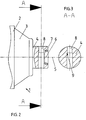
- eine Stirnseite von Fig. 1,
- Fig. 3
- einen Schnitt A-A von Fig. 2,
- Fig. 4
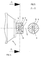
- eine weitere Stirnseite von Fig. 1,
- Fig. 5
- einen Schnitt A-A von Fig. 4,
- Fig. 6
- verschiedene Öffnungen (Schnitt),
- Fig. 7
- einen Druckmaschinenzylinder mit axialem Formschluss,
- Fig. 8
- einen Druckmaschinenzylinder mit umfangsseitigem Formschluss,
- Fig. 9
- einen Schnitt A-A von Fig. 8.
- Ein Druckmaschinenzylinder 1 weist einen Zylinderballen 2 mit zwei Stirnseiten auf. Die Stirnseiten sind bevorzugt mit einer in Seitengestellen angeordneten, zumindest einseitig antreibbaren, Lagerung zur Aufnahme des Druckmaschinenzylinders 1 koppelbar. Jede Stirnseite weist eine zur Zylinderachse 5 fluchtende Zentrierung 6, vorzugsweise eine kegelförmige oder zylindrische Zentrierung 6, auf. Die Zentrierungen 6 sind bei einer kegelförmigen Zentrierung 6 spiegelbildlich zueinander angeordnet. Die Zentrierungen 6 sind derart ausgebildet, dass von außen Zentriermittel, z.B. jeweils eine Pinole, in die Zentrierung 6 eingreifen können. Im vorliegenden Beispiel entspricht die Zylinderachse 5 in Einbaulage des Druckmaschinenzylinders 1 der Horizonzalen H.
- In den Figuren 1, 2 und 4 ist der Druckmaschinenzylinder 1 beispielhaft seitlich mit je einer Zylinderschulter 3 und je einem Zylinderzapfen 4 ausgebildet. Hierbei sind die Zentrierungen 6 endseitig in den Zylinderzapfen 4 des Druckmaschinenzylinders 1 angeordnet.
- In der Figur 1 ist jede Zentrierung 6 ohne Zentrierring 7, in den Figuren 2, 4, 7, 8 ist die Zentrierung 6 mit einem fixierten angeordneten, vorzugsweise unlösbar eingepassten, Zentrierring 7 (beidseitig) ausgebildet. Eine derartige unlösbare Verbindung ist beispielsweise durch eine Pressverbindung realisierbar. Die stirnseitig angeordneten Zentrierringe 7 dienen bevorzugt der Verschleißreduzierung an der Zentrierung 6 und sind beispielsweise gehärtet.
- Bei einer zylindrischen Zentrierung 6 ist der Zentrierring 7 zylindrisch, bei einer kegelförmigen Zentrierung 6 ist der Zentrierring 7 entsprechend kegelförmig ausgebildet. Alternativ ist in eine zylindrische Zentrierung 6 ein Zentrierring 7 mitkegelförmiger Innenfläche einsetzbar. Die Flächen des Zentrierringes 7 bzw. der Zentrierung 6 (Ausführung ohne Zentrierring 7) sind bevorzugt leicht ballig ausgeführt.
- Je nach Ausbildung des Druckmaschinenzylinders 1 sind die Zentrierungen 6 (mit oder ohne Zentrierring 7) - neben einer Anordnung in den Stirnseiten des Zylinderballens 2 - jeweils in einem Zylinderzapfen 4 oder einer Zylinderschulter 3 angeordnet.
- Der Druckmaschinenzylinder 1 weist in einer Weiterbildung stirnseitig je eine Öffnung 8 auf, welche mit Bezug auf die Zylinderachse 5 in einer Vertikalen V angeordnet ist. Bevorzugt ist die Öffnung 8 mit der Vertikalen V zentrisch zur Zylinderachse 5 angeordnet. Dabei ist die Öffnung 8 bevorzugt als Bohrung, z.B. als Durchgangs- oder Sackbohrung, ausgeführt. Jede Öffnung 8 weist bevorzugt wenigstens einen Rücksprung 9 auf, d.h. die Öffnung 8 ist in ihrer Größe wenigstens einfach gestuft angeordnet. Bei einer als Bohrung ausgebildeten Öffnung 8 ist diese Bohrung im Durchmesser gestuft.
- Je nach Ausbildung des Druckmaschinenzylinders 1 sind die Öffnungen 8 in den Stirnseiten des Zylinderballens 2 oder den Zylinderzapfen 4 oder der Zylinderschulter 3 angeordnet. Dabei sind die Öffnungen 8 separat oder in Kombination mit den Zentrierungen 6 im Bereich der Stirnseiten des Zylinderballens 2, der Zylinderschultern 3 bzw. der Zylinderzapfen 4 anordbar.
- Die Öffnungen 8 sind in Fig. 6 in verschiedenen Ausbildungen im Schnitt gezeigt, wobei die Öffnungen 8 in der Vertikalen V zentrisch zur Zylinderachse 5 angeordnet sind. Die Fig. 6 a entspricht der Fig. 3 und Fig. 6 b entspricht Fig. 5, wobei Fig. 6 c eine Weiterbildung von Fig. 3 ist. Die Öffnungen 8 weisen Durchgangsbohrungen auf, wobei Fig. 6 a einen Rücksprung 9, Fig. 6 b zwei von der Horizontalen H getrennte Rücksprünge 9 und Fig. 6 c einen die Horizontale H schneidenden Rücksprung 9 aufweist.
- Die Öffnungen 8 sind bevorzugt für die formschlüssige Verbindung mit der jeweiligen antreibbaren Lagerung und/oder als Aufnahmeöffnung für eine Anschlagvorrichtung, z.B. bei Austausch des Druckmaschinenzylinders 1, einsetzbar. Bevorzugt weisen die am Umfang austretenden Öffnungen 8 einen konischen Anfangsbereich auf, um den Formschluß mit der antreibbaren Lagerung und/oder einer Anschlagvorrichtung zu erleichtern.
- Wenigstens eine Stirnseite des Druckmaschinenzylinders 1 ist mit einem Freiraum 10 derart ausgebildet, dass eine lösbar, formschlüssige Verbindung mit der den Druckmaschinenzylinder 1 aufnehmenden Lagerung zwecks Übertragung des Drehmomentes auf den Druckmaschinenzylinder 1 realisierbar ist. Alternativ sind beide Stirnseiten mit einem Freiraum 10 ausgebildet.
- In Fig. 7 und 8 ist ein Druckmaschinenzylinder 1 stirnseitig in Einbaulage mit einer Lagerung gezeigt.
- Nach Fig. 7 ist am Druckmaschinenzylinder 1 die Öffnung 8 mit Rücksprung 9 als Sackbohrung für die Aufnahme eines Anschlagmittels ausgeführt und achsparallel zur Zylinderachse 5 weist der Druckmaschinenzylinder 1 (zusätzlich zur Zentrierung 6) einen Freiraum 10 für eine formschlüssige Verbindung, z.B. mittels einer Verriegelung 11, mit einer antreibbaren Lagerung auf.
- Gemäß Fig. 8 ist am Druckmaschinenzylinder 1 die Öffnung 8 als Durchgangsbohrung mit zwei Rücksprüngen 9 für die Aufnahme eines Anschlagmittels ausgeführt. Am Druckmaschinenzylinder 1 ist umfangsseitig ein umlaufender Freiraum 10 angeordnet, der beispielsweise als Gewinde oder Nut ausgebildet ist. Der Freiraum 10 weist bevorzugt eine sekantenförmige Anschlagfläche 12 auf, in die eine Platte als ortsfest am Lager angeordnete Verriegelung 11 formschlüssig eingreift.
- In einer Weiterbildung ist der Freiraum 10 für eine formschlüssige Verbindung zwecks Übertragung des Drehmomentes auch in der Zentrierung 6 anordbar.
- In einer nicht gezeigten weiteren Ausführung ist der mit wenigstens dem Zylinderballen 2 ausgebildete Druckmaschinenzylinder 1 in einer in den Seitengestellen angeordneten, antreibbaren Lagerung aufgenommen. An jeder der Stirnseiten weist der Druckmaschinenzylinder 1 je eine zur Zylinderachse 5 fluchtend angeordnete Zentrierung 6 auf. Am Druckmaschinenzylinder 1 ist wenigstens in einer Zentrierung 6 eine reibschlüssige Verbindung, vorzugsweise mit einem Zentriermittel, mit der antreibbaren Lagerung zwecks Übertragung des Drehmomentes realisierbar.
- In einer Weiterbildung ist im Bereich jeder Stirnseite ist eine zur Zylinderachse 5 in einer Vertikalen V verlaufende Öffnung 8 angeordnet, um eine Anschlagvorrichtung aufzunehmen. Eine weitere formschlüssige Kopplung mit einer antreibbaren Lagerung ist dabei nicht zwingend erforderlich.
- In dieser Ausführung ist die Zentrierung 6 zylindrisch oder kegelförmig ausgebildet, wobei bevorzugt in jeder Zentrierung 6 ein Zentrierring 7 fixierbar ist. Bei Ausbildung als kegelförmige Zentrierung 6 sind diese am Druckmaschinenzylinder 1 spiegelbildlich zueinander angeordnet. Die Zentrierungen 6 sind jeweils in einem Zylinderzapfen 4 oder einer Zylinderschulter 3 angeordnet. Die Öffnungen 8 sind bevorzugt zentrisch zur Zylinderachse 5 angeordnet. Ebenso weisen die Öffnungen 8 bevorzugt wenigstens einen Rücksprung 9 zur formschlüssigen Aufnahme einer Anschlagvorrichtung auf.
-
- 1
- Druckmaschinenzylinder
- 2
- Zylinderballen
- 3
- Zylinderschulter
- 4
- Zylinderzapfen
- 5
- Zylinderachse
- 6
- Zentrierung
- 7
- Zentrierring
- 8
- Öffnung (Bohrung)
- 9
- Rücksprung
- 10
- Freiraum
- 11
- Verriegelung
- 12
- Anschlagfläche
- H
- Horizontal
- V
- Vertikale
Claims (5)
- Druckmaschinenzylinder (1) mit einem Zylinderballen (2) und einer antreibbaren Lagerung zur Aufnahme des Druckmaschinenzylinders (1) in Seitengestellen einer Druckmaschine, mit- je einer zur Zylinderachse (5) fluchtend angeordneten Zentrierung (6) an jeder Stirnseite des Druckmaschinenzylinders (1),- einem zumindest an einer Stirnseite des Druckmaschinenzylinders (1) angeordneten Freiraum (10), welcher zumindest durch eine Anschlagfläche zur formschlüssigen Verbindung mit der antreibbaren Lagerung zwecks Übertragung des Drehmomentes begrenzt wird,dadurch gekennzeichnet,- dass die Zentrierung (6) an jeder Stirnseite des Druckmaschinenzylinders (1) als zur Stirnseite geöffnete Ausnehmung ausgebildet ist,- dass im Bereich jeder Stirnseite des Druckmaschinenzylinders (1) eine sich radial erstreckende und zentrisch zur Zylinderachse (5) angeordnete Öffnung (8) zur Aufnahme einer Anschlageinrichtung vorgesehen ist.
- Druckmaschinenzylinder nach Anspruch 1,
dadurch gekennzeichnet,
dass der Freiraum (10) parallel zur Zylinderachse (5) des Druckmaschinenzylinders (1) stirnseitig angeordnet ist, zwecks Aufnahme einer Verriegelung (11) der antreibbaren Lagerung. - Druckmaschinenzylinder nach Anspruch 1,
dadurch gekennzeichnet,
dass der Freiraum (10) umfangsseitig an der Stirnseite des Druckmaschinenzylinders (1) angeordnet ist, zwecks Aufnahme einer Verriegelung (11) der antreibbaren Lagerung. - Druckmaschinenzylinder nach Anspruch 3,
dadurch gekennzeichnet,
dass der Freiraum (10) eine umlaufende Nut oder ein Gewinde ist, und dass der Freiraum (10) eine sekantenförmige Anschlagfläche (12) aufweist, welche formschlüssig mit einer am Lager angeordneten Verriegelung (11) lösbar verbunden ist. - Druckmaschinenzylinder nach Anspruch 1,
dadurch gekennzeichnet,
dass die Öffnung (8) in ihrer Größe durch wenigstens einen Rücksprung (9) gestuft ist.
Applications Claiming Priority (2)
| Application Number | Priority Date | Filing Date | Title |
|---|---|---|---|
| DE19962419A DE19962419C2 (de) | 1999-12-22 | 1999-12-22 | Druckmaschinenzylinder |
| DE19962419 | 1999-12-22 |
Publications (2)
| Publication Number | Publication Date |
|---|---|
| EP1110726A1 EP1110726A1 (de) | 2001-06-27 |
| EP1110726B1 true EP1110726B1 (de) | 2006-10-18 |
Family
ID=7934099
Family Applications (1)
| Application Number | Title | Priority Date | Filing Date |
|---|---|---|---|
| EP00127630A Expired - Lifetime EP1110726B1 (de) | 1999-12-22 | 2000-12-16 | Druckmaschinenzylinder |
Country Status (4)
| Country | Link |
|---|---|
| EP (1) | EP1110726B1 (de) |
| AT (1) | ATE342802T1 (de) |
| DE (2) | DE19962419C2 (de) |
| DK (1) | DK1110726T3 (de) |
Families Citing this family (1)
| Publication number | Priority date | Publication date | Assignee | Title |
|---|---|---|---|---|
| DE10341850B4 (de) * | 2003-09-09 | 2007-05-03 | Windmöller & Hölscher Kg | Druckwerk mit schnell auswechselbarem Walzendorn einer Druck- oder Rasterwalze |
Family Cites Families (8)
| Publication number | Priority date | Publication date | Assignee | Title |
|---|---|---|---|---|
| FR703754A (fr) * | 1930-10-16 | 1931-05-06 | Manuf De Machines Modernes | Perfectionnements au montage des cylindres porte-cliché dans les machines à imprimer |
| DE624357C (de) * | 1933-03-04 | 1936-01-18 | Windmoeller & Hoelscher G M B | Befestigungsvorrichtung fuer Klischeezylinder von Druckmaschinen |
| US2925037A (en) * | 1956-12-07 | 1960-02-16 | Paul E Fischer | Apparatus for changing printing assembly |
| US2890517A (en) * | 1958-06-27 | 1959-06-16 | Magnat Machinery & Pattern Cor | Mechanism for securing roll to shaft |
| US3023699A (en) * | 1959-07-06 | 1962-03-06 | Macarthur Associates Inc | Printing cylinder mounting |
| DE1858031U (de) * | 1962-07-21 | 1962-09-06 | Windmoeller & Hoelscher | Vorrichtung in rotations-druckmaschinen zum tragen eines achslosen klischeezylinders. |
| US3205814A (en) * | 1964-09-24 | 1965-09-14 | William F Huck | Rotary cylinder construction of removable shell type |
| DE4328058A1 (de) * | 1993-08-20 | 1995-02-23 | Roland Man Druckmasch | Druckmaschine mit mindestens einem auswechselbaren Zylinder, insbesondere einem auswechselbaren Formzylinder, oder mit einer auswechselbaren Druckform |
-
1999
- 1999-12-22 DE DE19962419A patent/DE19962419C2/de not_active Expired - Fee Related
-
2000
- 2000-12-16 EP EP00127630A patent/EP1110726B1/de not_active Expired - Lifetime
- 2000-12-16 DK DK00127630T patent/DK1110726T3/da active
- 2000-12-16 DE DE50013630T patent/DE50013630D1/de not_active Expired - Lifetime
- 2000-12-16 AT AT00127630T patent/ATE342802T1/de active
Also Published As
| Publication number | Publication date |
|---|---|
| DK1110726T3 (da) | 2007-01-02 |
| DE50013630D1 (de) | 2006-11-30 |
| DE19962419C2 (de) | 2003-06-05 |
| EP1110726A1 (de) | 2001-06-27 |
| DE19962419A1 (de) | 2001-07-05 |
| ATE342802T1 (de) | 2006-11-15 |
Similar Documents
| Publication | Publication Date | Title |
|---|---|---|
| EP0894623B1 (de) | Druckwerk für eine Rollenrotationsdruckmaschine | |
| EP1242242B1 (de) | Verfahren und vorrichtung zum kuppeln/entkuppeln eines zylinders in einer druckmaschine | |
| EP3529197A1 (de) | Schnellwechselkupplung für eine behälterbehandlungsmaschine | |
| EP0864379B1 (de) | Klemmverbindung zwischen einem Spindelkopf und einem Walzenzapfen | |
| DE2734382C2 (de) | Zentriervorrichtung für einen Wellenzapfen in einer Gelenkwelle | |
| DE10008224B4 (de) | Vorrichtung zum Ein- und Ausbau eines Zylinders einer Druckmaschine | |
| EP0713023B1 (de) | Wellenkupplung | |
| EP1670600B1 (de) | Walzwerksantrieb mit einer ein- und entkoppeleinrichtung | |
| EP0124008A2 (de) | Vorrichtung zum Spannen von Druckplatten | |
| EP1276616A1 (de) | Vorrichtungen für registerhaltiges aufziehen eines aufzuges auf einen zylinder | |
| DE19731844A1 (de) | Vorrichtung zum Verbinden/Lösen eines Walzenkörpers in Rotationsdruckmaschinen | |
| EP1984181B1 (de) | Formzylinderankopplung | |
| DE19962419C2 (de) | Druckmaschinenzylinder | |
| DE4227643C2 (de) | Lagerung für Zylinder und Trommeln in Druckmaschinen | |
| DE19531840B4 (de) | Rotationsdruckmaschine | |
| EP2296892B1 (de) | Vorrichtung und verfahren zum ankoppeln einer farbübertragungswalze | |
| DE10106412B4 (de) | Direktbebildernde Mehrfarbenrotationsdruckmaschine | |
| DE3425610A1 (de) | Vorrichtung zur auswechselbaren befestigung eines kraftbetaetigten werkstueckhalters an der drehspindel einer werkzeugmaschine | |
| EP1277980B1 (de) | Gelenkwellenverbindung mit integrierter Beugenwinkelbegrenzung | |
| DE10341850B4 (de) | Druckwerk mit schnell auswechselbarem Walzendorn einer Druck- oder Rasterwalze | |
| DE10227448A1 (de) | Vorrichtung zur lösbaren Verbindung einer Motorantriebswelle und einer Zylinderwelle einer Rotationsdruckmaschine | |
| EP1530685A1 (de) | Anschlusselement zur verbindung von gelenkspindeln mit anschlussaggregaten, insbesondere trefferhalterung mit konischer zentrierung | |
| EP3116666B1 (de) | Spielfreie welle-nabe-verbindung, zapfenaufnehmer und antriebsordnung mit einer derartigen spielfreien welle-nabe-verbindung | |
| DE19509921A1 (de) | Spanneinrichtung zum Spannen großer und/oder schwerer Werkstücke mit zylindrischen Aufnahmeflächen | |
| DE1290380B (de) | Walze mit auswechselbarem Walzenkoerper |
Legal Events
| Date | Code | Title | Description |
|---|---|---|---|
| PUAI | Public reference made under article 153(3) epc to a published international application that has entered the european phase |
Free format text: ORIGINAL CODE: 0009012 |
|
| AK | Designated contracting states |
Kind code of ref document: A1 Designated state(s): AT BE CH CY DE DK ES FI FR GB GR IE IT LI LU MC NL PT SE TR |
|
| AX | Request for extension of the european patent |
Free format text: AL;LT;LV;MK;RO;SI |
|
| 17P | Request for examination filed |
Effective date: 20010516 |
|
| AKX | Designation fees paid |
Free format text: AT BE CH CY DE DK ES FI FR GB GR IE IT LI LU MC NL PT SE TR |
|
| GRAP | Despatch of communication of intention to grant a patent |
Free format text: ORIGINAL CODE: EPIDOSNIGR1 |
|
| GRAS | Grant fee paid |
Free format text: ORIGINAL CODE: EPIDOSNIGR3 |
|
| GRAA | (expected) grant |
Free format text: ORIGINAL CODE: 0009210 |
|
| AK | Designated contracting states |
Kind code of ref document: B1 Designated state(s): AT BE CH CY DE DK ES FI FR GB GR IE IT LI LU MC NL PT SE TR |
|
| PG25 | Lapsed in a contracting state [announced via postgrant information from national office to epo] |
Ref country code: NL Free format text: LAPSE BECAUSE OF FAILURE TO SUBMIT A TRANSLATION OF THE DESCRIPTION OR TO PAY THE FEE WITHIN THE PRESCRIBED TIME-LIMIT Effective date: 20061018 Ref country code: IE Free format text: LAPSE BECAUSE OF FAILURE TO SUBMIT A TRANSLATION OF THE DESCRIPTION OR TO PAY THE FEE WITHIN THE PRESCRIBED TIME-LIMIT Effective date: 20061018 Ref country code: FI Free format text: LAPSE BECAUSE OF FAILURE TO SUBMIT A TRANSLATION OF THE DESCRIPTION OR TO PAY THE FEE WITHIN THE PRESCRIBED TIME-LIMIT Effective date: 20061018 |
|
| REG | Reference to a national code |
Ref country code: GB Ref legal event code: FG4D Free format text: NOT ENGLISH |
|
| REG | Reference to a national code |
Ref country code: IE Ref legal event code: FG4D Free format text: LANGUAGE OF EP DOCUMENT: GERMAN Ref country code: CH Ref legal event code: EP |
|
| REF | Corresponds to: |
Ref document number: 50013630 Country of ref document: DE Date of ref document: 20061130 Kind code of ref document: P |
|
| PG25 | Lapsed in a contracting state [announced via postgrant information from national office to epo] |
Ref country code: BE Free format text: LAPSE BECAUSE OF NON-PAYMENT OF DUE FEES Effective date: 20061231 Ref country code: MC Free format text: LAPSE BECAUSE OF NON-PAYMENT OF DUE FEES Effective date: 20061231 Ref country code: LI Free format text: LAPSE BECAUSE OF NON-PAYMENT OF DUE FEES Effective date: 20061231 Ref country code: CH Free format text: LAPSE BECAUSE OF NON-PAYMENT OF DUE FEES Effective date: 20061231 |
|
| REG | Reference to a national code |
Ref country code: DK Ref legal event code: T3 |
|
| PG25 | Lapsed in a contracting state [announced via postgrant information from national office to epo] |
Ref country code: SE Free format text: LAPSE BECAUSE OF FAILURE TO SUBMIT A TRANSLATION OF THE DESCRIPTION OR TO PAY THE FEE WITHIN THE PRESCRIBED TIME-LIMIT Effective date: 20070118 |
|
| PG25 | Lapsed in a contracting state [announced via postgrant information from national office to epo] |
Ref country code: ES Free format text: LAPSE BECAUSE OF FAILURE TO SUBMIT A TRANSLATION OF THE DESCRIPTION OR TO PAY THE FEE WITHIN THE PRESCRIBED TIME-LIMIT Effective date: 20070129 |
|
| PG25 | Lapsed in a contracting state [announced via postgrant information from national office to epo] |
Ref country code: PT Free format text: LAPSE BECAUSE OF FAILURE TO SUBMIT A TRANSLATION OF THE DESCRIPTION OR TO PAY THE FEE WITHIN THE PRESCRIBED TIME-LIMIT Effective date: 20070319 |
|
| NLV1 | Nl: lapsed or annulled due to failure to fulfill the requirements of art. 29p and 29m of the patents act | ||
| ET | Fr: translation filed | ||
| GBV | Gb: ep patent (uk) treated as always having been void in accordance with gb section 77(7)/1977 [no translation filed] |
Effective date: 20061018 |
|
| REG | Reference to a national code |
Ref country code: IE Ref legal event code: FD4D |
|
| REG | Reference to a national code |
Ref country code: CH Ref legal event code: PL |
|
| PLBE | No opposition filed within time limit |
Free format text: ORIGINAL CODE: 0009261 |
|
| STAA | Information on the status of an ep patent application or granted ep patent |
Free format text: STATUS: NO OPPOSITION FILED WITHIN TIME LIMIT |
|
| 26N | No opposition filed |
Effective date: 20070719 |
|
| PG25 | Lapsed in a contracting state [announced via postgrant information from national office to epo] |
Ref country code: GB Free format text: LAPSE BECAUSE OF FAILURE TO SUBMIT A TRANSLATION OF THE DESCRIPTION OR TO PAY THE FEE WITHIN THE PRESCRIBED TIME-LIMIT Effective date: 20061018 |
|
| BERE | Be: lapsed |
Owner name: MAN ROLAND DRUCKMASCHINEN A.G. Effective date: 20061231 |
|
| PG25 | Lapsed in a contracting state [announced via postgrant information from national office to epo] |
Ref country code: GR Free format text: LAPSE BECAUSE OF FAILURE TO SUBMIT A TRANSLATION OF THE DESCRIPTION OR TO PAY THE FEE WITHIN THE PRESCRIBED TIME-LIMIT Effective date: 20070119 |
|
| PG25 | Lapsed in a contracting state [announced via postgrant information from national office to epo] |
Ref country code: TR Free format text: LAPSE BECAUSE OF FAILURE TO SUBMIT A TRANSLATION OF THE DESCRIPTION OR TO PAY THE FEE WITHIN THE PRESCRIBED TIME-LIMIT Effective date: 20061018 Ref country code: LU Free format text: LAPSE BECAUSE OF NON-PAYMENT OF DUE FEES Effective date: 20061216 |
|
| PG25 | Lapsed in a contracting state [announced via postgrant information from national office to epo] |
Ref country code: CY Free format text: LAPSE BECAUSE OF FAILURE TO SUBMIT A TRANSLATION OF THE DESCRIPTION OR TO PAY THE FEE WITHIN THE PRESCRIBED TIME-LIMIT Effective date: 20061018 |
|
| REG | Reference to a national code |
Ref country code: FR Ref legal event code: CD |
|
| PGFP | Annual fee paid to national office [announced via postgrant information from national office to epo] |
Ref country code: DK Payment date: 20091214 Year of fee payment: 10 |
|
| PGFP | Annual fee paid to national office [announced via postgrant information from national office to epo] |
Ref country code: FR Payment date: 20100108 Year of fee payment: 10 |
|
| PGFP | Annual fee paid to national office [announced via postgrant information from national office to epo] |
Ref country code: AT Payment date: 20101214 Year of fee payment: 11 |
|
| PGFP | Annual fee paid to national office [announced via postgrant information from national office to epo] |
Ref country code: IT Payment date: 20101227 Year of fee payment: 11 |
|
| REG | Reference to a national code |
Ref country code: DK Ref legal event code: EBP |
|
| REG | Reference to a national code |
Ref country code: FR Ref legal event code: ST Effective date: 20110831 |
|
| PG25 | Lapsed in a contracting state [announced via postgrant information from national office to epo] |
Ref country code: FR Free format text: LAPSE BECAUSE OF NON-PAYMENT OF DUE FEES Effective date: 20110103 |
|
| REG | Reference to a national code |
Ref country code: DE Ref legal event code: R081 Ref document number: 50013630 Country of ref document: DE Owner name: MANROLAND SHEETFED GMBH, DE Free format text: FORMER OWNER: MANROLAND AG, 63075 OFFENBACH, DE Effective date: 20120509 |
|
| PG25 | Lapsed in a contracting state [announced via postgrant information from national office to epo] |
Ref country code: IT Free format text: LAPSE BECAUSE OF NON-PAYMENT OF DUE FEES Effective date: 20111216 |
|
| REG | Reference to a national code |
Ref country code: AT Ref legal event code: MM01 Ref document number: 342802 Country of ref document: AT Kind code of ref document: T Effective date: 20111216 |
|
| PG25 | Lapsed in a contracting state [announced via postgrant information from national office to epo] |
Ref country code: AT Free format text: LAPSE BECAUSE OF NON-PAYMENT OF DUE FEES Effective date: 20111216 |
|
| PGFP | Annual fee paid to national office [announced via postgrant information from national office to epo] |
Ref country code: DE Payment date: 20161213 Year of fee payment: 17 |
|
| REG | Reference to a national code |
Ref country code: DE Ref legal event code: R119 Ref document number: 50013630 Country of ref document: DE |
|
| PG25 | Lapsed in a contracting state [announced via postgrant information from national office to epo] |
Ref country code: DE Free format text: LAPSE BECAUSE OF NON-PAYMENT OF DUE FEES Effective date: 20180703 |