EP1109680B1 - Pneumatic driver tire for tracked vehicle - Google Patents
Pneumatic driver tire for tracked vehicle Download PDFInfo
- Publication number
- EP1109680B1 EP1109680B1 EP98944647A EP98944647A EP1109680B1 EP 1109680 B1 EP1109680 B1 EP 1109680B1 EP 98944647 A EP98944647 A EP 98944647A EP 98944647 A EP98944647 A EP 98944647A EP 1109680 B1 EP1109680 B1 EP 1109680B1
- Authority
- EP
- European Patent Office
- Prior art keywords
- tread
- tire
- lugs
- lug
- sidewall
- Prior art date
- Legal status (The legal status is an assumption and is not a legal conclusion. Google has not performed a legal analysis and makes no representation as to the accuracy of the status listed.)
- Expired - Lifetime
Links
Images


Classifications
-
- B—PERFORMING OPERATIONS; TRANSPORTING
- B60—VEHICLES IN GENERAL
- B60C—VEHICLE TYRES; TYRE INFLATION; TYRE CHANGING; CONNECTING VALVES TO INFLATABLE ELASTIC BODIES IN GENERAL; DEVICES OR ARRANGEMENTS RELATED TO TYRES
- B60C11/00—Tyre tread bands; Tread patterns; Anti-skid inserts
- B60C11/03—Tread patterns
- B60C11/0311—Patterns comprising tread lugs arranged parallel or oblique to the axis of rotation
- B60C11/0316—Patterns comprising tread lugs arranged parallel or oblique to the axis of rotation further characterised by the groove cross-section
-
- B—PERFORMING OPERATIONS; TRANSPORTING
- B60—VEHICLES IN GENERAL
- B60C—VEHICLE TYRES; TYRE INFLATION; TYRE CHANGING; CONNECTING VALVES TO INFLATABLE ELASTIC BODIES IN GENERAL; DEVICES OR ARRANGEMENTS RELATED TO TYRES
- B60C11/00—Tyre tread bands; Tread patterns; Anti-skid inserts
- B60C11/03—Tread patterns
- B60C11/0311—Patterns comprising tread lugs arranged parallel or oblique to the axis of rotation
Definitions
- the present invention relates to tracked vehicles for agricultural vehicles and the like, more particularly a pneumatic drive tire and wheel for such tracked vehicles.
- track vehicles for agricultural use.
- These track vehicles use an endless belt, preferably made of elastomeric material reinforced by cords of steel.
- the belt has a ground engaging tread surface similar to that found on a tire.
- the primary benefit to a track system is clearly the increase flotation tracks have over tires. Tracks can bridge a longer surface area, helping to keep the vehicle afloat. In many agricultural applications the use of tracked vehicles is becoming ever increasingly more popular.
- U.S. Patent No. 5,279,378 to Charles E. Grawey, et al. a frictionally driven belted work vehicle is disclosed.
- Grawey discloses the use of a metal-coated wheel assembly having a pair of rigid wheels with a rubber coating as a drive wheel.
- a cushion wheel can be used as a drive wheel and in an alternative embodiment a bias belted pneumatic tire is used in pairs to provide a drive wheel for the belted vehicle.
- Grawey et al. advises that the metal or cushioned wheels are preferred over the pneumatic wheels for a variety of reasons.
- DE-B- 1 009 954 discloses a tire suitable for a tracked vehicle having a plurality of lugs divided in two rows, the rows of lugs extending from each sidewall to the tread center plane.
- WO-A- 98/33669 discloses a tire for industrial service application having a plurality of lugs extending radially outwardly from the inner tread base. A first and second row of lugs extend from each of the tread shoulders and a central row is positioned between the first and second row.
- the pneumatic wheel can be used which can accommodate debris and wet soil conditions while still maintain frictional engagement with the belt itself so that forward or reverse propulsion of the vehicle is not dramatically reduced due to a wet or muddy soil condition.
- the present invention relates to a pneumatic drive tire (10) for track vehicles.
- the tire (10) has a carcass reinforcing structure (30) having two or more bias angled plies (32, 34).
- the cords of the first ply (32) are oppositely oriented relative to the cords of the second ply (34).
- the tire (10) has no belts or breakers and preferably has an aspect ratio of 100%.
- the tire (10) has tread (12) with voids that extend across the entire tread creating soil discharge channels (70).
- the tire tread (12) has a central area (66) exhibiting high contact area and axially outer areas (60, 62) having a lower contact area.
- the tread lugs (40) also have a radius portion (48) designed to limit the tire sidewalls (16) from contacting the track (2).
- Each tire (10) has a pair of annular beads (24), a carcass reinforcing structure (30) extending radially outward from bead (24) to bead (24), an elastomeric sidewall (16) extending radially outward from each bead (24) adjacent the carcass reinforcing structure (30) to a radially outer tread (12).
- the tread (12) is characterized by an inner tread surface (14), a plurality of lugs (40) extending radially outward from the inner tread (14) a distance (h).
- the lugs (40) are divided into a first row and a second row. The first row extends from the sidewall (16) toward the center plane of the tread.
- the second row extends from the opposite sidewall toward the center plane of the tread (12).
- the lugs (40) from the first row are circumferentially offset and similar in shape but oppositely oriented relative to the lugs (40) of the second row.
- Each lug (40) has an enlarged axially inner end (46).
- a shallow circumferentially continuous central rib (50) extends radially outward from the inner tread (14) a distance of less than half (h).
- a combination of lugs (40), inner tread (14) and a shallow central continuous rib (50) are spaced to create voids of continuous soil discharge channels (70) extending across the tread (12) from sidewall (16) to opposite sidewall (16).
- the tread (12) is divided into three parts (60, 62, 66).
- a first axially outer portion (60) being 1/6 of the tread width.
- a second axially outer portion (62) being 1/6 of the tread width and a central portion (66) of 2/3 of the tread width.
- Each portion (60, 62, 66) has a net contact area measured around the circumference of the tire (10).
- the contact area of the first tire portion (60) and the second portion (62) is less than 60% of the gross circumferential area of the respective portion.
- the central portion (66) has a net contact area about 60%.
- the outer portions (60, 62) had a net contact area 52% while the net contact area of the central portion was approximately 60%.
- each lug (40) has an axially outer surface (42) tangent to a sidewall (16) extending generally radially outwardly therefrom, the radially outer surface (44) of circumferentially adjacent lugs (40) are spaced by the soil discharge channel (70) preferably the radially outer surface (44) joins the axially outer surface (42) at a radius portion (48).
- the radius portion (48) is less than the radius of the central guide of the track thereby minimizing the contact of the axially outer portion (42) of the lug (40) and sidewall (16) with the track (2).
- the lugs (40) extend radially from the central rib (50) a distance of less than half of an inch (2 cm), the central rib (50) extends outwardly less than a quarter of an inch (1 cm), the total distance (h) being less than .75 inches (3 cm).
- the lugs (40) each have a centerline (41) as measured between the leading edges (43) and the trailing edges (45) of the respective lug.
- the centerline (41) being about 90° relative of the circumferential direction.
- a vehicle (1) is shown with its associated track (2) and drive wheel assembly (4).
- the vehicle (1) has a forward and rear drive wheel position which is entrained by the track.
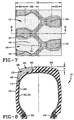
- Each drive wheel position has two wheels (4) as further illustrated in the cross-sectional view of FIGURE 2.
- These tracks (2) have integral guide lugs (5) that are aligned in the circumferential direction and traverse between each pair of drive wheels (4).
- These guide lugs (5) prevent the track (2) from slipping over the ends of the wheels (4).
- the track (2) has a rubberized tread (3) with cross bars or lugs (6) placed in a directional pattern as shown. No additional supporting structures or grossers are used in the application as shown.
- the pneumatic tires (10) provide the spring rate for the vehicle (1) and provide its cushioning such that the vehicle (1) can be provided without complex suspension system.
- the track (2) is reinforced by cords (7) running along a circumferential direction track (2).
- the wheel assembly (4) rides on each side of the guide lugs (5) along a smooth surface of the interior of the track.
- the tire (10) has a pair of bead cores (24).
- the bead cores (24) are substantially inextensible for preferably made of steel.
- a carcass reinforcing structure (30) extends from bead core (24) to bead core (24) as shown.
- the carcass reinforcing structure (30) has two or more plies, a first ply (32) and a second ply (34). Each ply (32, 34) is reinforced with cords.
- the cords of the first ply (32) being equal but oppositely oriented relative to cords of the second ply (34).
- Each ply structure (32, 34) as shown has a turns up which wraps about the bead core (24).
- Adjacent to the bead core (24) is a pair of sidewall structures (16).
- the sidewall structures (16) are generally elastomeric and extend from the beads (24) toward the tread (12).
- the tread (12) has a radially inner tread surface (14) and a plurality of tread lugs (40) extending from the radially inner tread surface (14) outwardly.
- the tread lugs (40) have an axially outer surface (42) and a radially outer surface (44). Disposed in this center portion of the tread (12) is shallow continuous rib (50).
- the tread (12) is divided into axially outer portions (60) and (62) and a central portion (66).
- the outer portions are each 1/6 of the tread width whereas the central portion represents 2/3 of the tread width as illustrated.
- the axially outer portions (60, 62) have a net contact area as measured around the circumference of the tire (10) of approximately 52%.
- the central 2/3 portion of the tread as identified by reference numeral (66) has a contact area of substantially 60%.
- the shallow rib (50) is occupied entirely within the central portion (66) of the tread (12).
- the enlarged lug head (46) at the axially inner end of each lug (40) is located entirely within the central portion (66) of the tread (12).
- each tread lug (40) has a lug centerline (41) which lies substantially 90° to the circumferential direction of the tire (10).
- Each lug (40) as shown in FIGURE 8 has a total depth of approximately h as measured at the equatorial plane.
- the lug height h includes the radial thickness of shallow rib (50) which extends above the inner surface (14) of the tread (12) distance of less than one half inch (2 cm).
- This shallow rib (50) provides additional bracing support for the lugs (40) and maintains the center of the tire (10) in a more rigid circumferential resistance to hoop deflection when employed with the circumferentially offset lugs (40) of the first and second rows.
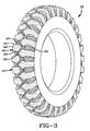
- FIGURE 3 a perspective view of the tire (10) is shown.
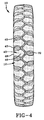
- the tread pattern is further shown in FIGURE 4 in the plane view; it is important to note that the tires (10) are extremely small in section width in some cases having a total section width of less than 4 inches (16 cm).
- the tire (10) has a size 4.00-16sl and as aspect ratio of 101%.
- the tire (10) has a section width of 6 inches (24 cm) and a 16 inch (40 cm) nominal rim diameter and an aspect ratio of 103%.
- the tread width is naturally slightly smaller than the section width of the tire (10) which means that the entire tractive force of the drive tire must be achieved by the tread (12) over a very narrow width.
- the lug non-skid distance or lug height h is approximately .635 inches (1.6 cm).
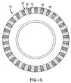
- FIGURE 5 a side view of the tire (10) it can be seen that the soil discharge channel (70) extends clearly down the sidewall (16) of the tire (10) a substantial distance and that the axially outer portion (42) of the tread lugs (40) similarly extend a reasonable distance down the sidewall of the tire (10).
- each lug (40) has a generous radius (48) joining the axially outer portion (42) of the lug (40) with the radially outer surface (44) of each lug (40). It is believed preferable that this radius (48) be less than the radius of track (2) to which the tire (10) is to be mounted.
- this relationship is achieved the tire (10) is able to reasonably come in contact with the guide lug (5) at the radius of the guide lug (5) and the inner surface of the track (2) such that the tire sidewalls (16) generally are free of contact from the guide lugs (5) of the track (2) except under severe lateral loads. This prevents the tire (10) from wearing in the fashion that a V-belt would wear on a pulley.
- the center portion (66) of the tread (12) must carry primary driving traction capability of the tire (10), therefore, a high contact area with sufficient grooving must be provided so that the tire (10) does not slip when internal surface of the track (2) and the tread (12) of the tire wheel assembly become lubricated with mud or wet sloppy soil.
- the tires (10) are designed such that they have minimum tread width. While it believed that the tire (10) of the present invention requires no restrictive belts or breakers it is understood that they could be added if one so desired without losing the beneficial traction features of the tread (12) as described above. However it is believed that the belt or breakers are considered to be an unnecessary feature of the tire (10) when constructed in a bias carcass reinforcing structure as described above.
- the tire (10) when manufactured as described above has a relatively low non-skid depth with a relatively high net contact area in the tread (12).
- the tire (10) being of relatively narrow section width and of sufficiently small diameter is extremely light weight in size and yet very durable for the application.
- the continuous channels (70) across the tread (12) provide excellent debris discharge capability and the fact that the lugs (40) of the first row are circumferentially offset from the lugs of the second row enable the tire (10) to maintain good uniform ride characteristics greatly reducing any vibration induced harmonics which further enhances the ride performance of the vehicle (1).
- the pneumatic tire (10) of the present invention provides an increase in surface traction to the belt or track (2) such that it is an acceptable alternative for medium to light weight vehicles which greatly reduces the overall cost of employ a tracked system.
Landscapes
- Engineering & Computer Science (AREA)
- Mechanical Engineering (AREA)
- Tires In General (AREA)
Description
The central portion (66) has a net contact area about 60%. In the preferred embodiment the outer portions (60, 62) had a net contact area 52% while the net contact area of the central portion was approximately 60%.
The pneumatic tires (10) provide the spring rate for the vehicle (1) and provide its cushioning such that the vehicle (1) can be provided without complex suspension system. The track (2) is reinforced by cords (7) running along a circumferential direction track (2). The wheel assembly (4) rides on each side of the guide lugs (5) along a smooth surface of the interior of the track.
Claims (7)
- A pneumatic drive tire (10) for a tracked vehicle (1) having a pair of annular beads (24), a carcass reinforcing structure (34) extending radially outwardly from bead (24) to bead (24), an elastomeric sidewall (16) extending radially outwardly from each bead (22) adjacent the carcass reinforcing structure (30) to a radially outer tread (12), an inner tread (14) a plurality of lugs (40) extending radially outwardly from the inner tread surface (14) a distance (h), the lugs (40) being divided into a first row and a second row, the first row extending from the sidewall (16) toward the center plane of the tread (12), the second row extending from the opposite sidewall (16) toward the center plane of the tread (12), the lugs (40) of the first row being circumferentially offset and similar in shape but oppositely oriented relative to the lugs (40) of the second row, each lug (40) having an enlarged axially inner end (46), wherein the combination of lugs (40), inner tread surface (14) are spaced to create voids of continuous soil discharge channels (70) extending across the tread (12) from sidewall (16) to opposite sidewall (16); the tread (12) being characterized by
a shallow circumferentially continuous center rib (50) extending radially outwardly from the inner tread surface (14) a distance of less than half said distance (h) the lugs (40) extend radially outwardly from the inner tread surface; and
wherein the combination of lugs (40), inner tread surface (14) and a shallow central continuous rib (5) are spaced to create said voids of continuous soil discharge channels (70). - The pneumatic drive tire (10) for a tracked vehicle (1) of claim 1 wherein the tread (12) is divided into three parts, a first outer portion (60) being 1/6 of the tread width, a second outer portion (62) being 1/6 of the tread width and a central portion (66) being 2/3 of the tread width, each portion (60, 62, 66) has a net contact area so measured around the circumference of the tire, the contact area of the first outer portion (60) and the second outer portion (62) is less than 60% of the gross circumferential area of the respective portion, the central portion (66) has a net contact area above 60%.
- The pneumatic drive tire (10) for a tracked vehicle (1) of claim 1 further characterized by an aspect ratio of about 100%, the aspect ratio being defined as the tire section height divided by the tire section width.
- The pneumatic drive tire (10) for a tracked vehicle (1) of claim 1 wherein each lug (40) has an axially outer surface (42) tangent to a sidewall (16) and extending generally radially outwardly therefrom to a radially outer surface (44), the radially outer surfaces (44) of circumferentially adjacent lugs (40) being spaced by the soil discharge channel (70).
- The pneumatic drive tire (10) for a tracked vehicle (1) of claim 1 wherein the lug (40) extends radially from the central rib (50) a distance less than 0.5 inch (1.3 cm), the central rib extends outwardly less than 0.25 inch (.6 cm), the total distance (h) being less than a 0.75 inches (1.9 cm).
- The pneumatic drive tire (10) for a tracked vehicle (1) of claim 4 wherein each lug (40) has a radius portion (48) joining the radially outer surface (44) and the axially outer portion (42), the radius portion (48) being less then the radius of the central guide of the track (2) to which the tire (10) is driving, thereby minimizing the contact of the axially outer portion (42) of the lug (40) and the sidewall (16) with the track (2).
- The pneumatic drive tire (10) for a tracked vehicle (1) of claim 1 wherein the lugs (40) each have a centerline (41) as measured between leading edges (43) and trailing edges (45) of the lug (40) the centerline (41) being about 90° relative to the circumferential direction of the tire.
Applications Claiming Priority (1)
| Application Number | Priority Date | Filing Date | Title |
|---|---|---|---|
| PCT/US1998/018131 WO2000013921A1 (en) | 1998-09-02 | 1998-09-02 | Pneumatic driver tire for tracked vehicle |
Publications (2)
| Publication Number | Publication Date |
|---|---|
| EP1109680A1 EP1109680A1 (en) | 2001-06-27 |
| EP1109680B1 true EP1109680B1 (en) | 2004-08-25 |
Family
ID=22267799
Family Applications (1)
| Application Number | Title | Priority Date | Filing Date |
|---|---|---|---|
| EP98944647A Expired - Lifetime EP1109680B1 (en) | 1998-09-02 | 1998-09-02 | Pneumatic driver tire for tracked vehicle |
Country Status (5)
| Country | Link |
|---|---|
| EP (1) | EP1109680B1 (en) |
| JP (1) | JP4464562B2 (en) |
| AU (1) | AU9214298A (en) |
| DE (1) | DE69825918T2 (en) |
| WO (1) | WO2000013921A1 (en) |
Families Citing this family (4)
| Publication number | Priority date | Publication date | Assignee | Title |
|---|---|---|---|---|
| CA2329445A1 (en) * | 1999-12-22 | 2001-06-22 | Fbt Enterprises, Inc. | High bead ratio tire |
| US6688355B2 (en) * | 2001-05-31 | 2004-02-10 | The Boodyear Tire & Rubber Company | Three piece tire assembly |
| KR100806020B1 (en) * | 2004-05-11 | 2008-02-26 | 현대중공업 주식회사 | The rubber endless track that can cover steel crawler for preserve road |
| US9108469B2 (en) | 2007-10-01 | 2015-08-18 | Bridgestone Americas Tire Operations, Llc | Irrigation tire |
Family Cites Families (6)
| Publication number | Priority date | Publication date | Assignee | Title |
|---|---|---|---|---|
| DE1009954B (en) * | 1954-12-14 | 1957-06-06 | Heinrich Speiser Dr | Tires, especially for all-terrain vehicles |
| NL135522B (en) * | 1965-07-31 | |||
| JPS5237844B2 (en) * | 1974-04-23 | 1977-09-26 | ||
| JPS61500720A (en) * | 1983-12-20 | 1986-04-17 | キヤタピラ− トラクタ− カンパニ− | Friction driven track type work vehicle |
| JPH0687304A (en) * | 1992-09-03 | 1994-03-29 | Sumitomo Rubber Ind Ltd | Bias tire for construction vehicle |
| DE69709405T2 (en) * | 1997-02-04 | 2002-10-17 | The Goodyear Tire & Rubber Co., Akron | INDUSTRIAL AGRICULTURAL TIRE |
-
1998
- 1998-09-02 AU AU92142/98A patent/AU9214298A/en not_active Abandoned
- 1998-09-02 EP EP98944647A patent/EP1109680B1/en not_active Expired - Lifetime
- 1998-09-02 JP JP2000568700A patent/JP4464562B2/en not_active Expired - Fee Related
- 1998-09-02 DE DE69825918T patent/DE69825918T2/en not_active Expired - Fee Related
- 1998-09-02 WO PCT/US1998/018131 patent/WO2000013921A1/en active IP Right Grant
Also Published As
| Publication number | Publication date |
|---|---|
| AU9214298A (en) | 2000-03-27 |
| DE69825918D1 (en) | 2004-09-30 |
| DE69825918T2 (en) | 2005-09-08 |
| EP1109680A1 (en) | 2001-06-27 |
| JP4464562B2 (en) | 2010-05-19 |
| WO2000013921A1 (en) | 2000-03-16 |
| JP2002524328A (en) | 2002-08-06 |
Similar Documents
| Publication | Publication Date | Title |
|---|---|---|
| US6386652B1 (en) | Pneumatic driver tire for tracked vehicle | |
| JP4246381B2 (en) | Industrial pneumatic tires | |
| US5361814A (en) | Asymmetric tire | |
| KR960011995B1 (en) | Pneumatic tire | |
| US5464050A (en) | Non-directional pneumatic tire for use on agricultural tractors and other like vehicles | |
| US6192953B1 (en) | Heavy duty radial tire having tapered shoulder portions | |
| CA1284935C (en) | All-terrain pneumatic tire | |
| US4926919A (en) | Vehicle tire with rib type tread pattern having sipes across the ribs | |
| US7134467B2 (en) | Low net to gross OTR tire | |
| US6209602B1 (en) | Industrial service agricultural tire | |
| JP2002528334A (en) | Tires and tire treads | |
| AU2023229557A1 (en) | Heavy duty tyre and tread | |
| US6021829A (en) | All-terrain-vehicle tire | |
| US4574857A (en) | Tractor tire tread | |
| EP1109680B1 (en) | Pneumatic driver tire for tracked vehicle | |
| EP0958151B1 (en) | Industrial service agricultural tire | |
| JP4451585B2 (en) | All-terrain vehicle tire | |
| CA2261043C (en) | An all-terrain-vehicle tire | |
| CA2508902C (en) | Pneumatic driver tire for tracked vehicle | |
| JP3467084B2 (en) | Pneumatic radial tire | |
| EP0921955A1 (en) | Industrial service agricultural tire | |
| FI109006B (en) | Pneumatic tyre | |
| KR20000023794A (en) | An all-terrain-vehicle tire |
Legal Events
| Date | Code | Title | Description |
|---|---|---|---|
| PUAI | Public reference made under article 153(3) epc to a published international application that has entered the european phase |
Free format text: ORIGINAL CODE: 0009012 |
|
| 17P | Request for examination filed |
Effective date: 20010402 |
|
| AK | Designated contracting states |
Kind code of ref document: A1 Designated state(s): DE FR GB |
|
| GRAP | Despatch of communication of intention to grant a patent |
Free format text: ORIGINAL CODE: EPIDOSNIGR1 |
|
| GRAS | Grant fee paid |
Free format text: ORIGINAL CODE: EPIDOSNIGR3 |
|
| GRAA | (expected) grant |
Free format text: ORIGINAL CODE: 0009210 |
|
| AK | Designated contracting states |
Kind code of ref document: B1 Designated state(s): DE FR GB |
|
| REG | Reference to a national code |
Ref country code: GB Ref legal event code: FG4D |
|
| REF | Corresponds to: |
Ref document number: 69825918 Country of ref document: DE Date of ref document: 20040930 Kind code of ref document: P |
|
| ET | Fr: translation filed | ||
| PLBE | No opposition filed within time limit |
Free format text: ORIGINAL CODE: 0009261 |
|
| STAA | Information on the status of an ep patent application or granted ep patent |
Free format text: STATUS: NO OPPOSITION FILED WITHIN TIME LIMIT |
|
| 26N | No opposition filed |
Effective date: 20050526 |
|
| PGFP | Annual fee paid to national office [announced via postgrant information from national office to epo] |
Ref country code: FR Payment date: 20060922 Year of fee payment: 8 |
|
| REG | Reference to a national code |
Ref country code: FR Ref legal event code: ST Effective date: 20070831 |
|
| PGFP | Annual fee paid to national office [announced via postgrant information from national office to epo] |
Ref country code: GB Payment date: 20070809 Year of fee payment: 10 |
|
| PGFP | Annual fee paid to national office [announced via postgrant information from national office to epo] |
Ref country code: DE Payment date: 20070928 Year of fee payment: 10 |
|
| PG25 | Lapsed in a contracting state [announced via postgrant information from national office to epo] |
Ref country code: FR Free format text: LAPSE BECAUSE OF NON-PAYMENT OF DUE FEES Effective date: 20061002 |
|
| GBPC | Gb: european patent ceased through non-payment of renewal fee |
Effective date: 20080902 |
|
| PG25 | Lapsed in a contracting state [announced via postgrant information from national office to epo] |
Ref country code: DE Free format text: LAPSE BECAUSE OF NON-PAYMENT OF DUE FEES Effective date: 20090401 |
|
| PG25 | Lapsed in a contracting state [announced via postgrant information from national office to epo] |
Ref country code: GB Free format text: LAPSE BECAUSE OF NON-PAYMENT OF DUE FEES Effective date: 20080902 |