EP1109204A2 - Compact equipment - Google Patents
Compact equipment Download PDFInfo
- Publication number
- EP1109204A2 EP1109204A2 EP20000311168 EP00311168A EP1109204A2 EP 1109204 A2 EP1109204 A2 EP 1109204A2 EP 20000311168 EP20000311168 EP 20000311168 EP 00311168 A EP00311168 A EP 00311168A EP 1109204 A2 EP1109204 A2 EP 1109204A2
- Authority
- EP
- European Patent Office
- Prior art keywords
- equipment
- sections
- service
- skid
- ancillary
- Prior art date
- Legal status (The legal status is an assumption and is not a legal conclusion. Google has not performed a legal analysis and makes no representation as to the accuracy of the status listed.)
- Granted
Links
Images


Classifications
-
- H—ELECTRICITY
- H10—SEMICONDUCTOR DEVICES; ELECTRIC SOLID-STATE DEVICES NOT OTHERWISE PROVIDED FOR
- H10P—GENERIC PROCESSES OR APPARATUS FOR THE MANUFACTURE OR TREATMENT OF DEVICES COVERED BY CLASS H10
- H10P95/00—Generic processes or apparatus for manufacture or treatments not covered by the other groups of this subclass
-
- H—ELECTRICITY
- H10—SEMICONDUCTOR DEVICES; ELECTRIC SOLID-STATE DEVICES NOT OTHERWISE PROVIDED FOR
- H10P—GENERIC PROCESSES OR APPARATUS FOR THE MANUFACTURE OR TREATMENT OF DEVICES COVERED BY CLASS H10
- H10P72/00—Handling or holding of wafers, substrates or devices during manufacture or treatment thereof
- H10P72/04—Apparatus for manufacture or treatment
- H10P72/0402—Apparatus for fluid treatment
-
- Y—GENERAL TAGGING OF NEW TECHNOLOGICAL DEVELOPMENTS; GENERAL TAGGING OF CROSS-SECTIONAL TECHNOLOGIES SPANNING OVER SEVERAL SECTIONS OF THE IPC; TECHNICAL SUBJECTS COVERED BY FORMER USPC CROSS-REFERENCE ART COLLECTIONS [XRACs] AND DIGESTS
- Y10—TECHNICAL SUBJECTS COVERED BY FORMER USPC
- Y10T—TECHNICAL SUBJECTS COVERED BY FORMER US CLASSIFICATION
- Y10T137/00—Fluid handling
- Y10T137/6851—With casing, support, protector or static constructional installations
-
- Y—GENERAL TAGGING OF NEW TECHNOLOGICAL DEVELOPMENTS; GENERAL TAGGING OF CROSS-SECTIONAL TECHNOLOGIES SPANNING OVER SEVERAL SECTIONS OF THE IPC; TECHNICAL SUBJECTS COVERED BY FORMER USPC CROSS-REFERENCE ART COLLECTIONS [XRACs] AND DIGESTS
- Y10—TECHNICAL SUBJECTS COVERED BY FORMER USPC
- Y10T—TECHNICAL SUBJECTS COVERED BY FORMER US CLASSIFICATION
- Y10T137/00—Fluid handling
- Y10T137/6851—With casing, support, protector or static constructional installations
- Y10T137/6855—Vehicle
- Y10T137/6881—Automotive
-
- Y—GENERAL TAGGING OF NEW TECHNOLOGICAL DEVELOPMENTS; GENERAL TAGGING OF CROSS-SECTIONAL TECHNOLOGIES SPANNING OVER SEVERAL SECTIONS OF THE IPC; TECHNICAL SUBJECTS COVERED BY FORMER USPC CROSS-REFERENCE ART COLLECTIONS [XRACs] AND DIGESTS
- Y10—TECHNICAL SUBJECTS COVERED BY FORMER USPC
- Y10T—TECHNICAL SUBJECTS COVERED BY FORMER US CLASSIFICATION
- Y10T137/00—Fluid handling
- Y10T137/6851—With casing, support, protector or static constructional installations
- Y10T137/7043—Guards and shields
- Y10T137/7062—Valve guards
-
- Y—GENERAL TAGGING OF NEW TECHNOLOGICAL DEVELOPMENTS; GENERAL TAGGING OF CROSS-SECTIONAL TECHNOLOGIES SPANNING OVER SEVERAL SECTIONS OF THE IPC; TECHNICAL SUBJECTS COVERED BY FORMER USPC CROSS-REFERENCE ART COLLECTIONS [XRACs] AND DIGESTS
- Y10—TECHNICAL SUBJECTS COVERED BY FORMER USPC
- Y10T—TECHNICAL SUBJECTS COVERED BY FORMER US CLASSIFICATION
- Y10T137/00—Fluid handling
- Y10T137/8593—Systems
- Y10T137/85978—With pump
- Y10T137/86083—Vacuum pump
Definitions
- This invention relates to an equipment skid to mount ancillary equipment which functions in connection with a semiconductor processing tool. More particularly, the present invention relates to such an equipment skid in which a plurality of equipment sections, used for mounting the ancillary equipment, are connected to a service section so that connections from the ancillary equipment can pass near or through the service section to the semiconductor processing tool.
- a semiconductor processing facility is often constructed on two levels.
- the tools used in fabricating the semiconductors will then be situated on a main level while ancillary equipment will be located on a level beneath the main level known as a sub-fab.
- ancillary equipment situated on a level beneath the main level known as a sub-fab.
- Each piece of ancillary equipment situated within the sub-fab will ideally be beneath the tool it services.
- many tools incorporate a vacuum chamber.
- a vacuum pump associated with a particular chamber will then be located beneath such chamber on the sub-fab level.
- the present invention is concerned with the provision of a central mounting arrangement on a skid that overcomes many of the problems mentioned above.
- an equipment skid for mounting ancillary equipment to support a semiconductor processing tool, the equipment skid comprising a plurality of equipment sections; and a service section; said ancillary equipment mounted within the equipment sections; the plurality of equipment and service sections connected to one another to allow external connections between the ancillary equipment and the semiconductor processing tool to pass within a region overlying a footprint of the service section.
- the skid of the invention therefore provides a central location for mounting the ancillary equipment. Additionally, since a service section is provided for the external connections to the tool, less piping generally need be used than if equipment were scattered in the sub-fab. In this regard, in laying piping to the sub-fab, the footprint of the overall skid can be chalked out on the floor as a guide with attention given only to the service section to allow for the routing of piping from the main level of the fab.
- equipment and service sections are preferably covered by an enclosure to contain leakage.
- a sensor can be located within the enclosure to detect leakage.
- the equipment and service sections are connected in an in-line relationship and also can have the same transverse cross-section.
- This facilitates the use of manifolds and the like to further reduce the amount of piping.
- the ancillary equipment comprises vacuum pumps
- at least one common manifold connects the vacuum pumps and extends in to the service section with fittings configured to connect with at least one conduit connected to the semiconductor processing tool.
- Utility manifolds may also be provided for cooling water or other services. Such utility manifolds are connected to the vacuum pumps and extend in to the service section for external utility connection.
- the use of the equipment skid of the present invention that is built up from sections facilitates the assembly of equipment off-site so that faulty equipment can be replaced before installation in the facility.
- the equipment and service sections are connected to one another by connection elements that allow for assembly and disassembly of the equipment skid.
- the ancillary equipment can be mounted within the equipment sections on transversely extending members of tubular configuration to receive the tines of a fork lift vehicle to facilitate installation, removal and maintenance.
- an equipment skid 1 in accordance with the invention is illustrated as mounting vacuum pumps 10 and associated booster pumps 12.
- the equipment skid 1 is provided with equipment sections 14 and 16 for mounting the vacuum pumps 10 and the booster pumps 12 and a service section 18 as a central point for the connection of the vacuum pumps 10 and the booster pumps 12 to a semiconductor processing tool and to utilities such as house water.
- each of the equipment sections 14, 16 and the service section 18 is provided with parallel pairs of lower lengthwise members 20 and 22 (See Figure 4) connected to transverse base members 24 to support equipment and the service sections 14, 16, and 18 respectively.
- Each of the transverse base members 24 are provided with feet 26.
- Four upright pairs of members 28 and 30 are connected to the transverse base members 24.
- Upper pairs of lengthwise members 32 and 34 and upper pairs of transverse members 36 and 38 connect the tops of the upright members 28 and 30 in lengthwise and transverse directions, respectively.
- Lower and upper transversely extending members 40 and 42 of tubular, box-like configuration are provided for each equipment sections 14 and 16 for mounting the vacuum and booster pump pairs 10 and 12.
- lower and upper transversely extending members 40 and 42 transversely connect the lower and upper lengthwise members 20, 22 and 32, 34, respectively.
- the members 40 and 42 are spaced apart from one another and are configured to receive the tines of a fork-lift vehicle.
- the equipment and service sections 14, 16, and 18 and the aforementioned structural members are connected to one another by connection elements that allow the equipment and service sections 14, 16, and 18 to be separated, thereby to facilitate disassembly after off-site testing and re-assembly within the fabrication facility.
- the ancillary equipment, the vacuum and booster pump pairs 10 and 12 can be separately mounted on the equipment sections 14 and 16 with the equipment and service sections 14, 16, and 18 temporarily connected to one another for testing purposes. Thereafter, the equipment and the service sections 14, 16, and 18 can be separated and reattached on site.
- the upright members 28 and 30 are fabricated from L-shaped stock and the flanges of such L-shaped stock can be connected to one another by such connection elements as by threaded connectors 44.
- connection elements associated with members 40 and 42 can be disconnected from the relevant equipment section 14 or 16 by their attachment and the members 40 and 42 together with the vacuum and booster pumps 10 and 12 can be removed as a unit by a fork lift vehicle. It is to be noted that the transverse base members 24 extend outwardly to allow for access to any equipment mounted on the equipment skid 1
- Each of the equipment and service sections 14, 16, and 18 are connected in an in-line relationship to help simplify the connection of equipment mounted on the equipment sections 14 and 16 to the semiconductor tool and to facilitate passage of such connections through a region overlying the footprint of service section 18.
- the footprint of the service section 18 as used herein and in the claims means the area bounded by the feet 26 associated with the transverse base members 24 thereof. This provides a central location for such connection to avoid networks of piping within the sub-fab.
- the equipment and service sections 14, 16, and 18 preferably employ nearly identical construction so that they each have the same transverse cross-section.
- This facilitates the use of manifolds such as 46 and 48 for connection with house water and drain for cooling purposes.
- a manifold 46 that serves as in inlet incorporates a water filter 49.
- Manifolds 46 and 48 terminate at the service section 18 for connection to the appropriate utilities.
- Pump forelines 50, 52, and 53 all provide a flanged connection at the location of the service section for connection with the associated piping to the semiconductor tool.
- the forelines 50, 52, and 53 are shown terminating in down-turned elbows, such elbows could be up-turned or turned in any direction to facilitate the connection to the tool.
- Exhaust lines 54, 56, and 58 terminate above the service section 18 for connection to an abatement system. Supports for such piping could be connected to the service section 18.
- the manifolds 46 and 48, the forelines 50, 52, and 53, and the exhaust lines 54, 56, and 58 are connected to the vacuum and booster pump pairs 10 and 12 by various types of known quick connectors. Such connectors simplify the disassembly of the equipment and service sections 14, 16, and 18 as well as removal of the vacuum and booster pump pairs 10 and 12 for maintenance.
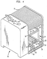
- the equipment skid 1 is illustrated as being covered by an enclosure 60.
- An enclosure 60 is provided with a vent opening 62 for connection to a system vent. Additionally, openings 64 and 68 are provided for piping to connect with the forelines 50, 52, and 53, and the exhaust lines 54, 56, and 58, respectively. Other openings, not shown in the particular view of Figure 4, are provided for facility connections. Access may be provided with a removable roll-type enclosure 70. Although not illustrated, a sensor can be provided within the enclosure 60 to detect the leakage.
- a common control unit could be provided for the vacuum pump and booster combinations 10 and 12 which could also advantageously be set in the service section 18.
- the external controls for operation of such a control unit could be placed on the enclosure 60.
Landscapes
- Container, Conveyance, Adherence, Positioning, Of Wafer (AREA)
- Valves And Accessory Devices For Braking Systems (AREA)
- Handcart (AREA)
- Compressors, Vaccum Pumps And Other Relevant Systems (AREA)
- Furnace Charging Or Discharging (AREA)
- Braking Arrangements (AREA)
- Centrifugal Separators (AREA)
- Multiple-Way Valves (AREA)
Abstract
Description
- This invention relates to an equipment skid to mount ancillary equipment which functions in connection with a semiconductor processing tool. More particularly, the present invention relates to such an equipment skid in which a plurality of equipment sections, used for mounting the ancillary equipment, are connected to a service section so that connections from the ancillary equipment can pass near or through the service section to the semiconductor processing tool.
- A semiconductor processing facility is often constructed on two levels. The tools used in fabricating the semiconductors will then be situated on a main level while ancillary equipment will be located on a level beneath the main level known as a sub-fab. Each piece of ancillary equipment situated within the sub-fab will ideally be beneath the tool it services. For instance, many tools incorporate a vacuum chamber. A vacuum pump associated with a particular chamber will then be located beneath such chamber on the sub-fab level.
- The placement of the equipment relative to the tools would appear to use the shortest runs of piping, in practice, however, excessive networks of piping result which can make the layout and servicing of the equipment very difficult. Installation of the equipment is also problematical in that the equipment must not only be assembled within the fabrication facility, but also be tested within such facility. If any piece of equipment proves to be faulty, it and possibly other surrounding equipment must be removed and replaced. A still further problem is that often such tools utilise noxious, dangerous chemicals that are drawn off by, for instance, vacuum pumps for disposal by a variety of types of abatement systems. However, due to the positioning of such pumps within the sub-fab it is difficult to shroud the pumps and associated piping with an enclosure to contain and vent leakage.
- The present invention is concerned with the provision of a central mounting arrangement on a skid that overcomes many of the problems mentioned above.
- In accordance with the invention, there is provided an equipment skid for mounting ancillary equipment to support a semiconductor processing tool, the equipment skid comprising a plurality of equipment sections; and a service section; said ancillary equipment mounted within the equipment sections; the plurality of equipment and service sections connected to one another to allow external connections between the ancillary equipment and the semiconductor processing tool to pass within a region overlying a footprint of the service section.
- The skid of the invention therefore provides a central location for mounting the ancillary equipment. Additionally, since a service section is provided for the external connections to the tool, less piping generally need be used than if equipment were scattered in the sub-fab. In this regard, in laying piping to the sub-fab, the footprint of the overall skid can be chalked out on the floor as a guide with attention given only to the service section to allow for the routing of piping from the main level of the fab.
- A further point is that the equipment and service sections are preferably covered by an enclosure to contain leakage. A sensor can be located within the enclosure to detect leakage.
- Preferably, the equipment and service sections are connected in an in-line relationship and also can have the same transverse cross-section. This facilitates the use of manifolds and the like to further reduce the amount of piping. For instance, when at least some of the ancillary equipment comprises vacuum pumps, at least one common manifold connects the vacuum pumps and extends in to the service section with fittings configured to connect with at least one conduit connected to the semiconductor processing tool. Utility manifolds may also be provided for cooling water or other services. Such utility manifolds are connected to the vacuum pumps and extend in to the service section for external utility connection.
- As may be appreciated, the use of the equipment skid of the present invention that is built up from sections facilitates the assembly of equipment off-site so that faulty equipment can be replaced before installation in the facility. In this regard, preferably, the equipment and service sections are connected to one another by connection elements that allow for assembly and disassembly of the equipment skid. In a further aspect of the present invention, the ancillary equipment can be mounted within the equipment sections on transversely extending members of tubular configuration to receive the tines of a fork lift vehicle to facilitate installation, removal and maintenance.
- For a better understanding of the invention and to show how the same may be put in to effect, reference will now be made, by way of exemplification only, to the accompanying drawings, in which:
- Figure 1 is a perspective view of an equipment skid in accordance with the invention;
- Figure 2 is a top plan view of Figure 1;
- Figure 3 is a side elevational view of Figure 1; and
- Figure 4 a perspective view of an enclosure used to contain an equipment skid in accordance with the invention with portions broken away and with only some components of the equipment skid illustrated.
-
- With reference to Figure 1, an equipment skid 1 in accordance with the invention is illustrated as
mounting vacuum pumps 10 and associatedbooster pumps 12. In the illustrated embodiment, theequipment skid 1 is provided withequipment sections vacuum pumps 10 and thebooster pumps 12 and aservice section 18 as a central point for the connection of thevacuum pumps 10 and thebooster pumps 12 to a semiconductor processing tool and to utilities such as house water. - With additional reference to Figures 2 and 3, each of the
equipment sections service section 18 is provided with parallel pairs of lowerlengthwise members 20 and 22 (See Figure 4) connected totransverse base members 24 to support equipment and theservice sections transverse base members 24 are provided withfeet 26. Four upright pairs ofmembers transverse base members 24. Upper pairs oflengthwise members transverse members upright members members equipment sections booster pump pairs members lengthwise members members - The equipment and
service sections service sections booster pump pairs equipment sections service sections service sections upright members connectors 44. - Once on site, in the event that maintenance were required for the vacuum and
booster pump pairs members relevant equipment section members booster pumps transverse base members 24 extend outwardly to allow for access to any equipment mounted on the equipment skid 1 - Each of the equipment and
service sections equipment sections service section 18. In this regard, the footprint of theservice section 18 as used herein and in the claims means the area bounded by thefeet 26 associated with thetransverse base members 24 thereof. This provides a central location for such connection to avoid networks of piping within the sub-fab. - Furthermore, the equipment and
service sections manifold 46 that serves as in inlet incorporates awater filter 49. Manifolds 46 and 48 terminate at theservice section 18 for connection to the appropriate utilities.Pump forelines forelines Exhaust lines service section 18 for connection to an abatement system. Supports for such piping could be connected to theservice section 18. Although not shown, in order to facilitate the separation of the equipment andservice sections manifolds forelines exhaust lines booster pump pairs service sections booster pump pairs - With additional reference to Figure 4, the
equipment skid 1 is illustrated as being covered by anenclosure 60. As stated previously, the advantage of such an arrangement is to contain all leakage from ancillary equipment mounted on the equipment skid 1 as well as from associated piping. Anenclosure 60 is provided with a vent opening 62 for connection to a system vent. Additionally,openings forelines exhaust lines type enclosure 70. Although not illustrated, a sensor can be provided within theenclosure 60 to detect the leakage. - Additionally, although not illustrated, a common control unit could be provided for the vacuum pump and
booster combinations service section 18. The external controls for operation of such a control unit could be placed on theenclosure 60.
Claims (7)
- An equipment skid for mounting ancillary equipment to support a semiconductor processing tool, the equipment skid comprising:a plurality of equipment sections; anda service section;said ancillary equipment mounted within the equipment sections;the plurality of equipment and service sections connected to one another to allow external connections between the ancillary equipment and the semiconductor processing tool to pass within a region overlying a footprint of the service section.
- An equipment skip according to Claim 1 in which the equipment and service sections are connected to one another in an in line relationship.
- An equipment skip according to Claim 1 or Claim 2 in which the equipment and service sections are covered by an enclosure to contain leakage.
- An equipment skid according to any preceding claim in which the equipment and service sections have the same transverse cross-section.
- An equipment skid according to any preceding claim in which the ancillary equipment is mounted within the equipment sections on transversely extending members of tubular configuration to receive the tines of a fork lift vehicle.
- An equipment skid according to any preceding claim in which:at least some of the ancillary equipment comprises vacuum pumps;at least one common manifold connects the vacuum pumps and extends in to the service section with fittings configured to connect with at least one conduit connected to the semiconductor processing tool;and utility manifolds for cooling water connect the vacuum pump and extend in to the service section for external utility connection.
- An equipment skid according to any preceding claim in which the equipment and service sections are connected to one another by connection elements that allow for assembly and disassembly of the equipment skid.
Applications Claiming Priority (2)
| Application Number | Priority Date | Filing Date | Title |
|---|---|---|---|
| US09/464,184 US6397883B1 (en) | 1999-12-16 | 1999-12-16 | Equipment skid |
| US464184 | 1999-12-16 |
Publications (3)
| Publication Number | Publication Date |
|---|---|
| EP1109204A2 true EP1109204A2 (en) | 2001-06-20 |
| EP1109204A3 EP1109204A3 (en) | 2005-11-16 |
| EP1109204B1 EP1109204B1 (en) | 2012-02-08 |
Family
ID=23842888
Family Applications (1)
| Application Number | Title | Priority Date | Filing Date |
|---|---|---|---|
| EP20000311168 Expired - Lifetime EP1109204B1 (en) | 1999-12-16 | 2000-12-14 | Compact equipment |
Country Status (7)
| Country | Link |
|---|---|
| US (1) | US6397883B1 (en) |
| EP (1) | EP1109204B1 (en) |
| JP (1) | JP4987186B2 (en) |
| KR (1) | KR100379145B1 (en) |
| AT (1) | ATE545149T1 (en) |
| SG (1) | SG89362A1 (en) |
| TW (1) | TW466566B (en) |
Cited By (3)
| Publication number | Priority date | Publication date | Assignee | Title |
|---|---|---|---|---|
| US7392825B2 (en) * | 2005-07-15 | 2008-07-01 | Edwards Vaccum, Inc. | Arrangement for tool equipment |
| CN108679310A (en) * | 2018-06-26 | 2018-10-19 | 湖北郢都水利水电建设有限公司 | A kind of pumping plant water outlet steel tube track holder device of rapid construction |
| WO2019092427A1 (en) * | 2017-11-13 | 2019-05-16 | Edwards Limited | Vacuum pumping and/or abatement system |
Families Citing this family (9)
| Publication number | Priority date | Publication date | Assignee | Title |
|---|---|---|---|---|
| US7077159B1 (en) * | 1998-12-23 | 2006-07-18 | Applied Materials, Inc. | Processing apparatus having integrated pumping system |
| US20070020115A1 (en) * | 2005-07-01 | 2007-01-25 | The Boc Group, Inc. | Integrated pump apparatus for semiconductor processing |
| US7441986B2 (en) * | 2006-01-30 | 2008-10-28 | Vince Rottinghaus | Ground heating device |
| US20070187521A1 (en) * | 2006-02-15 | 2007-08-16 | Wawak Ryszard J | Modular heat distribution unit for hydronic heating systems |
| JP2008172160A (en) * | 2007-01-15 | 2008-07-24 | Dainippon Screen Mfg Co Ltd | Substrate processing apparatus and substrate processing method |
| US9075408B2 (en) * | 2009-11-16 | 2015-07-07 | Applied Materials, Inc. | Energy savings and global gas emissions monitoring and display |
| RU121904U1 (en) * | 2012-06-18 | 2012-11-10 | Рационал Энерги Зюстеме Гмбх | BOILER EQUIPMENT SYSTEM, AND ALSO COMPONENT AND CONSTRUCTION ELEMENTS OF SUCH SYSTEM |
| US9207270B2 (en) * | 2012-08-31 | 2015-12-08 | Elwha Llc | Method and apparatus for measuring negawatt usage of an appliance |
| US10072673B2 (en) * | 2014-08-04 | 2018-09-11 | Powerex-Iwata Air Technology, Inc. | Compressor system |
Citations (2)
| Publication number | Priority date | Publication date | Assignee | Title |
|---|---|---|---|---|
| WO1999003133A1 (en) | 1997-07-11 | 1999-01-21 | Applied Materials, Inc. | Modular architecture for semiconductor wafer fabrication equipment |
| JPH11150057A (en) | 1997-11-19 | 1999-06-02 | Dainippon Screen Mfg Co Ltd | Substrate processing equipment |
Family Cites Families (8)
| Publication number | Priority date | Publication date | Assignee | Title |
|---|---|---|---|---|
| US4091840A (en) * | 1976-06-11 | 1978-05-30 | Daniel Valve Company | Flow distributing system |
| US4989632A (en) * | 1989-11-15 | 1991-02-05 | Bahm, Inc. | Apparatus for use in an automated liquid combination and transport system |
| JP2922440B2 (en) * | 1994-02-21 | 1999-07-26 | 松下電器産業株式会社 | How to open pneumatic equipment to atmosphere |
| JPH1097962A (en) * | 1996-09-19 | 1998-04-14 | Tokyo Electron Ltd | Processing device and processing system |
| US6083321A (en) * | 1997-07-11 | 2000-07-04 | Applied Materials, Inc. | Fluid delivery system and method |
| US5915414A (en) * | 1997-09-04 | 1999-06-29 | Lsi Logic Corporation | Standardized gas isolation box (GIB) installation |
| US6102068A (en) * | 1997-09-23 | 2000-08-15 | Hewlett-Packard Company | Selector valve assembly |
| TW484170B (en) * | 1999-11-30 | 2002-04-21 | Applied Materials Inc | Integrated modular processing platform |
-
1999
- 1999-12-16 US US09/464,184 patent/US6397883B1/en not_active Expired - Lifetime
-
2000
- 2000-12-07 TW TW89126089A patent/TW466566B/en not_active IP Right Cessation
- 2000-12-07 SG SG200007271A patent/SG89362A1/en unknown
- 2000-12-13 KR KR10-2000-0075999A patent/KR100379145B1/en not_active Expired - Lifetime
- 2000-12-14 JP JP2000379906A patent/JP4987186B2/en not_active Expired - Lifetime
- 2000-12-14 EP EP20000311168 patent/EP1109204B1/en not_active Expired - Lifetime
- 2000-12-14 AT AT00311168T patent/ATE545149T1/en active
Patent Citations (2)
| Publication number | Priority date | Publication date | Assignee | Title |
|---|---|---|---|---|
| WO1999003133A1 (en) | 1997-07-11 | 1999-01-21 | Applied Materials, Inc. | Modular architecture for semiconductor wafer fabrication equipment |
| JPH11150057A (en) | 1997-11-19 | 1999-06-02 | Dainippon Screen Mfg Co Ltd | Substrate processing equipment |
Cited By (9)
| Publication number | Priority date | Publication date | Assignee | Title |
|---|---|---|---|---|
| US7392825B2 (en) * | 2005-07-15 | 2008-07-01 | Edwards Vaccum, Inc. | Arrangement for tool equipment |
| EP1904776A4 (en) * | 2005-07-15 | 2010-06-02 | Edwards Vacuum Inc | ARRANGEMENT OF TOOL EQUIPMENT |
| WO2019092427A1 (en) * | 2017-11-13 | 2019-05-16 | Edwards Limited | Vacuum pumping and/or abatement system |
| WO2019092429A1 (en) * | 2017-11-13 | 2019-05-16 | Edwards Limited | A module for a vacuum pumping and/or abatement system |
| WO2019092408A1 (en) * | 2017-11-13 | 2019-05-16 | Edwards Limited | Vacuum pumping and/or abatement system |
| CN111356839A (en) * | 2017-11-13 | 2020-06-30 | 爱德华兹有限公司 | Module for a vacuum pumping and/or abatement system |
| US11512688B2 (en) | 2017-11-13 | 2022-11-29 | Edwards Limited | Module for a vacuum pumping and/or abatement system |
| TWI793210B (en) * | 2017-11-13 | 2023-02-21 | 英商愛德華有限公司 | A module for a vacuum pumping and/or abatement system |
| CN108679310A (en) * | 2018-06-26 | 2018-10-19 | 湖北郢都水利水电建设有限公司 | A kind of pumping plant water outlet steel tube track holder device of rapid construction |
Also Published As
| Publication number | Publication date |
|---|---|
| EP1109204B1 (en) | 2012-02-08 |
| EP1109204A3 (en) | 2005-11-16 |
| SG89362A1 (en) | 2002-06-18 |
| US6397883B1 (en) | 2002-06-04 |
| JP2001244160A (en) | 2001-09-07 |
| KR100379145B1 (en) | 2003-04-08 |
| KR20010062392A (en) | 2001-07-07 |
| TW466566B (en) | 2001-12-01 |
| ATE545149T1 (en) | 2012-02-15 |
| JP4987186B2 (en) | 2012-07-25 |
Similar Documents
| Publication | Publication Date | Title |
|---|---|---|
| US6397883B1 (en) | Equipment skid | |
| US7032614B2 (en) | Facilities connection box for pre-facilitation of wafer fabrication equipment | |
| EP3368729B1 (en) | A shaft pipe collection module | |
| US7063301B2 (en) | Facilities connection bucket for pre-facilitation of wafer fabrication equipment | |
| US8035029B2 (en) | Environmentally-isolated electrical junction box and method of installing and servicing the same | |
| US7806346B2 (en) | Cascade unit for a heating system with two or more heating boilers | |
| US20030116207A1 (en) | Apparatus for conveying fluids and base plate | |
| US20020069610A1 (en) | Installation docking pedestal for pre-facilitation of wafer fabrication equipment | |
| US20070082588A1 (en) | Methods and apparatus for coupling semiconductor device manufacturing equipment to the facilities of a manufacturing location | |
| KR101317997B1 (en) | Arrangement for tool equipment | |
| US20020162938A1 (en) | Facilities connection bucket for pre-facilitation of wafer fabrication equipment | |
| CN100450652C (en) | Platforms for industrial plants, especially for high-pressure descaling plants in rolling lines, emergency shears and oscillating flying shears, or similar | |
| KR102732987B1 (en) | Chemical Supply Unit and Central Chemical Supply System Including the Same | |
| CN110912422A (en) | A converter valve assembly and a frame-type valve tower having the same | |
| CN217449657U (en) | Automatic ultrafiltration device | |
| CN116197201B (en) | An integrated waste gas and waste liquid collection and discharge system for production sites | |
| US20030207664A1 (en) | Device for integrating a vacuum pumping system in a clean room false floor of a semiconductor component manufacturing plant | |
| CN204767764U (en) | Filter sledge is in block to be put | |
| JP3398913B2 (en) | Blowdown line of desulfurization equipment | |
| KR100615135B1 (en) | Fixing means for guide vanes for oil removal filter | |
| JPH08312307A (en) | Lubrication equipment installation method | |
| JPH0567665U (en) | Aquarium pump unit | |
| JPH1144290A (en) | Drain piping for air compressor |
Legal Events
| Date | Code | Title | Description |
|---|---|---|---|
| PUAI | Public reference made under article 153(3) epc to a published international application that has entered the european phase |
Free format text: ORIGINAL CODE: 0009012 |
|
| AK | Designated contracting states |
Kind code of ref document: A2 Designated state(s): AT BE CH CY DE DK ES FI FR GB GR IE IT LI LU MC NL PT SE TR |
|
| AX | Request for extension of the european patent |
Free format text: AL;LT;LV;MK;RO;SI |
|
| PUAL | Search report despatched |
Free format text: ORIGINAL CODE: 0009013 |
|
| AK | Designated contracting states |
Kind code of ref document: A3 Designated state(s): AT BE CH CY DE DK ES FI FR GB GR IE IT LI LU MC NL PT SE TR |
|
| AX | Request for extension of the european patent |
Extension state: AL LT LV MK RO SI |
|
| 17P | Request for examination filed |
Effective date: 20060411 |
|
| AKX | Designation fees paid |
Designated state(s): AT BE CH CY DE DK ES FI FR GB GR IE IT LI LU MC NL PT SE TR |
|
| 17Q | First examination report despatched |
Effective date: 20060727 |
|
| RAP1 | Party data changed (applicant data changed or rights of an application transferred) |
Owner name: BOC EDWARDS, INC. |
|
| RAP1 | Party data changed (applicant data changed or rights of an application transferred) |
Owner name: EDWARDS VACUUM, INC. |
|
| RAP1 | Party data changed (applicant data changed or rights of an application transferred) |
Owner name: EDWARDS VACUUM, INC. |
|
| GRAP | Despatch of communication of intention to grant a patent |
Free format text: ORIGINAL CODE: EPIDOSNIGR1 |
|
| GRAS | Grant fee paid |
Free format text: ORIGINAL CODE: EPIDOSNIGR3 |
|
| GRAA | (expected) grant |
Free format text: ORIGINAL CODE: 0009210 |
|
| AK | Designated contracting states |
Kind code of ref document: B1 Designated state(s): AT BE CH CY DE DK ES FI FR GB GR IE IT LI LU MC NL PT SE TR |
|
| REG | Reference to a national code |
Ref country code: GB Ref legal event code: FG4D |
|
| REG | Reference to a national code |
Ref country code: AT Ref legal event code: REF Ref document number: 545149 Country of ref document: AT Kind code of ref document: T Effective date: 20120215 Ref country code: CH Ref legal event code: EP |
|
| REG | Reference to a national code |
Ref country code: DE Ref legal event code: R082 Ref document number: 60046908 Country of ref document: DE Representative=s name: FLEUCHAUS & GALLO PARTNERSCHAFT, DE Ref country code: DE Ref legal event code: R082 Ref document number: 60046908 Country of ref document: DE Representative=s name: FLEUCHAUS & GALLO PARTNERSCHAFT MBB, DE |
|
| REG | Reference to a national code |
Ref country code: DE Ref legal event code: R096 Ref document number: 60046908 Country of ref document: DE Effective date: 20120405 |
|
| REG | Reference to a national code |
Ref country code: NL Ref legal event code: VDEP Effective date: 20120208 |
|
| PG25 | Lapsed in a contracting state [announced via postgrant information from national office to epo] |
Ref country code: NL Free format text: LAPSE BECAUSE OF FAILURE TO SUBMIT A TRANSLATION OF THE DESCRIPTION OR TO PAY THE FEE WITHIN THE PRESCRIBED TIME-LIMIT Effective date: 20120208 |
|
| PG25 | Lapsed in a contracting state [announced via postgrant information from national office to epo] |
Ref country code: FI Free format text: LAPSE BECAUSE OF FAILURE TO SUBMIT A TRANSLATION OF THE DESCRIPTION OR TO PAY THE FEE WITHIN THE PRESCRIBED TIME-LIMIT Effective date: 20120208 Ref country code: GR Free format text: LAPSE BECAUSE OF FAILURE TO SUBMIT A TRANSLATION OF THE DESCRIPTION OR TO PAY THE FEE WITHIN THE PRESCRIBED TIME-LIMIT Effective date: 20120509 Ref country code: PT Free format text: LAPSE BECAUSE OF FAILURE TO SUBMIT A TRANSLATION OF THE DESCRIPTION OR TO PAY THE FEE WITHIN THE PRESCRIBED TIME-LIMIT Effective date: 20120608 Ref country code: BE Free format text: LAPSE BECAUSE OF FAILURE TO SUBMIT A TRANSLATION OF THE DESCRIPTION OR TO PAY THE FEE WITHIN THE PRESCRIBED TIME-LIMIT Effective date: 20120208 |
|
| REG | Reference to a national code |
Ref country code: AT Ref legal event code: MK05 Ref document number: 545149 Country of ref document: AT Kind code of ref document: T Effective date: 20120208 |
|
| PG25 | Lapsed in a contracting state [announced via postgrant information from national office to epo] |
Ref country code: CY Free format text: LAPSE BECAUSE OF FAILURE TO SUBMIT A TRANSLATION OF THE DESCRIPTION OR TO PAY THE FEE WITHIN THE PRESCRIBED TIME-LIMIT Effective date: 20120208 |
|
| PG25 | Lapsed in a contracting state [announced via postgrant information from national office to epo] |
Ref country code: DK Free format text: LAPSE BECAUSE OF FAILURE TO SUBMIT A TRANSLATION OF THE DESCRIPTION OR TO PAY THE FEE WITHIN THE PRESCRIBED TIME-LIMIT Effective date: 20120208 Ref country code: SE Free format text: LAPSE BECAUSE OF FAILURE TO SUBMIT A TRANSLATION OF THE DESCRIPTION OR TO PAY THE FEE WITHIN THE PRESCRIBED TIME-LIMIT Effective date: 20120208 |
|
| PG25 | Lapsed in a contracting state [announced via postgrant information from national office to epo] |
Ref country code: IT Free format text: LAPSE BECAUSE OF FAILURE TO SUBMIT A TRANSLATION OF THE DESCRIPTION OR TO PAY THE FEE WITHIN THE PRESCRIBED TIME-LIMIT Effective date: 20120208 |
|
| PLBE | No opposition filed within time limit |
Free format text: ORIGINAL CODE: 0009261 |
|
| STAA | Information on the status of an ep patent application or granted ep patent |
Free format text: STATUS: NO OPPOSITION FILED WITHIN TIME LIMIT |
|
| 26N | No opposition filed |
Effective date: 20121109 |
|
| PG25 | Lapsed in a contracting state [announced via postgrant information from national office to epo] |
Ref country code: AT Free format text: LAPSE BECAUSE OF FAILURE TO SUBMIT A TRANSLATION OF THE DESCRIPTION OR TO PAY THE FEE WITHIN THE PRESCRIBED TIME-LIMIT Effective date: 20120208 |
|
| REG | Reference to a national code |
Ref country code: DE Ref legal event code: R097 Ref document number: 60046908 Country of ref document: DE Effective date: 20121109 |
|
| PG25 | Lapsed in a contracting state [announced via postgrant information from national office to epo] |
Ref country code: ES Free format text: LAPSE BECAUSE OF FAILURE TO SUBMIT A TRANSLATION OF THE DESCRIPTION OR TO PAY THE FEE WITHIN THE PRESCRIBED TIME-LIMIT Effective date: 20120519 |
|
| PG25 | Lapsed in a contracting state [announced via postgrant information from national office to epo] |
Ref country code: MC Free format text: LAPSE BECAUSE OF NON-PAYMENT OF DUE FEES Effective date: 20121231 |
|
| REG | Reference to a national code |
Ref country code: CH Ref legal event code: PL |
|
| REG | Reference to a national code |
Ref country code: IE Ref legal event code: MM4A |
|
| PG25 | Lapsed in a contracting state [announced via postgrant information from national office to epo] |
Ref country code: LI Free format text: LAPSE BECAUSE OF NON-PAYMENT OF DUE FEES Effective date: 20121231 Ref country code: IE Free format text: LAPSE BECAUSE OF NON-PAYMENT OF DUE FEES Effective date: 20121214 Ref country code: CH Free format text: LAPSE BECAUSE OF NON-PAYMENT OF DUE FEES Effective date: 20121231 |
|
| PG25 | Lapsed in a contracting state [announced via postgrant information from national office to epo] |
Ref country code: TR Free format text: LAPSE BECAUSE OF FAILURE TO SUBMIT A TRANSLATION OF THE DESCRIPTION OR TO PAY THE FEE WITHIN THE PRESCRIBED TIME-LIMIT Effective date: 20120208 |
|
| PG25 | Lapsed in a contracting state [announced via postgrant information from national office to epo] |
Ref country code: LU Free format text: LAPSE BECAUSE OF NON-PAYMENT OF DUE FEES Effective date: 20121214 |
|
| REG | Reference to a national code |
Ref country code: FR Ref legal event code: CJ Effective date: 20150225 Ref country code: FR Ref legal event code: CA Effective date: 20150225 Ref country code: FR Ref legal event code: CD Owner name: EDWARDS VACUUM, LLC, US Effective date: 20150225 |
|
| REG | Reference to a national code |
Ref country code: DE Ref legal event code: R082 Ref document number: 60046908 Country of ref document: DE Representative=s name: FLEUCHAUS & GALLO PARTNERSCHAFT MBB, DE |
|
| REG | Reference to a national code |
Ref country code: DE Ref legal event code: R082 Ref document number: 60046908 Country of ref document: DE Representative=s name: FLEUCHAUS & GALLO PARTNERSCHAFT MBB, DE Effective date: 20150415 Ref country code: DE Ref legal event code: R081 Ref document number: 60046908 Country of ref document: DE Owner name: EDWARDS VACUUM LLC (N.D. GES. D. STAATES DELAW, US Free format text: FORMER OWNER: EDWARDS VACUUM, INC., TEWKSBURY, MASS., US Effective date: 20150415 Ref country code: DE Ref legal event code: R082 Ref document number: 60046908 Country of ref document: DE Representative=s name: FLEUCHAUS & GALLO PARTNERSCHAFT MBB, DE Effective date: 20120322 Ref country code: DE Ref legal event code: R081 Ref document number: 60046908 Country of ref document: DE Owner name: EDWARDS VACUUM LLC (N.D. GES. D. STAATES DELAW, US Free format text: FORMER OWNER: THE BOC GROUP, INC., MURRAY HILL, N.J., US Effective date: 20120213 |
|
| REG | Reference to a national code |
Ref country code: FR Ref legal event code: PLFP Year of fee payment: 16 |
|
| REG | Reference to a national code |
Ref country code: FR Ref legal event code: PLFP Year of fee payment: 17 |
|
| REG | Reference to a national code |
Ref country code: FR Ref legal event code: PLFP Year of fee payment: 18 |
|
| PGFP | Annual fee paid to national office [announced via postgrant information from national office to epo] |
Ref country code: FR Payment date: 20191226 Year of fee payment: 20 |
|
| PGFP | Annual fee paid to national office [announced via postgrant information from national office to epo] |
Ref country code: DE Payment date: 20191231 Year of fee payment: 20 Ref country code: GB Payment date: 20200102 Year of fee payment: 20 |
|
| REG | Reference to a national code |
Ref country code: DE Ref legal event code: R071 Ref document number: 60046908 Country of ref document: DE |
|
| REG | Reference to a national code |
Ref country code: GB Ref legal event code: PE20 Expiry date: 20201213 |
|
| PG25 | Lapsed in a contracting state [announced via postgrant information from national office to epo] |
Ref country code: GB Free format text: LAPSE BECAUSE OF EXPIRATION OF PROTECTION Effective date: 20201213 |