EP1109037A2 - Spleissgehäuse mit austauschbaren und kippbaren Spleissstapeln und zugehörige Verfahren - Google Patents
Spleissgehäuse mit austauschbaren und kippbaren Spleissstapeln und zugehörige Verfahren Download PDFInfo
- Publication number
- EP1109037A2 EP1109037A2 EP00127543A EP00127543A EP1109037A2 EP 1109037 A2 EP1109037 A2 EP 1109037A2 EP 00127543 A EP00127543 A EP 00127543A EP 00127543 A EP00127543 A EP 00127543A EP 1109037 A2 EP1109037 A2 EP 1109037A2
- Authority
- EP
- European Patent Office
- Prior art keywords
- splice
- support frame
- pivot
- trays
- splice tray
- Prior art date
- Legal status (The legal status is an assumption and is not a legal conclusion. Google has not performed a legal analysis and makes no representation as to the accuracy of the status listed.)
- Withdrawn
Links
Images





Classifications
-
- G—PHYSICS
- G02—OPTICS
- G02B—OPTICAL ELEMENTS, SYSTEMS OR APPARATUS
- G02B6/00—Light guides; Structural details of arrangements comprising light guides and other optical elements, e.g. couplings
- G02B6/44—Mechanical structures for providing tensile strength and external protection for fibres, e.g. optical transmission cables
- G02B6/4439—Auxiliary devices
- G02B6/444—Systems or boxes with surplus lengths
- G02B6/4441—Boxes
- G02B6/4442—Cap coupling boxes
-
- G—PHYSICS
- G02—OPTICS
- G02B—OPTICAL ELEMENTS, SYSTEMS OR APPARATUS
- G02B6/00—Light guides; Structural details of arrangements comprising light guides and other optical elements, e.g. couplings
- G02B6/44—Mechanical structures for providing tensile strength and external protection for fibres, e.g. optical transmission cables
- G02B6/4439—Auxiliary devices
- G02B6/444—Systems or boxes with surplus lengths
- G02B6/4453—Cassettes
- G02B6/4454—Cassettes with splices
Definitions
- the present invention relates generally to optical fiber interconnection closures and, more particularly, to splice closures with removable and pivotable splice trays.
- Fiber optic networks typically include interconnection closures at various splice locations throughout the fiber optic network.
- these interconnection closures include splice closures and patch closures.
- splice closures commonly house the splices connecting the optical fibers of one or more distribution cables to respective ones of the optical fibers of a fiber optic feeder cable.
- a splice closure protects the spliced end portions of the optical fibers from environmental degradation, strain, and other deleterious forces, thereby increasing the reliability and quality of the splices.
- a typical butt-type splice closure includes a housing open at one end and a single end cap positioned within the open end of the housing. Each of the fiber optic cables associated with the butt-type splice closure extends through the single end cap.
- a typical in-line splice closure includes a housing open at both of its opposite ends and a pair of end caps respectively positioned within the open ends of the housing so fiber optic cables can enter the in-line splice closure from either end of the housing.
- Conventional splice closures of the above-described types generally include a frame that is connected to the end cap(s) and carries a number of splice trays that are disposed in a stacked arrangement within the housing.
- Each splice tray includes one or more splice organizers for receiving the spliced end portions of optical fibers.
- a splice closure contains multiple splice trays that can be individually pivoted and accessed.
- the splice closure has a housing defining an internal cavity and at least one opening to the internal cavity.
- An end cap is capable of occluding the opening of the housing to provide an enclosed configuration.
- a support frame has opposite front and rear ends, and the front end of the support frame is connected to the end cap so that the support frame is capable of being positioned within the internal cavity of the housing during the enclosed configuration.
- the support frame extends in a longitudinal direction between the front and rear ends, and defines a frame axis that extends in the longitudinal direction.
- Multiple splice trays that are capable of supporting optical fiber splices are carried by the support frame.
- Each splice tray is mounted to be capable of pivoting relative to the support frame. More specifically, there are a plurality of axes of rotation that are generally parallel to the frame axis and about which the splice trays are respectively pivotable.
- a front end of the splice tray is carried by a front pivot that is carried by the support frame, and a rear end of the splice tray is carried by a rear pivot that is carried by the support frame.
- a biasing mechanism is operative to hold the splice tray to the support frame.
- the splice tray can be removed from the support frame by manually overcoming the force exerted by the biasing mechanism.
- the splice tray can be installed to the support frame by manually overcoming the force exerted by the biasing mechanism.
- the biasing mechanism can be part of an active pivot, one or more components of a fiber optic cable, such as buffer tubes, or the like.
- pivots that are pivotally carrying adjacent splice trays are arranged so external surfaces of adjacent splice trays cooperate to define a cascade-like configuration.
- the cascade-like configuration at least partially facilitates the individual pivoting of at least some of the splice trays.
- restricting mechanisms are provided for limiting the pivoting of the splice trays pivotally carried by the support frame.
- a first group of the splice trays is spaced apart from a second group of the slice trays in a lateral direction so a space is defined between the first and second groups of splice trays.
- the space between the groups of splice trays is capable of receiving and storing excess portions of the buffer tubes.
- the splice closures of the present invention advantageously contain multiple splice trays that can be individually pivoted and accessed so that the splice closures are capable of optimally carrying and providing access to numerous optical fibers and optical fiber splices.
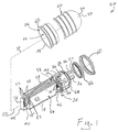
- Figure 1 is a partially schematic, generally rear, exploded pictorial view of a splice closure, in accordance with a first embodiment of the present invention.
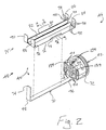
- Figure 2 is an isolated, generally rear, partially schematic, and partially exploded view of a support assembly of the closure of Figure 1.
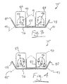
- Figure 3 is an isolated, partially schematic cross-sectional view of a carrier assembly of the support assembly of Figure 2, taken along line 3-3 of Figure 2.
- Figure 4 is an isolated, partially schematic cross-sectional view of the carrier assembly taken along line 4-4 of Figure 2.
- Figure 5 schematically illustrates a representative active pivot of the carrier assembly of Figure 2.
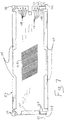
- Figure 6 is an isolated, partially schematic, front elevation view of a representative splice tray of the closure of Figure 1.
- Figure 7 is an isolated, partially schematic, plan view of a tray-like base of the splice tray of Figure 6.
- Figure 8 is an isolated, partially schematic, rear elevation view of the splice tray of Figure 6.
- Figure 9 is a schematic, rear elevation view of the support assembly and splice trays of Figure 1, with some of the splice trays in parallel configurations and other of the splice trays in non-parallel configurations, in accordance with the first embodiment of the present invention.
- Figure 10 is a partially schematic plan view of lower front and rear portions of a tray-like base of a splice tray, in accordance with a second embodiment of the present invention.
- Figure 11 is an isolated, partially schematic, rear elevation view of the splice tray of Figure 10.
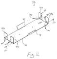
- Figure 12 is an isolated pictorial view of a carrier assembly with a pair of schematically illustrated pivots exploded therefrom, in accordance with a third embodiment of the present invention.
- Figure 13 is a partially schematic plan view of lower front and rear portions of a tray-like base of a splice tray, in accordance with a fourth embodiment of the present invention.
- Figure 14 is a schematic, left side elevation view of a support assembly and splice trays in parallel configurations, in accordance with a fifth embodiment of the present invention.
- Splice closures of the present invention advantageously contain multiple splice trays that can be individually pivoted and accessed so that the splice closures are capable of optimally carrying and providing access to numerous optical fibers and optical fiber splices.
- FIG. 1 illustrates an optical fiber interconnection closure in the form of a butt-type splice closure 20 .
- the closure 20 includes a housing 22 defining an internal cavity 24 and an opening 26 to the cavity. Whereas the housing 22 can have a variety of shapes, the illustrated housing has a generally cylindrical shape.
- the opening 26 is positioned at a front end 28 of the housing 22 , and the opposite rear end 30 of the housing is closed.
- the wall of the housing 22 extends around and defines a housing axis 32 extending between the front end 28 and the rear end 30 of the housing.
- the cavity 24 receives and the housing 22 carries a butt-type support assembly 34 .
- the support assembly 34 holds fiber optic cables 36 .
- Buffer tubes 38 containing optical fibers extend from the fiber optic cables 36 .
- the support assembly 34 supports the buffer tubes 38 , optical fibers, and splices (not shown) that connect the optical fibers.
- the buffer tubes 38 can contain individual optical fibers or optical fiber ribbons.
- the support assembly 34 includes an end cap 42 and a butt-type support frame 40 connected to and extending rearward from the end cap.
- the end cap 42 defines multiple ports 44 that extend through the end cap, from the front to the rear of the end cap, for respectively receiving fiber optic cables 36 ( Figure 1).
- Ports 44 that are not occupied by fiber optic cables 36 are occluded by removable caps (not shown) positioned at the front side of the end cap 44 .
- each of the ports 44 is in receipt of a respective fiber optic cable or a respective portion of a fiber optic cable.
- a respective hose clamp (not shown), or the like, to extend around the fiber optic cable and attach the fiber optic cable to a respective strain-relief bracket (not shown).
- the strain-relief brackets extend rearward from channels 139 ( Figure 2) defined by the rear side of the end cap 42 .
- the support frame 40 is carried by the end cap 42 in a cantilever-like fashion.
- the support assembly 34 is movable between an enclosed configuration and an unenclosed configuration.
- the end cap 42 is positioned in the opening 26 of the housing 22 during the enclosed configuration.
- the support frame 40 and the components carried thereby are positioned within the cavity 24 of the housing 22 during the enclosed configuration.
- the end cap 42 is removed from the opening 26 to provide the unenclosed configuration.
- the support frame 40 and the components carried thereby are removed from the cavity 24 during the unenclosed configuration.
- the support frame 40 has a front end 46 and an opposite rear end 48 .
- the support frame 40 extends in a longitudinal direction between the front and rear ends 46, 48, and the support frame defines a frame axis 50 extending in the longitudinal direction.
- the frame axis 50 is generally parallel to the housing axis 32 ( Figure 1) while the closure 20 ( Figure 1) is in the enclosed configuration.
- each splice tray 52 is a container-like device designed for containing portions of at least some of the optical fibers and at least some of the splices that connect the optical fibers.
- the splice trays 52 are pivotable about respective splice tray pivot axes 53 ( Figures 6-9) that are generally parallel to the frame axis 50 .
- the splice trays 52 are in parallel configurations in Figure 1. In contrast, some of the splice trays 52 are in non-parallel configurations in Figure 9.
- Each splice tray 52 respectively defines and extends in a longitudinal plane that extends in the longitudinal direction while the splice tray is pivotally carried by the support frame 40 in the manner described below. All of the longitudinal planes of the splice trays 52 are parallel while the splices trays are in their parallel configurations. In contrast, not all of the longitudinal planes are parallel while one or more of the splice trays 52 are in their non-parallel configuration.
- a right group 54 of the splice trays 52 is spaced apart from a left group 56 of the slice trays 52 in a lateral direction that is generally perpendicular to the longitudinal direction.
- a storage space 58 is defined between the right and left groups of splice trays 52 . Excess portions of buffer tubes 38 are coiled and placed in the storage space 58 .
- the illustrated closure 20 includes a split annular collar 60 that securely engages a circumferential flange 62 of the housing 22 and a circumferential flange 64 of the end cap 42 to secure the end cap to the housing.
- the collar 60 and circumferential flanges 62, 64 cooperate with an O-ring 66 that is received in a circumferential channel 68 defined by the end cap 42 .
- the cavity 24 of the housing 22 is substantially watertight while the closure 20 is in the enclosed configuration.
- the closure 20 illustrated in Figure 1 is a butt-type closure, the closures of the present invention can be in-line closures or other types of closures without departing from the scope of the present invention.
- the support frame 40 includes a support bar 70 having a front end connected proximate to a generally cylindrical peripheral or circumferential surface 72 of the end cap 42 by a threaded attachment device such as a bolt 73 (Figure 9), or the like.
- the rear end of the support bar 70 is in the form of an appendage 74 that extends perpendicularly with respect to the frame axis 50 ( Figure 1).
- the appendage 74 is generally a rear boundary to the storage space 58 ( Figure 1). That is, the appendage 74 functions to help retain the excess portions of the buffer tubes 38 (Figure 1) in the storage space 58 .
- the support frame 40 further includes a carrier assembly 75 that is exploded away from the support bar 70 in Figure 2.
- the carrier assembly 75 includes a base-like plate member 76 that is mounted to the support bar 70 by threaded attachment devices, welding, or the like.
- a left restricting flange 78 extends from a left longitudinal edge of the plate member 76 .
- a right restricting flange 80 extends from a right longitudinal edge of the plate member 76 .
- Each of the restricting flanges 78, 80 extend at an acute angle with respect to the broad upper surface of the plate member 76 .
- the restricting flanges 78, 80 function as stops for restricting the pivoting of the respective splice tray 52 ( Figure 1) most proximate thereto, as will be discussed in greater detail below.
- a U-shaped channel 82 extends between a front lateral edge of the plate member 76 and an opposite rear lateral edge of the plate member.
- the walls of the U-shaped channel 82 at least partially define a lower portion of the storage space 58 ( Figure 1).
- the longitudinally extending upper edges the walls of the U-shaped channel 82 that extend generally perpendicularly from the broad surface of the plate member 76 function as stops for restricting the pivoting of the respective splice tray 52 ( Figure 1) most proximate thereto, as will be discussed in greater detail below.
- the walls of the U-shaped channel 82 that extend generally perpendicularly from the broad surface of the plate member 76 function to restrict any buffer tubes 38 contained in the storage space 58 from becoming entangled in the space defined between the upper surface of the plate member 76 and the bottoms of the splice trays 52 ( Figure 1), which will be discussed in greater detail below.
- a series of passive pivots 92 are mounted to and carried by left and right front extensions 84, 86 .
- the front extensions 84, 86 respectively extend from left and right portions of the front lateral edge of the plate member 76 .
- the front extensions 84, 86 extend generally perpendicularly from the broad surface of the plate member 76 upon which the U-shaped channel 82 is mounted.
- the passive pivots 92 are preferably rods, pins, or the like.
- the passive pivots 92 carried by the left front extension 84 are arranged along a line 91
- the passive pivots carried by the right front extension 86 are arranged along a line 93 that defines an obtuse angle with respect to the line 91 .
- Each of the lines 91, 93 individually form an acute angle with respect to the surface of the plate member 76 that carries the U-shaped channel 82 .
- a respective restrictive receptacle 94 is positioned above each of the passive pivots 92 carried by the front extensions 84 , 86 .
- the restrictive receptacles 94 are preferably recesses or apertures defined by the front extensions 84, 86 .
- a series of active pivots 96 are respectively mounted to and carried by left and right rear extensions 88, 90 .
- the rear extensions 88, 90 respectively extend from left and right portions of the rear lateral edge of the plate member 76 .
- the rear extension 88, 90 extend generally perpendicularly from the broad surface of the plate member 76 upon which the U-shaped channel 82 is mounted.
- the active pivots 96 carried by the left rear extension 88 are arranged along a line 95
- the active pivots carried by the right rear extension 90 are arranged along a line 97 that defines an obtuse angle with respect to the line 95 .
- Each of the lines 95, 97 individually form an acute angle with respect to the surface of the plate member 76 that carries the U-shaped channel 82 .
- the described representative active pivot 96 is one of the group of active pivots mounted to and carried by the left rear extension 88 , a corresponding group of the active pivots is similarly mounted to and carried by the right rear extension 90 ( Figure 4).
- the representative active pivot 96 includes a telescoping assembly 98 , or the like, having one end mounted to and carried by the left rear extension 88 and an opposite end that carries a lobe 100 .
- the telescoping assembly 98 includes an inner rod or pin that extends into an axial cavity of an outer rod or pin, or the like, as illustrated by broken lines in Figure 5.
- the lobe 100 includes a broad camlike guiding surface 102 that tapers to a generally pointed terminus 104 .
- a biasing mechanism of the representative active pivot 96 is illustrated in the form a spring 105 .
- a middle portion of the spring 105 is cut away in Figure 5 in order to more clearly show the telescoping assembly 98 .
- the spring 105 has opposite ends that are respectively immovably mounted with respect to the left rear extension 88 and the lobe 100 .
- the spring 105 biases the lobe 100 away from the left rear extension 88 and also functions to hold the lobe so that the lobe does not become separated from its telescoping assembly 98 .
- the splice tray 52 includes a tray-like base 106 , a splice organizer 108 mounted to the tray-like base and defining a plurality of parallel grooves for respectively receiving optical fiber splices, and a removable cover 110 for generally closing the tray-like base to cover and protect the splices carried by the splice organizer. Closing and reopening of the splice tray 52 is facilitated by longitudinally extending and curved lips 112 of the cover 110 that snap over longitudinally extending and curved lips 114 of the tray-like base 106 .
- the tray-like base 106 includes tabs 116 at its opposite front and rear ends.
- the tabs 116 are designed for being crimped around buffer tubes 38 (Figure 1) that enter the splice tray 52 .
- the tray-like base 106 defines multiple apertures 118 , each of which is designed for receiving a conventional cable tie (not shown), or the like, that holds buffer tubes 38 entering the splice tray 52 .
- the tray-like base 106 includes a front wall 120 that partially occludes a front opening 122 to the interior of the splice tray 52 .
- the front wall 120 defines a front pivot receptacle 124 and a restrictive protrusion 126 .
- the restrictive protrusion 126 is preferably a bump, or the like, that extends forward from the front surface of the front wall 120 .
- the tray-like base 106 further includes a lower rear wall 128 and an upper rear wall 130 that together partially occlude a rear opening 132 to the interior of the splice tray 52 .
- the lower rear wall 128 defines a rear pivot receptacle 136 .
- Each of the pivot receptacles 124, 136 ( Figures 6 and 8) is preferably an aperture, or the like.
- the tray-like base 106 further includes supplemental walls 138 that respectively cooperate with the front wall 120 and the lower rear wall 128, and other walls of the splice tray 52, to define protective chambers.
- the protective chambers respectively receive the tips of the pivots 92, 96 that protrude into the pivot receptacles 124, 136 ( Figures 6 and 8).
- the protective chambers isolate and protect the buffer tubes 38 ( Figure 1) contained by the splice tray 52 from the tips of the pivots 92, 96 that pivotally carry the splice tray.
- the right-most splice tray 52 of the right group 54 of splice trays is pivotally carried by both the right-most passive pivot 92 carried by the right front extension 86 and the right-most active pivot 96 carried by the right rear extension 90 .
- the middle splice tray of the right group 54 is pivotally carried by both the middle passive pivot 92 carried by the right front extension 86 and the middle active pivot 96 carried by the right rear extension 90 .
- the left-most splice tray 52 of the right group 54 is pivotally carried by both the left-most passive pivot 92 carried by the right front extension 86 and the left-most active pivot 96 carried by the right rear extension 90 .
- the right-most splice tray 52 of the left group 56 of splice trays is pivotally carried by both the right-most passive pivot 92 carried by the left front extension 84 and the right-most active pivot 96 carried by the left rear extension 88 .
- the middle splice tray of the left group 56 is pivotally carried by both the middle passive pivot 92 carried by the left front extension 84 and the middle active pivot 96 carried by the left rear extension 88 .
- the left-most splice tray 52 of the left group 56 is pivotally carried by both the left-most passive pivot 92 carried by the left front extension 84 and the left-most active pivot 96 carried by the left rear extension 88 .
- the rear end of the splice tray 52 continues to be lowered so that the lower rear wall 128 continues to slidingly engage the guiding surface 102 and the spring 105 ( Figure 5) of the active pivot 96 is compressed.
- the rear end of the splice tray 52 is lowered so the terminus 104 ( Figures 4-5) of the lobe 100 becomes aligned with and received in the rear pivot receptacle 136 ( Figure 8).
- the splice tray 52 is released and the spring 105 of the active pivot 96 expands so that the lobe 100 forces the splice tray 52 forward.
- the passive pivot 92 remains within the front pivot receptacle 124 and the terminus 104 of the active pivot 96 remains in the rear pivot receptacle 136 .
- the pivot axis 53 of the splice tray 52 is coaxial with the pivots 92, 96 carrying the splice tray.
- the manual removal of a representative one of the splice trays 52 from the respective pivots 92, 96 pivotally carrying the splice tray 52 will now be described.
- the splice tray 52 is manually moved rearward to compress the spring 105 of the active pivot 96 until the passive pivot 92 no longer extends into the front pivot receptacle 124 . Thereafter, the front end of the splice tray 52 is tilted upward and the entire splice tray 52 is moved forward and upward so the terminus 104 of the active pivot 96 is withdrawn from the rear pivot receptacle 136 .
- splice trays 52 pivotally carried between respective pivots 92, 96 can be pivoted about their respective pivot axes 53 (Figures 6-9) between parallel configurations (illustrated in Figure 1) and non-parallel configurations (some of which are illustrated in Figure 9), while the closure 20 ( Figure 1) is in the unenclosed configuration.
- a splice tray 52 that is in its parallel configuration extends generally perpendicularly from the surface of the plate member 76 that carries the U-shaped channel 82 .
- the parallel configurations provide for compact packaging of the pivoting splice trays 52 .
- the non-parallel configurations provide optimal access to the splice trays 52 so that one or more of the splice trays can be readily individually removed from or installed to the carrier assembly 75 in the manners described above.
- the bottom sides of the splice trays 52 define a cascade-like configuration while in their parallel configurations.
- the cascade-like configuration is partially illustrated in broken lines in Figure 9 with respect to the two splice trays 52 of the left group 56 that are in their parallel configurations.
- the cascade-like configuration of the bottom sides of adjacent splice trays 52 allows a lower corner of a lower one of the adjacent pair of splice trays to be pivoted to a position that is directly beneath the lower end of the upper one of the adjacent pair of splice trays.
- This feature is illustrated in broken lines in Figure 9 with respect to the left-most pair of splice trays 52 of the left group 56 . This feature provides for the pivoting of the compactly packaged splice trays 52 .
- Pivoting of the splice trays 52 installed to the carrier assembly 75 is restricted by several different features.
- the restricting flanges 78, 80 ( Figures 2-4) function as stops for restricting the pivoting of the splice tray 52 most proximate thereto.
- the longitudinally extending upper edges of the walls of the U-shaped channel 82 ( Figures 2-4) that extend generally perpendicularly from the broad surface of the plate member 76 function as stops for restricting the pivoting of the splice trays 52 most proximate thereto.
- the interaction of a representative one of the splice trays 52 and the respective restrictive receptacle 94 ( Figures 2-3) associated therewith will now be described.
- the restrictive protrusion 126 ( Figures 6-7) cooperates with the restrictive receptacle 94 to releasably hold the splice tray 52 in its parallel configuration (for example, each of the splice trays is in its parallel configuration in Figure 1).
- the restricting interaction between the protrusion 126 and the receptacle 94 can be manually overcome so that the splice tray 52 can be pivoted to its non-parallel configuration (for example, a majority of the splice trays are in their non-parallel configuration in Figure 9).
- multiple additional restrictive receptacles 94 are defined in the rear surfaces of the front extensions 84, 86 ( Figures 2-3) for respectively removably receiving the restrictive protrusions 126 while the splice trays 52 are arranged in configurations other than the parallel configurations.
- a removable elongate fastener (not shown), such as a strap, is wrapped around the splice trays 52 and the carrier assembly 75 while all of the splice trays 52 are intended to remain in their parallel configurations, such as during the enclosed configuration.
- the ends of the strap preferably include pieces of attachment material, such as that sold under the trademark VELCRO, clasps, or other connecting mechanisms for allowing the strap to securely hold the splice trays 52 and excess portions of buffer tubes 38 ( Figure 1) to the carrier assembly 75 .
- the strap can also hold additional components (not shown) to the carrier assembly 75 , such as conventional container-like devices for containing optical fibers, including slack baskets and splice trays, or the like.
- each of the restrictive receptacles 94 of the front extensions 84 , 86 is replaced with a restrictive protrusion (for example see the restrictive protrusion 126 ), and each of the restrictive protrusions 126 of the splice trays 52 is replaced with a restrictive receptacle (for example see the restrictive receptacles 94 ).
- each of the front extensions 84 , 86 is absent of the restrictive receptacles 94 and the splice trays 52 are absent of the restrictive protrusions 126 .
- a closure of a second embodiment of the present invention is identical to the closure 20 (Figure 1) of the first embodiment of the present invention, except for variations noted and variations apparent to those of ordinary skill in the art in view of this disclosure.
- the splice trays carried by the carrier assembly 75 ( Figures 2-4) are different from the splice trays 52 ( Figures 1, 6, 8 and 9) of the first embodiment. More specifically, each of the splice trays of the second embodiment includes a tray-like base 106a (partially shown in Figure 10) rather than the tray-like base 106 ( Figures 6-8) of the first embodiment.
- the tray-like base 106a includes front and rear tabs 140, 142 that extend beyond the lower lip 114 of the tray-like base.
- Tabs 140, 142 defining the pivot receptacles 124a, 136a extend perpendicularly to the portion of the tray-like base 106a defining the apertures 118, as illustrated in Figure 10.
- the tabs 140, 142 are preferably reinforced, if necessary, to increase their rigidity.
- the front pivot receptacle 124a receives and is pivotally carried by a respective passive pivot 92 ( Figures 2 and 3)
- the rear pivot receptacle 136a receives and is pivotally carried by a respective active pivot 96 ( Figures 4 and 5)
- the restrictive protrusion 126a cooperates with a respective restrictive receptacle 94 ( Figures 2 and 3).
- a closure of a third embodiment of the present invention is identical to the closure 20 (Figure 1) of the first embodiment of the present invention, except for variations noted and variations apparent to those of ordinary skill in the art in view of this disclosure.
- a carrier assembly 75b ( Figure 11) is used in place of the carrier assembly 75 ( Figures 2-4) of the first embodiment.
- the carrier assembly 75b of the third embodiment is different from the carrier assembly 75 ( Figures 2-4) of the first embodiment because the carrier assembly 75b of the third embodiment does not include the restrictive receptacles 94 ( Figures 2-3), each of the passive pivots 92 ( Figures 2-3) is replaced with a front pivot receptacle 144 , and each of the active pivots 96 ( Figures 4-5) is replaced with a rear pivot receptacle 148 .
- Each of the pivot receptacles 144, 148 is preferably an aperture, or the like, respectively defined through one of the extensions 84b, 86b, 88b, 90b .
- the carrier assembly 75b includes a pair of restricting tabs 146 extending rearward from the front extensions 84b, 86b .
- the restricting tabs 146 function as stops for restricting the pivoting of the splice trays 52 ( Figures 1, 6, 8, and 9) most proximate thereto so that those splice trays do not pivot into the storage space 58 ( Figure 1) defined between the right and left groups 54, 56 ( Figure 1) of splice trays.
- a representative splice tray 52 ( Figures 1, 6, 8, and 9) to the carrier assembly 75b of the third embodiment will now be described with respect to representative pivot receptacles 144, a representative pivot receptacle 148 and representative pivots 150, 152 .
- the pivot receptacles 124, 136 ( Figures 6 and 8) of the splice tray 52 are respectively aligned with the pivot receptacles 144, 148 .
- a front pivot 150 that is initially separate from the splice tray 52 and the carrier assembly 75b is positioned through the aligned pivot receptacles 124, 144 so that the front pivot is carried by the carrier assembly and pivotally carries the splice tray.
- a rear pivot 152 that is initially separate from the splice tray 52 and the carrier assembly 75b is positioned through the aligned pivot receptacles 136, 148 so that the rear pivot is carried by the carrier assembly and pivotally carries the splice tray.
- the front and rear pivots 150, 152 are removed from the pivot receptacles 124, 136, 144, 148 to release the splice tray 52 from the carrier assembly 75b .
- the front and rear pivots 150, 152 are preferably each conventional threaded devices, such as screws or bolts, or the like.
- a closure of a fourth embodiment of the present invention is identical to the closure 20 (Figure 1) of the third embodiment of the present invention, except for variations noted and variations apparent to those of ordinary skill in the art in view of this disclosure.
- the splice trays carried by the carrier assembly 75b ( Figure 11) are identical to the splice trays of the second embodiment, except for variations noted and variations apparent to those of ordinary skill in the art in view of this disclosure. More specifically, the splice trays of the fourth embodiment are different from the splice trays of the second embodiment in that each includes a tray-like base 106c (partially shown in Figure 12) rather than the tray-like base 106a ( Figure 10) of the second embodiment.
- a representative tray-like base 106c of the fourth embodiment will now be described with reference to Figure 12.
- the tray-like base 106c of the fourth embodiment is different from the tray-like base 106a ( Figure 10) of the second embodiment because the front pivot receptacle 124a ( Figure 10) is replaced with a passive pivot 92c .
- the passive pivot 92c is mounted to and carried by the front tab 140c . In isolation the passive pivot 92c is generally like the passive pivots 92 ( Figures 2-3) of the first embodiment.
- the tray-like base 106c of the fourth embodiment is also different from the tray-like base 106a of the second embodiment because the rear pivot receptacle 136a ( Figure 10) is replaced with an active pivot 96c .
- the active pivot 96c is mounted to and carried by the rear tab 142c .
- the active pivot 96c is generally like the active pivots 96 ( Figures 4-5) of the first embodiment.
- the active pivot 96c is oriented so that the guiding surface 102 thereof is positioned below the terminus 104 thereof.
- the active pivot 96c of the splice tray of the fourth embodiment is lowered toward the rear pivot receptacle 148 so that the guiding surface 102 of the active pivot 96c slidingly engages the respective rear extension 88b, 90b and the spring 105 of the active pivot 96c is compressed, while the passive pivot 92c remains in the front pivot receptacle.
- the rear end of the splice tray of the fourth embodiment is further lowered so the terminus 104 of the lobe 100 of the active pivot 96c becomes aligned with and received in the rear pivot receptacle 148 .
- the splice tray of the fourth embodiment is released and the spring 105 of the active pivot 96c expands so that the lobe 100 forces the splice tray of the fourth embodiment forward.
- the passive pivot 92c remains within the front pivot receptacle 144 and the terminus 104 of the active pivot 96c remains in the rear pivot receptacle 148 .
- the pivot axis (for example see the pivot axes 53 in Figures 6-7) of the splice tray of the fourth embodiment is coaxial with the pivots 92c, 96c carrying the splice tray and carried by the carrier assembly 75b .
- the manual removal of a representative one of the splice trays of the fourth embodiment from representative front and rear pivot receptacles 144, 148 pivotally carrying the splice tray will now be described.
- the splice tray of the fourth embodiment is manually moved rearward to compress the spring 105 of the active pivot 96c until the passive pivot 92c no longer extends into the front pivot receptacle 144 .
- the front end of the splice tray of the fourth embodiment is tilted upward and the entire splice tray 52 is moved forward and upward so that the terminus 104 of the active pivot 96c is withdrawn from the rear pivot receptacle 148 .
- the front extensions 84b, 86b (Figure 11) to each include a series of restrictive receptacles (for example see the restrictive receptacles 94 illustrated in Figures 2-3) arranged for cooperating with restrictive protrusions 126c ( Figure 12) of the splice trays of the fourth embodiment in the same general manner that the protrusions 126 ( Figures 6-7) and restrictive receptacles 94 ( Figures 2-3) of the first embodiment cooperate.
- each of the splice trays 52 ( Figures 1, 6, 8 and 9) of the first embodiment to be modified by replacing the front pivot receptacle 124 ( Figure 6) with an active pivot 96c ( Figure 12) and by replacing the rear pivot receptacle 136 ( Figure 8) with a passive pivot 92c ( Figure 12), and for each of those modified splice trays to be pivotally carried by the carrier assembly 75b as described above with respect to the tray-like base 106c .
- a closure of a fifth embodiment of the present invention is identical to the closure 20 (Figure 1) of the first embodiment of the present invention, except for variations noted and variations apparent to those of ordinary skill in the art in view of this disclosure.
- a carrier assembly 75d ( Figure 13) is used in place of the carrier assembly 75 ( Figures 2-4) of the first embodiment.
- the carrier assembly 75d of the fifth embodiment is different from the carrier assembly 75 of the first embodiment because the active pivots 96 ( Figures 4-5) are each respectively replaced with passive pivots 92d (only one of which is illustrated by broken lines in Figure 13) that are similar to the passive pivots 92 ( Figures 2-3).
- the carrier assembly 75d of the fifth embodiment is also different from the carrier assembly 75 of the first embodiment because the restrictive receptacles (not shown in Figure 13, but see the restrictive receptacles of 94 illustrated in Figures 2-3) are defined by the left rear extension 88d and the right rear extension (hidden from view in Figure 13, but see the right rear extension 90 illustrated in Figures 2 and 4 for example) rather than the left front extensions 84d and the right front extension (hidden from view in Figure 13, but see the left front extension 86 illustrated in figures 2-3 for example).
- splice trays 52d ( Figure 13) are used in place of the splice trays 52 ( Figures 1, 6, and 8) of the first embodiment.
- the splice trays 52d of the fifth embodiment are different from the splice trays 52 of the first embodiment because the restrictive protrusions 126 (Figure 6-7) of the splice trays 52d are defined by the lower rear walls 128 ( Figure 7-8) rather than the front walls 120 ( Figure 6-7).
- the fifth embodiment will now be described with reference to a representative left-most splice tray 52d illustrated in Figure 13 and representative front and rear left-most passive pivots 92, 92d illustrated in Figure 13.
- the terminus of the representative left-most front passive pivot 92 and the entirety of the left-most rear passive pivot 92d are illustrated by broken lines in Figure 3 because those portions respectively extend into the pivot receptacles 124, 136 ( Figures 6 and 8) of the left-most splice tray 52d and are therefore hidden from view.
- There is an excess length of one or more components of one of the fiber optic cables 36 and that excess length biasingly forces the splice tray 52d rearward.
- an excess length of the sections of the buffer tubes 38 that extend generally from proximate the end cap 42 into the front end of the splice tray 52d is provided so that those sections of the buffer tubes biasingly force the splice tray 52d rearward.
- the excess length is selected so that the subject sections of the buffer tubes 38 tend to define a curved shape, or the like, while the splice tray 52d is carried by the carrier assembly 75d .
- the biasing results because the buffer tubes 38 are biased toward generally straight configurations.
- the excess length is not so great that the buffer tubes are bent in a manner that is damaging to the optical fibers therein.
- the lengths of the passive pivots 92, 92d are selected so that at least the terminuses of the passive pivots 92, 92c respectively remain within the pivot receptacles 124, 136 of the splice tray 52d while the splice tray is pivotally carried by the passive pivots 92, 92d and biasingly forced rearward by the buffer tubes 38 .
- the installation of the representative left-most splice tray 52d illustrated in Figure 13 will now be described with reference to the representative front and rear left-most passive pivots 92, 92d illustrated in Figure 13.
- the splice tray 52d is manually moved relative to the carrier assembly 75d so that the buffer tubes 38 positioned in front of and extending into the splice tray are bent, and the front pivot 92 is received into the front pivot receptacle 124 ( Figure 6). Thereafter, the splice tray 52d is moved so that the rear passive pivot 92d is received into the rear pivot receptacle 136 ( Figure 8).
- the splice tray 52d is released and the buffer tubes 38 that extend from proximate the end cap 42 into the front end of the splice tray 52d biasingly force the splice tray 52d rearward to retain the terminuses of the pivots 92, 92d respectively within the pivot receptacles 124, 136 .
- the removal of the representative left-most splice tray 52d illustrated in Figure 13 will now be described with reference to the representative front and rear left-most pivots 92, 92d illustrated in Figure 13.
- the splice tray 52d is removed from the carrier assembly 75d by manually moving the splice tray forward to overcome the biasing forces of the buffer tubes 38 until the rear pivot 92d no longer extends into the rear pivot receptacle 136 ( Figure 8) of the splice tray. Thereafter, the rear end of the splice tray 52d is tilted upward and the entire splice tray is generally moved rearward and upward so that the front pivot 92 is withdrawn from the front pivot receptacle 124 ( Figure 6) of the splice tray.
- the splice closures of the present invention advantageously contain multiple splice trays that can be individually pivoted and accessed so that the splice closures are capable of optimally carrying and providing access to numerous optical fibers and optical fiber splices.
Landscapes
- Physics & Mathematics (AREA)
- General Physics & Mathematics (AREA)
- Optics & Photonics (AREA)
- Light Guides In General And Applications Therefor (AREA)
- Mechanical Coupling Of Light Guides (AREA)
Applications Claiming Priority (2)
| Application Number | Priority Date | Filing Date | Title |
|---|---|---|---|
| US464962 | 1999-12-16 | ||
| US09/464,962 US6496640B1 (en) | 1999-12-16 | 1999-12-16 | Splice closure with removable and pivotable splice trays, and associated methods |
Publications (2)
| Publication Number | Publication Date |
|---|---|
| EP1109037A2 true EP1109037A2 (de) | 2001-06-20 |
| EP1109037A3 EP1109037A3 (de) | 2002-07-31 |
Family
ID=23845979
Family Applications (1)
| Application Number | Title | Priority Date | Filing Date |
|---|---|---|---|
| EP00127543A Withdrawn EP1109037A3 (de) | 1999-12-16 | 2000-12-15 | Spleissgehäuse mit austauschbaren und kippbaren Spleissstapeln und zugehörige Verfahren |
Country Status (3)
| Country | Link |
|---|---|
| US (1) | US6496640B1 (de) |
| EP (1) | EP1109037A3 (de) |
| BR (1) | BR0005845A (de) |
Cited By (3)
| Publication number | Priority date | Publication date | Assignee | Title |
|---|---|---|---|---|
| WO2007033408A1 (en) * | 2005-09-22 | 2007-03-29 | Corning Cable Systems Pty. Ltd. | Spliceless access enclosures for fibre optic cables |
| WO2011091824A1 (de) * | 2010-02-01 | 2011-08-04 | Adc Gmbh | Verteilerschrank für glasfaserkabel |
| WO2018231956A1 (en) * | 2017-06-15 | 2018-12-20 | Commscope Technologies Llc | Fiber optic splice closure and assemblies |
Families Citing this family (104)
| Publication number | Priority date | Publication date | Assignee | Title |
|---|---|---|---|---|
| US6760531B1 (en) | 1999-03-01 | 2004-07-06 | Adc Telecommunications, Inc. | Optical fiber distribution frame with outside plant enclosure |
| US7142764B2 (en) | 2003-03-20 | 2006-11-28 | Tyco Electronics Corporation | Optical fiber interconnect cabinets, termination modules and fiber connectivity management for the same |
| US7198409B2 (en) | 2003-06-30 | 2007-04-03 | Adc Telecommunications, Inc. | Fiber optic connector holder and method |
| US7233731B2 (en) * | 2003-07-02 | 2007-06-19 | Adc Telecommunications, Inc. | Telecommunications connection cabinet |
| US6983095B2 (en) | 2003-11-17 | 2006-01-03 | Fiber Optic Network Solutions Corporation | Systems and methods for managing optical fibers and components within an enclosure in an optical communications network |
| US7369741B2 (en) | 2003-11-17 | 2008-05-06 | Fiber Optics Network Solutions Corp. | Storage adapter with dust cap posts |
| US7351909B1 (en) | 2004-06-10 | 2008-04-01 | Charles Industries, Ltd. | Multilayered housing for electronics enclosures |
| US7218827B2 (en) | 2004-06-18 | 2007-05-15 | Adc Telecommunications, Inc. | Multi-position fiber optic connector holder and method |
| US7072559B2 (en) * | 2004-07-09 | 2006-07-04 | Tyco Telecommunications (Us) Inc. | Multiple hinged tray cable connecting joint and method of using same |
| US7418521B2 (en) * | 2004-12-07 | 2008-08-26 | Alliance Laundry Systems Llc | Controller for bridging a host computer and networked laundry machines |
| US7274850B2 (en) * | 2005-02-25 | 2007-09-25 | Charles Industries, Ltd. | Fiber optic splice enclosure |
| US7194181B2 (en) | 2005-03-31 | 2007-03-20 | Adc Telecommunications, Inc. | Adapter block including connector storage |
| US7623749B2 (en) | 2005-08-30 | 2009-11-24 | Adc Telecommunications, Inc. | Fiber distribution hub with modular termination blocks |
| US7333706B2 (en) * | 2005-08-31 | 2008-02-19 | 3M Innovative Properties Company | Enclosure and organizer for telecommunication lines and splices |
| US7045710B1 (en) | 2005-08-31 | 2006-05-16 | 3M Innovative Properties Company | Enclosure for telecommunication lines and splices |
| US7245809B1 (en) * | 2005-12-28 | 2007-07-17 | Adc Telecommunications, Inc. | Splitter modules for fiber distribution hubs |
| US7418183B2 (en) * | 2006-02-08 | 2008-08-26 | Charles Industries, Ltd. | Fiber optic splice enclosure |
| US7720343B2 (en) | 2006-02-13 | 2010-05-18 | Adc Telecommunications, Inc. | Fiber distribution hub with swing frame and modular termination panels |
| US7816602B2 (en) | 2006-02-13 | 2010-10-19 | Adc Telecommunications, Inc. | Fiber distribution hub with outside accessible grounding terminals |
| US7760984B2 (en) | 2006-05-04 | 2010-07-20 | Adc Telecommunications, Inc. | Fiber distribution hub with swing frame and wrap-around doors |
| US20080085090A1 (en) * | 2006-10-10 | 2008-04-10 | Meek David W | Crimp and crimp mechanism for fiber optic connector |
| US7583885B2 (en) * | 2006-11-28 | 2009-09-01 | Adc Telecommunications, Inc. | Fiber distribution enclosure |
| US7496268B2 (en) | 2006-12-13 | 2009-02-24 | Corning Cable Systems Llc | High density fiber optic hardware |
| US7822310B2 (en) | 2007-02-28 | 2010-10-26 | Corning Cable Systems Llc | Fiber optic splice trays |
| US8798427B2 (en) | 2007-09-05 | 2014-08-05 | Corning Cable Systems Llc | Fiber optic terminal assembly |
| US20090310929A1 (en) * | 2007-10-10 | 2009-12-17 | Adc Telecommunications, Inc. | Optical fiber interconnection apparatus |
| US8229265B2 (en) | 2007-11-21 | 2012-07-24 | Adc Telecommunications, Inc. | Fiber distribution hub with multiple configurations |
| US7697812B2 (en) * | 2008-01-18 | 2010-04-13 | 3M Innovative Properties Company | Enclosure and organizer for telecommunication lines and splices |
| US7889961B2 (en) | 2008-03-27 | 2011-02-15 | Corning Cable Systems Llc | Compact, high-density adapter module, housing assembly and frame assembly for optical fiber telecommunications |
| US8009954B2 (en) * | 2008-04-21 | 2011-08-30 | Adc Telecommunications, Inc. | Fiber optic splice tray |
| US8382382B2 (en) | 2008-08-27 | 2013-02-26 | Adc Telecommunications, Inc. | Fiber optic adapter with integrally molded ferrule alignment structure |
| US11294136B2 (en) | 2008-08-29 | 2022-04-05 | Corning Optical Communications LLC | High density and bandwidth fiber optic apparatuses and related equipment and methods |
| US8452148B2 (en) | 2008-08-29 | 2013-05-28 | Corning Cable Systems Llc | Independently translatable modules and fiber optic equipment trays in fiber optic equipment |
| US8086084B2 (en) * | 2008-09-09 | 2011-12-27 | Adc Telecommunications, Inc. | Fiber optic splice tray |
| EP2344915A4 (de) | 2008-10-09 | 2015-01-21 | Corning Cable Sys Llc | Faseroptischer anschluss mit adaptertafel, die sowohl eingangs- als auch ausgangsfasern von einem optischen teiler unterstützt |
| US8879882B2 (en) | 2008-10-27 | 2014-11-04 | Corning Cable Systems Llc | Variably configurable and modular local convergence point |
| MX2011005380A (es) | 2008-11-21 | 2011-06-06 | Adc Telecommunications Inc | Modulo de telecomunicaciones de fibra optica. |
| ATE534049T1 (de) | 2009-02-24 | 2011-12-15 | Ccs Technology Inc | Haltevorrichtung für ein kabel oder eine anordnung zur verwendung mit einem kabel |
| EP2237091A1 (de) | 2009-03-31 | 2010-10-06 | Corning Cable Systems LLC | Lösbar montierbares LWL-Leitungsendgerät |
| US8699838B2 (en) | 2009-05-14 | 2014-04-15 | Ccs Technology, Inc. | Fiber optic furcation module |
| US8538226B2 (en) | 2009-05-21 | 2013-09-17 | Corning Cable Systems Llc | Fiber optic equipment guides and rails configured with stopping position(s), and related equipment and methods |
| US9075216B2 (en) | 2009-05-21 | 2015-07-07 | Corning Cable Systems Llc | Fiber optic housings configured to accommodate fiber optic modules/cassettes and fiber optic panels, and related components and methods |
| WO2010148336A1 (en) | 2009-06-19 | 2010-12-23 | Corning Cable Systems Llc | High density and bandwidth fiber optic apparatuses and related equipment and methods |
| CA2765830A1 (en) | 2009-06-19 | 2010-12-23 | Corning Cable Systems Llc | High fiber optic cable packing density apparatus |
| US8712206B2 (en) | 2009-06-19 | 2014-04-29 | Corning Cable Systems Llc | High-density fiber optic modules and module housings and related equipment |
| US8467651B2 (en) | 2009-09-30 | 2013-06-18 | Ccs Technology Inc. | Fiber optic terminals configured to dispose a fiber optic connection panel(s) within an optical fiber perimeter and related methods |
| US8625950B2 (en) | 2009-12-18 | 2014-01-07 | Corning Cable Systems Llc | Rotary locking apparatus for fiber optic equipment trays and related methods |
| US8593828B2 (en) | 2010-02-04 | 2013-11-26 | Corning Cable Systems Llc | Communications equipment housings, assemblies, and related alignment features and methods |
| US8958679B2 (en) | 2010-03-02 | 2015-02-17 | Tyco Electronics Services Gmbh | Fibre-optic telecommunications module |
| US9547144B2 (en) | 2010-03-16 | 2017-01-17 | Corning Optical Communications LLC | Fiber optic distribution network for multiple dwelling units |
| US8913866B2 (en) | 2010-03-26 | 2014-12-16 | Corning Cable Systems Llc | Movable adapter panel |
| US8792767B2 (en) | 2010-04-16 | 2014-07-29 | Ccs Technology, Inc. | Distribution device |
| AU2011265751B2 (en) | 2010-04-16 | 2015-09-10 | Corning Optical Communications LLC | Sealing and strain relief device for data cables |
| EP2381284B1 (de) | 2010-04-23 | 2014-12-31 | CCS Technology Inc. | Glasfaserverteilungsvorrichtung für Unterboden |
| AU2011242999A1 (en) * | 2010-04-23 | 2012-11-22 | Ccs Technology, Inc. | Removable fiber optic splice tray |
| US9632270B2 (en) | 2010-04-30 | 2017-04-25 | Corning Optical Communications LLC | Fiber optic housings configured for tool-less assembly, and related components and methods |
| US8879881B2 (en) | 2010-04-30 | 2014-11-04 | Corning Cable Systems Llc | Rotatable routing guide and assembly |
| US9519118B2 (en) | 2010-04-30 | 2016-12-13 | Corning Optical Communications LLC | Removable fiber management sections for fiber optic housings, and related components and methods |
| US9075217B2 (en) | 2010-04-30 | 2015-07-07 | Corning Cable Systems Llc | Apparatuses and related components and methods for expanding capacity of fiber optic housings |
| US8705926B2 (en) | 2010-04-30 | 2014-04-22 | Corning Optical Communications LLC | Fiber optic housings having a removable top, and related components and methods |
| US8660397B2 (en) | 2010-04-30 | 2014-02-25 | Corning Cable Systems Llc | Multi-layer module |
| US9720195B2 (en) | 2010-04-30 | 2017-08-01 | Corning Optical Communications LLC | Apparatuses and related components and methods for attachment and release of fiber optic housings to and from an equipment rack |
| US8718436B2 (en) | 2010-08-30 | 2014-05-06 | Corning Cable Systems Llc | Methods, apparatuses for providing secure fiber optic connections |
| AU2011317244A1 (en) | 2010-10-19 | 2013-05-23 | Corning Cable Systems Llc | Transition box for multiple dwelling unit fiber optic distribution network |
| US9279951B2 (en) | 2010-10-27 | 2016-03-08 | Corning Cable Systems Llc | Fiber optic module for limited space applications having a partially sealed module sub-assembly |
| US8662760B2 (en) | 2010-10-29 | 2014-03-04 | Corning Cable Systems Llc | Fiber optic connector employing optical fiber guide member |
| US9116324B2 (en) | 2010-10-29 | 2015-08-25 | Corning Cable Systems Llc | Stacked fiber optic modules and fiber optic equipment configured to support stacked fiber optic modules |
| CA2819235C (en) | 2010-11-30 | 2018-01-16 | Corning Cable Systems Llc | Fiber device holder and strain relief device |
| WO2012106510A2 (en) | 2011-02-02 | 2012-08-09 | Corning Cable Systems Llc | Dense fiber optic connector assemblies and related connectors and cables suitable for establishing optical connections for optical backplanes in equipment racks |
| US9008485B2 (en) | 2011-05-09 | 2015-04-14 | Corning Cable Systems Llc | Attachment mechanisms employed to attach a rear housing section to a fiber optic housing, and related assemblies and methods |
| WO2013003303A1 (en) | 2011-06-30 | 2013-01-03 | Corning Cable Systems Llc | Fiber optic equipment assemblies employing non-u-width-sized housings and related methods |
| US8953924B2 (en) | 2011-09-02 | 2015-02-10 | Corning Cable Systems Llc | Removable strain relief brackets for securing fiber optic cables and/or optical fibers to fiber optic equipment, and related assemblies and methods |
| US9417418B2 (en) | 2011-09-12 | 2016-08-16 | Commscope Technologies Llc | Flexible lensed optical interconnect device for signal distribution |
| CN103917904A (zh) | 2011-10-07 | 2014-07-09 | Adc电信公司 | 光纤盒、系统和方法 |
| US9038832B2 (en) | 2011-11-30 | 2015-05-26 | Corning Cable Systems Llc | Adapter panel support assembly |
| US9219546B2 (en) | 2011-12-12 | 2015-12-22 | Corning Optical Communications LLC | Extremely high frequency (EHF) distributed antenna systems, and related components and methods |
| US10110307B2 (en) | 2012-03-02 | 2018-10-23 | Corning Optical Communications LLC | Optical network units (ONUs) for high bandwidth connectivity, and related components and methods |
| US9004778B2 (en) | 2012-06-29 | 2015-04-14 | Corning Cable Systems Llc | Indexable optical fiber connectors and optical fiber connector arrays |
| US9250409B2 (en) | 2012-07-02 | 2016-02-02 | Corning Cable Systems Llc | Fiber-optic-module trays and drawers for fiber-optic equipment |
| US9049500B2 (en) | 2012-08-31 | 2015-06-02 | Corning Cable Systems Llc | Fiber optic terminals, systems, and methods for network service management |
| US9042702B2 (en) | 2012-09-18 | 2015-05-26 | Corning Cable Systems Llc | Platforms and systems for fiber optic cable attachment |
| US9146362B2 (en) | 2012-09-21 | 2015-09-29 | Adc Telecommunications, Inc. | Insertion and removal tool for a fiber optic ferrule alignment sleeve |
| ES2792122T3 (es) | 2012-09-28 | 2020-11-10 | Commscope Connectivity Uk Ltd | Casete de fibra óptica |
| US9146374B2 (en) | 2012-09-28 | 2015-09-29 | Adc Telecommunications, Inc. | Rapid deployment packaging for optical fiber |
| US9223094B2 (en) | 2012-10-05 | 2015-12-29 | Tyco Electronics Nederland Bv | Flexible optical circuit, cassettes, and methods |
| US8909019B2 (en) | 2012-10-11 | 2014-12-09 | Ccs Technology, Inc. | System comprising a plurality of distribution devices and distribution device |
| ES2551077T3 (es) | 2012-10-26 | 2015-11-16 | Ccs Technology, Inc. | Unidad de gestión de fibra óptica y dispositivo de distribución de fibra óptica |
| US8985862B2 (en) | 2013-02-28 | 2015-03-24 | Corning Cable Systems Llc | High-density multi-fiber adapter housings |
| US9435975B2 (en) | 2013-03-15 | 2016-09-06 | Commscope Technologies Llc | Modular high density telecommunications frame and chassis system |
| EP3100090A4 (de) | 2014-01-28 | 2017-09-06 | ADC Telecommunications Inc. | Verschiebbares glasfaser-verbindungsmodul mit kabelüberlängenverwaltung |
| US9494758B2 (en) | 2014-04-03 | 2016-11-15 | Commscope Technologies Llc | Fiber optic distribution system |
| US10362710B2 (en) | 2014-10-01 | 2019-07-23 | American Products, L.L.C. | Below grade enclosure |
| WO2016184363A1 (zh) | 2015-05-15 | 2016-11-24 | 爱德奇电讯国际贸易(上海)有限公司 | 对准套管组件和光纤适配器 |
| US9829665B1 (en) | 2017-04-27 | 2017-11-28 | Afl Telecommunications Llc | Fiber optic splice enclosures |
| EP3692404A4 (de) | 2017-10-02 | 2021-06-16 | Commscope Technologies LLC | Faseroptische schaltung und herstellungsverfahren |
| US10641980B2 (en) | 2018-02-15 | 2020-05-05 | Panduit Corp. | Rack-mountable fiber optic splice enclosure |
| MX2020011947A (es) | 2018-05-09 | 2021-01-15 | Afl Telecommunications Llc | Cierres de tapon y bases para los mismos. |
| IT201900019139A1 (it) | 2019-10-17 | 2021-04-17 | Prysmian Spa | Sistema di gestione per fibre ottiche |
| US10996414B1 (en) | 2020-03-23 | 2021-05-04 | Afl Telecommunications Llc | Butt closures and bases therefor |
| EP4127799B1 (de) | 2020-03-31 | 2025-11-19 | CommScope Technologies LLC | Glasfaserkabelverwaltungssysteme |
| CN111487730B (zh) * | 2020-04-14 | 2022-04-22 | 浙江超前通信科技股份有限公司 | 可根据施工环境改变扩容方向的高容量扩容光缆交接箱 |
| US12078846B2 (en) | 2020-11-30 | 2024-09-03 | Afl Telecommunications Llc | Butt closures and bases therefor |
| US12253732B2 (en) | 2021-06-23 | 2025-03-18 | Corning Research & Development Corporation | Fiber optic assembly with splice tray |
| WO2024072990A1 (en) * | 2022-09-29 | 2024-04-04 | viaPhoton, Inc. | Miniature network interface device |
Family Cites Families (26)
| Publication number | Priority date | Publication date | Assignee | Title |
|---|---|---|---|---|
| DE3578808D1 (de) | 1984-04-11 | 1990-08-30 | Raychem Sa Nv | Spleissbehaelter fuer kabel aus optischen fasern. |
| US5602954A (en) | 1984-04-11 | 1997-02-11 | Raychem Sv | Electrofit fiber optics butt splice |
| GB8805017D0 (en) | 1988-03-02 | 1988-03-30 | British Telecomm | Splice tray |
| JPH063487B2 (ja) * | 1988-03-15 | 1994-01-12 | 住友電気工業株式会社 | 多心光ファイバケーブルの接続箱 |
| US4927227A (en) * | 1988-10-31 | 1990-05-22 | At&T Bell Laboratories | Optical fiber cable closure |
| GB8826062D0 (en) * | 1988-11-07 | 1988-12-14 | Raychem Sa Nv | Splice case for optical fibre cable |
| GB2225442B (en) | 1988-11-26 | 1992-10-14 | Bowthorpe Hellermann Ltd | Optical fibre jointing |
| FR2646928B1 (fr) | 1989-05-11 | 1993-12-24 | Etat Francais Cnet | Module et boitier de raccordement de cables a fibres optiques |
| GB2237121B (en) | 1989-10-10 | 1993-07-21 | Bowthorpe Hellermann Ltd | Optical fibre splice storage enclosure |
| US5185845A (en) | 1990-12-13 | 1993-02-09 | At&T Bell Laboratories | Optical fiber closure having enhanced storage capability |
| US5323480A (en) | 1992-11-25 | 1994-06-21 | Raychem Corporation | Fiber optic splice closure |
| US5396575A (en) | 1992-12-18 | 1995-03-07 | Raynet Corporation | Sealed optical fiber closures |
| GB9302199D0 (en) | 1993-02-04 | 1993-03-24 | Bowthorpe Plc | Obtical fibre splitter or combiner module |
| US5479553A (en) | 1993-04-19 | 1995-12-26 | Raychem Corporation | Fiber optic splice closure |
| US5495549A (en) | 1994-02-18 | 1996-02-27 | Keptel, Inc. | Optical fiber splice closure |
| US5440666A (en) | 1994-06-22 | 1995-08-08 | At&T Corp. | Splice closure and grip block |
| US5519804A (en) | 1994-06-22 | 1996-05-21 | At&T Corp. | Universal splice tray |
| US5481639A (en) * | 1994-10-28 | 1996-01-02 | At&T Corp. | Compact closure for optical fiber cable |
| KR100418847B1 (ko) * | 1995-04-12 | 2004-04-21 | 에르익스에스 게젤샤프트 푀르퍼뫼겐스퍼발퉁 엠바하 | 후드슬리브 |
| GB9513366D0 (en) * | 1995-06-30 | 1995-09-06 | Raychem Sa Nv | Optical fibre organizer |
| US5768463A (en) | 1995-08-01 | 1998-06-16 | Bowthorpe Plc | Optical fibre splice enclosures |
| WO1997022025A1 (en) | 1995-12-08 | 1997-06-19 | Psi Telecommunications, Inc. | Fiber optic splice tray |
| US5734776A (en) * | 1996-08-28 | 1998-03-31 | Adc Telecommunications, Inc. | Outside plant cross-connect apparatus |
| TW364953B (en) * | 1997-04-15 | 1999-07-21 | Rxs Schrumpftech Garnituren | Cable closure having a holding device for cassettes for depositing and splicing optical fibres |
| US5862290A (en) | 1997-05-01 | 1999-01-19 | Lucent Technologies Inc. | Optical fiber cable splice closure |
| US6249633B1 (en) * | 1998-11-12 | 2001-06-19 | Wittmeier, Ii David Arthur | Fiber optic splice closure including side pivoting slack storage holder and associated methods |
-
1999
- 1999-12-16 US US09/464,962 patent/US6496640B1/en not_active Expired - Lifetime
-
2000
- 2000-11-22 BR BR0005845-9A patent/BR0005845A/pt not_active Application Discontinuation
- 2000-12-15 EP EP00127543A patent/EP1109037A3/de not_active Withdrawn
Cited By (7)
| Publication number | Priority date | Publication date | Assignee | Title |
|---|---|---|---|---|
| WO2007033408A1 (en) * | 2005-09-22 | 2007-03-29 | Corning Cable Systems Pty. Ltd. | Spliceless access enclosures for fibre optic cables |
| WO2011091824A1 (de) * | 2010-02-01 | 2011-08-04 | Adc Gmbh | Verteilerschrank für glasfaserkabel |
| US8921693B2 (en) | 2010-02-01 | 2014-12-30 | Tyco Electronics Services Gmbh | Distribution cabinet for optical fibre cables |
| WO2018231956A1 (en) * | 2017-06-15 | 2018-12-20 | Commscope Technologies Llc | Fiber optic splice closure and assemblies |
| US11194111B2 (en) | 2017-06-15 | 2021-12-07 | Commscope Technologies Llc | Fiber optic splice closure and assemblies |
| US11726287B2 (en) | 2017-06-15 | 2023-08-15 | Commscope Technologies Llc | Fiber optic splice closure and assemblies |
| US11762163B2 (en) | 2017-06-15 | 2023-09-19 | Commscope Technologies Llc | Fiber optic splice closure and assemblies |
Also Published As
| Publication number | Publication date |
|---|---|
| US6496640B1 (en) | 2002-12-17 |
| BR0005845A (pt) | 2001-11-27 |
| EP1109037A3 (de) | 2002-07-31 |
Similar Documents
| Publication | Publication Date | Title |
|---|---|---|
| US6496640B1 (en) | Splice closure with removable and pivotable splice trays, and associated methods | |
| US6411767B1 (en) | Optical fiber interconnection closures | |
| US6292614B1 (en) | Movable bracket for holding internal components of an optical fiber interconnection closure during servicing and associated method | |
| US20210181430A1 (en) | Frame assemblies for optical fiber distribution elements | |
| JPH08234025A (ja) | 光ファイバケーブルクロージャ | |
| CA1275193C (en) | Optical fiber distribution apparatus | |
| US7949221B2 (en) | Fiber termination block with splitters | |
| US10114187B2 (en) | Two-sided optical fiber management tray and method of use | |
| US20220137313A1 (en) | Fiber optic tray | |
| US5689607A (en) | Device for holding at least one optical fiber cable, and a splice box making use of the device | |
| JP2001504249A (ja) | 光ファイバのオーガナイザ | |
| US5633973A (en) | Splice box for splicing together opticl-fiber cables | |
| US11841543B2 (en) | Cable fixation assembly with improved strength member yarn anchoring and method of anchoring cable strength member yarn | |
| US5835660A (en) | Optical fibre clamping device | |
| US20080019655A1 (en) | Fiber Optic Splitter | |
| US20250060551A1 (en) | Equipment panel with termination region | |
| EP2883099B1 (de) | Faserverwaltungsrahmen mit modularem ablagehalter | |
| CZ71596A3 (en) | Optical fiber arranging device | |
| EP3844546A1 (de) | Rahmenanordnungen für optische faserverteilungselemente | |
| US11630277B2 (en) | Fiber optic closures and support structures and assemblies for fiber optic closures | |
| US20070086721A1 (en) | Optical fiber splice enclosure | |
| US20200073070A1 (en) | Optical splice and termination module | |
| AU2021358532A9 (en) | Splice closure | |
| JP3814234B2 (ja) | 光ケーブル接続用クロージャ | |
| US20230314751A1 (en) | Optical fiber sheath holders for fiber optic closure organizers |
Legal Events
| Date | Code | Title | Description |
|---|---|---|---|
| PUAI | Public reference made under article 153(3) epc to a published international application that has entered the european phase |
Free format text: ORIGINAL CODE: 0009012 |
|
| AK | Designated contracting states |
Kind code of ref document: A2 Designated state(s): AT BE CH CY DE DK ES FI FR GB GR IE IT LI LU MC NL PT SE TR |
|
| AX | Request for extension of the european patent |
Free format text: AL;LT;LV;MK;RO;SI |
|
| PUAL | Search report despatched |
Free format text: ORIGINAL CODE: 0009013 |
|
| AK | Designated contracting states |
Kind code of ref document: A3 Designated state(s): AT BE CH CY DE DK ES FI FR GB GR IE IT LI LU MC NL PT SE TR |
|
| AX | Request for extension of the european patent |
Free format text: AL;LT;LV;MK;RO;SI |
|
| AKX | Designation fees paid | ||
| REG | Reference to a national code |
Ref country code: DE Ref legal event code: 8566 |
|
| STAA | Information on the status of an ep patent application or granted ep patent |
Free format text: STATUS: THE APPLICATION IS DEEMED TO BE WITHDRAWN |
|
| 18D | Application deemed to be withdrawn |
Effective date: 20030201 |