EP1109018B1 - Appareil à seringues pour calibrer un analyseur de la capacité pulmonaire de diffusion de monoxyde de carbone - Google Patents
Appareil à seringues pour calibrer un analyseur de la capacité pulmonaire de diffusion de monoxyde de carbone Download PDFInfo
- Publication number
- EP1109018B1 EP1109018B1 EP00309444A EP00309444A EP1109018B1 EP 1109018 B1 EP1109018 B1 EP 1109018B1 EP 00309444 A EP00309444 A EP 00309444A EP 00309444 A EP00309444 A EP 00309444A EP 1109018 B1 EP1109018 B1 EP 1109018B1
- Authority
- EP
- European Patent Office
- Prior art keywords
- gas
- syringe
- valve
- passageway
- flow
- Prior art date
- Legal status (The legal status is an assumption and is not a legal conclusion. Google has not performed a legal analysis and makes no representation as to the accuracy of the status listed.)
- Expired - Lifetime
Links
Images
Classifications
-
- A—HUMAN NECESSITIES
- A61—MEDICAL OR VETERINARY SCIENCE; HYGIENE
- A61B—DIAGNOSIS; SURGERY; IDENTIFICATION
- A61B5/00—Measuring for diagnostic purposes; Identification of persons
- A61B5/08—Detecting, measuring or recording devices for evaluating the respiratory organs
- A61B5/0813—Measurement of pulmonary parameters by tracers, e.g. radioactive tracers
Definitions
- the present invention is directed to a calibration apparatus for allowing the user of a DLco testing machine to check the ability of the machine to correctly measure carbon monoxide levels in a gas sample.
- concentrations of the carbon monoxide in the blood are not relevant and a practitioner can calculate the diffusion of carbon monoxide across the membrane by knowing such factors as the initial concentration of carbon monoxide in the lungs, an elapsed time, and the final concentration of the carbon monoxide after the elapsed time.
- Such tests allow the calculation of a gas transfer factor for carbon monoxide which is generally referred to as the pulmonary diffusing capacity (DLco). While one principal testing technique is used for determining this factor, other techniques have been used in the past, have been proposed or may be developed in the future.
- Such machines typically deliver a known quantity of a test gas with known concentrations of various components to a patient wherein the test gas includes a small non-harmful and specific initial concentration of carbon monoxide, along with a tracer gas that does not cross the lung membrane and allows a user to calculate dilution of the test gas in the lungs.
- Some DLco testing machines require that the person being tested take several breaths from the machine before the testing begins to start programming. Other machines provide only a single test breath. Subsequently to receiving a test breath from the machine, the patient breathes out or exhales the gas that has been received from the machine back into the machine after a specific elapsed period of time. The machine then performs certain analysis on the test gas exhaled by the patient, normally to determine fairly accurately the exhaled concentration of carbon monoxide which will be less than the inhaled concentration since some will cross the lung membrane.
- US5,303,712 discloses a calibration method for single-breath carbon monoxide lung diffusion capacity test system (DLco) - simulating lungs using precision syringe for drawing pre-analysis gas mixture and modified scuba regulator valve with purge button to simulate expiration of gas through system into sampling chamber.
- DLco carbon monoxide lung diffusion capacity test system
- WO94/11732 discloses a calibration system for gas detection devices including apparatus to accurately supply variable gas concentrations.
- the calibration system has a blower unit (10), a flow meter (16) and means (15) for controlling an airflow through a mixing manifold (17) to which a metered amount of a test gas can be added from either a mass flow controller (19) or a syringe drive unit (21).
- the present invention is not directed to the machine that delivers the test gas to the patient and receives the subsequent exhaled gas for analysis, but rather to an apparatus for testing the machine to insure that it is correctly analyzing the exhaled gasses.
- an apparatus for testing the machine to insure that it is correctly analyzing the exhaled gasses.
- the calibration apparatus it is important for the calibration apparatus to both provide a standardized gas of known carbon monoxide concentration, but also to provide the gas in a manner that is as realistic to the actual use with a patient as possible in order to insure that other factors do not cause the tester to incorrectly analyze the carbon monoxide gas concentration.
- a DLco calibration syringe apparatus for calibrating and insuring the accuracy of pulmonary testing machines that allow a patient to inhale a gas containing a low percentage of carbon monoxide and then, subsequently, receive back and analyze the exhaled gas from the patient to determine the percentage concentration of carbon monoxide after a given time period or sequence of events.
- the calibration apparatus includes a pair of adjacent syringes joined on one end by a gas flow passage that also communicates during use with the DLco testing machine. Flow through the gas passageway is controlled by a multi-position valve.
- the first of the syringes includes a piston slideably mounted in a chamber that is joined to the gas flow pathway and which receives a quantity of gas from the testing machine upon proper positioning of the valve.
- the receipt of the gas from the testing machine by the first syringe is designed to simulate inhalation of a breath by a patient of a predetermined amount of gas having a preselected concentration of carbon monoxide.
- the first syringe is calibrated by volume and may be utilized to simulate taking and delivering several breaths from the machine in a pre-breathing mode required by certain of such machines.
- the second syringe also includes a cylinder with a piston mounted therein so as to form a chamber in communication with the gas flow passageway.
- the second chamber is filled with a quantity of test gas wherein the percentage concentration of at least the carbon monoxide in the test gas is known and, preferably, all of the concentrations of the components of the test gas are known with some precision.
- the remainder of the gasses in the test gas will include an inert gas that generally does not cross the lung membrane, such as methane, neon or helium and will have a concentration of oxygen similar to ambient air.
- the test gas may have other gasses in concentrations found in typical exhaled breaths.
- valve in the gas passageway is routed so as to communicate the second syringe with the test machine and the syringe is operated by a user to discharge the test gas therein into the testing machine.
- the apparatus also includes a fill system joined with a test gas sample tank that can be selectively flow connected with the second syringe chamber by the person administering the test, as well as a bleed valve to allow some of the test gas to pass through the gas passageway to purge other gasses positioned therein and a relief valve to prevent the second syringe from being over-pressurized.
- the objects of the present invention are: to provide a syringe calibration apparatus for calibrating DLco testing machines comprising a pair of closely mounted syringes having internal pistons slideably mounted within a cylinder to form a variable volume chamber therein; to provide such an apparatus wherein the internal chambers of the syringes are joined by a flow controllable gas passageway with each other and with the testing machine during usage; to provide such an apparatus wherein the first of the syringes is sized and shaped to receive a preselected volume of gas from the testing machine and the second syringe is sized and shaped to return a preselected volume of test gas to the testing machine with a preselected concentration of carbon monoxide; to provide such an apparatus wherein the gas flow passageway has relatively very little dead space between the second syringe and the test machine; to provide such an apparatus wherein the gas flow passageway provides a purge valve to allow purging of the passageway with test gas prior to usage; to provide such an apparatus
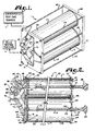
- the reference number 1 generally indicates a calibration apparatus in accordance with the present invention.
- the calibration apparatus 1 is illustrated in Figure 1 as schematically joined to a standard test gas source 5 and a DLco testing machine 6.
- the calibrating apparatus 1 includes a first syringe 10 and a second syringe 11 mounted in a frame 12 with a gas manifold 13 located on the front of the frame 12.
- the first syringe 10 includes a cylindrical shaped body 17 within which is mounted a piston 18.
- the piston 18 includes a sealing member 19 around the perimeter thereof and is sized and shaped to slide within the interior surface 20 of the cylindrical member 17 in a manner such that the sealing member 19 seals as the piston 18 moves along the cylindrical member 17.
- a rod 23 is centrally attached to the piston 18 and has an operator handle 24 located opposite the piston 18 an external of the cylindrical member 17.
- the rod 23 both provides stability to the piston 18 and allows an operator to position the piston 18 within the cylindrical member 17.
- the rod 23 includes a first fixed stop 25 which limits the range of motion of the piston 18 within the cylindrical shaped member 17 for purposes of stability.
- the rod 23 also has positioned thereon an adjustable second stop 27 which is positionable therealong to allow a user to select an initial position for the piston 18 within the cylindrical member 17.
- Located along the rod 23 is a calibrated rule 29 that allows a user to visually and accurately determine the position of the piston 18 relative to the cylindrical member 17.
- the second syringe 11 also includes a cylindrical member 33 within which is mounted a piston 34 with a stabilizing and position adjusting rod 35.
- the rod 35 is mounted and secured to the center of the piston 34 and extends through the frame 12, as will be discussed below'.
- the piston 34 also includes a circumferential and peripheral sealing O-ring 36 that seals with the cylindrical member 33 during use.
- the rod 35 includes a stop 37 to limit the maximum position to which the piston 34 may move within the cylindrical member 33 and an operator handle 38 located opposite the piston 34 outside of the cylindrical member 33.
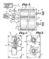
- the frame 12 comprises a front plate 43 and a rear plate 44 joined by six tie rods 45 located in opposing corners of the front plate 43 and rear plate 44 and between the cylindrical members 17 and 33.
- the front plate 43 includes a first recess 47 that is sized and shaped to snugly receive the cylindrical member 17 and a second recess 48, which is likewise sized and shaped to receive the cylindrical member 33.
- Sealing O-rings 49 and 50 also are positioned about the cylindrical members 17 and 33 respectively, and seal with the recesses 47 and 48 respectively.
- the rear plate 44 also includes a pair of recesses 54 and 55.
- the recess 54 is sized and shaped to snugly receive the cylindrical member 17 and includes an O-ring 56 for purpose of stability.
- the recess 55 is sized and shaped to receive the cylindrical member 33 and also includes an O-ring 57 for stability.
- the rear plate 44 also has apertures 60 and 61 therein which are aligned to slideably receive the rods 23 and 35 respectively.
- a series of vent openings 64 passing horizontally through the rear plate 44 and connecting the rear interior of the cylindrical member 17 with ambient air.
- a series of vent openings 65 are positioned around the aperture 61.
- the front plate 43 in the illustrated embodiment is integrally formed with the gas manifold 13, although it is foreseen that the two elements could be manufactured separately.
- the front plate 43 functions in cooperation with the pistons 18 and 34 and their associated cylindrical members 17 and 33 to form variable sized chambers 68 and 69 respectively.
- the chambers 68 and 69 are relatively very small in volume and the volume of the chamber 69 preferably approaches a zero volume as closely as possible when the piston 34 is near the manifold 13.
- the chambers 68 and 69 grow in volume and function to receive selected gasses therein.
- the gas manifold 13 extends forward of the front plate 43, as is seen in Figures 1, 2, and 3.
- the gas manifold 13 includes a first gas passageway 72 and a second gas passageway 73 joined at a frontward end thereof by a multi positional valve 75. Ends of the passageways 72 and 73 opposite the valve 75 operably flow connect with the chambers 68 and 69 respectively.
- the valve 75 is also flow connected with a forward projecting coupling 76 that is sized and shaped to join with the gas discharge and receiving nozzle of a DLco testing machine 6. In this manner, the valve 75 may be set to allow flow from the testing machine 6 to the chamber 68 or alternatively, to allow flow from the chamber 69 to the testing machine 6.
- the valve 75 includes an operator control knob 78.
- Third, fourth and fifth gas passageways 81, 82, and 83 also flow connect with the second gas passageway 73, as is shown in Figure 2.
- the third gas passageway 81 is joined with a quick operating flow control valve 85 mounted on the front of the gas manifold 13.
- the valve 85 also operably flow connects with the standardized test gas source 5 during use and operably provides for an operator using gas from the source 5 to fill the chamber 69 by depression of the valve 85.
- the fourth gas passageway 82 is joined to a relief valve 86 also mounted on the gas manifold 13 to safely relieve over-pressure in the chamber 68, should the chamber 68 inadvertently become over-pressurized.
- the fifth gas passageway 83 is joined by a valve 88 to a vent 89 mounted on the front of the gas manifold 13. The operation of the valve 88 and vent 89 function to allow a user to purge gas that enters the chamber 69 through the valve 85 and also through the second gas passageway 73 in order to assure that the gas in the second gas passageway 73 has a composition that is essentially consistent with the gas composition in the chamber 69.
- the calibration apparatus 1 is joined to any of numerous types of DLco testing machines, such as are illustrated by the block 6 and to a source 5 of standardized test gas.
- the calibration apparatus 1 is then utilized much to mimic testing with a patient.
- the DLco testing machine will normally discharge a quantity of test gas into the patient, sometimes after offering several breaths of normal air to the patient in order to start machine programming or in other cases without such pre-breathing.
- the test gas will be similar in composition to air which may be humidified or otherwise treated to make it similar to a normal breath composition and which will include a small concentration of carbon monoxide, as well as a known quantity of an inert tracer gas.
- the carbon monoxide concentration may be varied with subsequent tests to insure the machine 6 is able to correctly analyze carbon monoxide from a range of patients who have different membrane diffusion, such as athletes and persons with emphysema.
- the valve 75 is initially set to allow the gas from the testing machine 6 to enter or flow into the chamber 68 through the first passageway 72.
- the piston 18 moves away from the gas manifold 13 as gas enters the chamber 68 thereby enlarging the chamber 68.
- the piston 18 may be pre-positioned relative to the cylindrical member 17 away from the gas manifold 13 by location of the second stop 27 therealong. Such positioning will be in accordance with the particular testing being conducted.
- an elapsed time such as 10 seconds
- some series of events is allowed to occur, after which an exhalation of gas into the testing machine 6 occurs.
- a quantity of a test gas with a known concentration of carbon monoxide, which is lower than the concentration of carbon monoxide in the gas discharged by the testing machine 6, is placed in the chamber 68 by operation of the valve 85.
- the chamber 68 will have several volumes, for example 250 milliliters of test gas delivered to it which is then discharged to purge the chamber 68 and gas manifold 13 prior to final filling for conducting the test.
- the gas in the chamber 68 causes the piston 34 to retract or move away from the gas manifold 13 a preselected distance or until the stop 37 engages the rear plate 44.
- the valve 88 and vent 89 may then be operated in such a manner as to discharge some of the gas entering through the valve 85 in such a manner as to sweep or purge the second passageway 73 and thereby remove any stagnant or gas remaining therein, such as ambient air or from a previous test, if a purge has not already been completed.
- the gasses in both the chamber 69 and the second passageway 73 have essentially the same composition, especially with respect to concentration of carbon monoxide. Normally gas will be positioned within the chamber 69 before the calibration or testing is done, but this step could be taken subsequent to the discharge of gas from the machine 6.
- the valve 75 is set to flow connect the coupling 76 with the second passageway 73.
- the piston 34 is then urged toward the front of the cylindrical member 33, that is toward the gas manifold 13, by an operator pushing on the handle 38. This urges the gas that is then in the chamber 69 out of the chamber 69 due to compression of the chamber 69 and through the second passageway 73 to the DLco testing machine 6.
- the DLco testing machine then performs one or more analyses on the test gas to determine whether the DLco machine is correctly analyzing the concentration of carbon monoxide in the gas and/or whether there are any other problems associated with the system that cause the machine 6 to incorrectly analyze the carbon monoxide concentration within the test gas.
- the coupling 76 is mounted as close to the valve 75 as possible, such that dead space, that could hold contaminated or ambient air is reduced to a minimum between the DLco testing machine 6 and the apparatus 1. Because the second gas passageway 73 is purged with test gas and the chance for contamination at the coupling 75 is reduced as much as possible, the gas analyzed by the testing machine 6 has very little likelihood of being contaminated or diluted with ambient air or other gas in the calibrating apparatus 1.
Landscapes
- Health & Medical Sciences (AREA)
- Life Sciences & Earth Sciences (AREA)
- Pulmonology (AREA)
- Medical Informatics (AREA)
- Surgery (AREA)
- Biophysics (AREA)
- Pathology (AREA)
- Engineering & Computer Science (AREA)
- Biomedical Technology (AREA)
- Heart & Thoracic Surgery (AREA)
- Physiology (AREA)
- Molecular Biology (AREA)
- Physics & Mathematics (AREA)
- Animal Behavior & Ethology (AREA)
- General Health & Medical Sciences (AREA)
- Public Health (AREA)
- Veterinary Medicine (AREA)
- Sampling And Sample Adjustment (AREA)
- Investigating Or Analysing Biological Materials (AREA)
- Investigating Or Analysing Materials By Optical Means (AREA)
Claims (12)
- Appareil d'étalonnage permettant d'effectuer un essai opérationnel sur la précision de la machine d'essai DLco ; ledit appareil d'étalonnage comprenant :a) un bâti (12) ;b) une première seringue (10) dotée d'un premier piston mobile (18) formant une première chambre de réception de gaz (68) de taille variable ;c) une deuxième seringue (11) dotée d'un deuxième piston mobile (34) formant une deuxième chambre de réception de gaz (69) de taille variable ;d) un collecteur de gaz (13) raccordé de manière sélective auxdites première et deuxième chambres et, au cours du fonctionnement dudit appareil, conçu pour être raccordé à une machine d'essai (6) ; caractérisé en ce que :e) ledit collecteur (13) comporte un passage de gaz (73) raccordé à ladite deuxième chambre de réception de gaz (69) à l'aide d'un accouplement (76) dimensionné et formé pour s'apparier avec une machine d'essai DLco (6) ; et en ce quef) ledit passage comporte une soupape de commande de débit (75).
- Appareil selon la revendication 1, dans lequel :a) lesdites première (10) et deuxième (11) seringues sont montées côte à côte à proximité l'une de l'autre.
- Appareil selon la revendication 1, dans lequel :b) ledit bâti comporte une plaque avant (43) ;c) lesdits premier et deuxième éléments comportent chacun un élément cylindrique (17, 33) ; etd) ladite plaque avant comporte des premier et deuxième récepteurs ; lesdits récepteurs étant dimensionnés et formés de manière à recevoir les éléments cylindriques respectifs.
- Appareil selon la revendication 1, dans lequel :a) ledit passage de gaz (73) est raccordé à une soupape de source de gaz d'essai (85) qui est à son tour conçue, en utilisation, pour être raccordée à une source de gaz d'essai.
- Appareil selon la revendication 1, comportant :a) un évent (89) relié audit passage de gaz ; ledit évent comportant une soupape d'aération (88) et étant placée à proximité de ladite soupape de commande pour permettre la purge dudit passage grâce à l'ouverture de ladite soupape d'aération.
- Appareil selon la revendication 1, dans lequel :a) ledit passage de gaz est un premier passage de gaz raccordé à ladite deuxième chambre et comportant un deuxième passage de gaz raccordé à ladite première chambre ;b) lesdits premier et deuxième passages étant reliés au niveau de ladite soupape de commande de débit (75) de telle sorte que ladite soupape commande de manière sélective le débit par le biais de l'un desdits passages ; etc) lesdits passages étant raccordés de manière sélective par le biais de ladite soupape à l'accouplement (76) dimensionné et formé de manière à être adapté, en utilisation, pour s'apparier à une machine d'essai DLco.
- Appareil selon la revendication 6, dans lequel :a) ledit accouplement (76) est placé de manière sensiblement adjacente à ladite soupape (75) de manière à réduire au minimum volume mort de gaz entre les deux.
- Appareil selon la revendication 1, dans lequel :a) ledit bâti (12) comporte une plaque arrière (44) ; etb) lesdites première et deuxième seringues (10, 11) comportent des première (23) et deuxième (35) tiges respectivement fixées aux pistons de chacune des seringues respectivement ; lesdites première et deuxième tiges étant reçues dans des ouvertures ménagées dans ladite plaque arrière de manière à s'étendre vers l'extérieur à partir de là.
- Appareil selon la revendication 8, dans lequel :a) ladite plaque arrière (44) comporte des évents (64, 65) associés à chacune desdites seringues.
- Appareil selon la revendication 8, dans lequel :a) ladite première tige comporte une première butée (25) limitant le mouvement vers l'arrière et espaçant au maximum le mouvement vers l'arrière dudit premier piston de seringue d'une paroi arrière de ladite première seringue.
- Appareil selon la revendication 10, dans lequel :a) ladite première tige comporte une deuxième butée ajustable (22) permettant de limiter le mouvement vers l'avant dudit piston de la première seringue par rapport à une paroi arrière de ladite première seringue.
- Appareil selon la revendication 11, dans lequel :a) ladite première tige est étalonnée pour permettre un positionnement précis de ladite deuxième butée.
Applications Claiming Priority (2)
| Application Number | Priority Date | Filing Date | Title |
|---|---|---|---|
| US460626 | 1995-06-02 | ||
| US09/460,626 US6415642B1 (en) | 1999-12-14 | 1999-12-14 | DLco calibration syringe apparatus |
Publications (3)
| Publication Number | Publication Date |
|---|---|
| EP1109018A2 EP1109018A2 (fr) | 2001-06-20 |
| EP1109018A3 EP1109018A3 (fr) | 2002-12-04 |
| EP1109018B1 true EP1109018B1 (fr) | 2007-07-25 |
Family
ID=23829452
Family Applications (1)
| Application Number | Title | Priority Date | Filing Date |
|---|---|---|---|
| EP00309444A Expired - Lifetime EP1109018B1 (fr) | 1999-12-14 | 2000-10-26 | Appareil à seringues pour calibrer un analyseur de la capacité pulmonaire de diffusion de monoxyde de carbone |
Country Status (4)
| Country | Link |
|---|---|
| US (1) | US6415642B1 (fr) |
| EP (1) | EP1109018B1 (fr) |
| AT (1) | ATE368219T1 (fr) |
| DE (1) | DE60035662T2 (fr) |
Families Citing this family (6)
| Publication number | Priority date | Publication date | Assignee | Title |
|---|---|---|---|---|
| CN102715904A (zh) | 2005-05-10 | 2012-10-10 | 恩斯拜尔保健公司 | 用于分析肺性能的设备 |
| US7814774B2 (en) * | 2006-03-27 | 2010-10-19 | Erasmus University Medical Center Rotterdam | Method and apparatus for evaluation of a device for measuring lung diffusion capacity |
| US7972415B2 (en) * | 2008-12-11 | 2011-07-05 | Spx Corporation | Membrane-based compressed air breathing system |
| US9186090B2 (en) | 2012-11-20 | 2015-11-17 | Nspire Health, Inc. | Method and system for DLCO quality control testing |
| US10206608B2 (en) | 2017-06-01 | 2019-02-19 | Nspire Health, Inc. | Apparatus and methods for calibrating and/or validating pulmonary function test equipment |
| JP2021186345A (ja) * | 2020-06-01 | 2021-12-13 | 株式会社フクダ産業 | 肺機能検査装置の較正装置 |
Family Cites Families (13)
| Publication number | Priority date | Publication date | Assignee | Title |
|---|---|---|---|---|
| US3948604A (en) | 1974-01-02 | 1976-04-06 | Borg-Warner Corporation | Alcoholic breath simulation system |
| US4083367A (en) | 1976-07-28 | 1978-04-11 | Andros Incorporated | Method and apparatus for pulmonary function analysis |
| DE2912181C2 (de) | 1979-03-28 | 1981-06-11 | Drägerwerk AG, 2400 Lübeck | Kalibriereinrichtung |
| US4680956A (en) | 1983-11-17 | 1987-07-21 | Research And Education Institute, Inc. Harbor-Ucla Medical Center | Respiratory analyzer calibration apparatus with controlled respiratory gas exchange simulation |
| US5022406A (en) | 1988-08-01 | 1991-06-11 | Tomlinson Harold W | Module for determining diffusing capacity of the lungs for carbon monoxide and method |
| AT398694B (de) * | 1990-07-19 | 1995-01-25 | Avl Verbrennungskraft Messtech | Vorrichtung zur bestimmung der konzentration von zumindest einer in organischem gewebe vorliegenden substanz |
| US5193551A (en) | 1990-07-27 | 1993-03-16 | Pilipski M | Phantom assembly to verify accuracy of a carbon monoxide diffusing capacity measuring device |
| US5119825A (en) | 1991-02-25 | 1992-06-09 | Medical Graphics Corporation | Multi-functional patient valve |
| GB9224304D0 (en) * | 1992-11-19 | 1993-01-06 | Secr Defence | Calibration systems |
| US5303712A (en) * | 1993-01-25 | 1994-04-19 | Medical Graphics Corporation | Calibration method for single-breath carbon monoxide lung diffusing capacity test system |
| US5386833A (en) | 1993-12-23 | 1995-02-07 | Biochem International, Inc. | Method for calibrating a carbon dioxide monitor |
| US5826577A (en) | 1996-01-30 | 1998-10-27 | Bacharach, Inc. | Breath gas analysis module |
| WO1999046572A1 (fr) * | 1998-03-11 | 1999-09-16 | True Technology, Inc. | Procede et dispositif de detection des fuites dans des emballages hermetiques |
-
1999
- 1999-12-14 US US09/460,626 patent/US6415642B1/en not_active Expired - Lifetime
-
2000
- 2000-10-26 AT AT00309444T patent/ATE368219T1/de not_active IP Right Cessation
- 2000-10-26 EP EP00309444A patent/EP1109018B1/fr not_active Expired - Lifetime
- 2000-10-26 DE DE60035662T patent/DE60035662T2/de not_active Expired - Lifetime
Also Published As
| Publication number | Publication date |
|---|---|
| DE60035662D1 (de) | 2007-09-06 |
| EP1109018A2 (fr) | 2001-06-20 |
| DE60035662T2 (de) | 2008-05-21 |
| EP1109018A3 (fr) | 2002-12-04 |
| ATE368219T1 (de) | 2007-08-15 |
| US6415642B1 (en) | 2002-07-09 |
Similar Documents
| Publication | Publication Date | Title |
|---|---|---|
| US5303712A (en) | Calibration method for single-breath carbon monoxide lung diffusing capacity test system | |
| EP2733485B1 (fr) | Procédé et système de test de contrôle de qualité DLCO | |
| CN101340941B (zh) | 用于估计呼气末肺容量的方法和装置 | |
| US5022406A (en) | Module for determining diffusing capacity of the lungs for carbon monoxide and method | |
| JP3553160B2 (ja) | 肺の機能的残気量の決定に関して換気装置を制御する方法および機能的残気量の決定のための換気装置 | |
| US20220117512A1 (en) | Method and Apparatus for Analyzing Pulmonary Performance | |
| JP2005538819A (ja) | 診断用ガス分析装置及び方法 | |
| US5193551A (en) | Phantom assembly to verify accuracy of a carbon monoxide diffusing capacity measuring device | |
| EP1764035B1 (fr) | Outil pour la détermination de la capacité de la diffusion pulmonaire pour une inspiration utilisant la mésure ultrasonore de la masse molaire | |
| US11033202B2 (en) | Method to determine indices of ventilation inhomogeneity e.g. lung clearance index (LCI) of a paediatric test subject | |
| EP1772098B1 (fr) | Tête de mesure pour instruments de diagnostic et procédé | |
| EP1109018B1 (fr) | Appareil à seringues pour calibrer un analyseur de la capacité pulmonaire de diffusion de monoxyde de carbone | |
| US6544191B2 (en) | Process for determining the functional residual capacity of the lungs | |
| US20060000256A1 (en) | System for testing performance of medical gas or vapor analysis apparatus | |
| US20100312134A1 (en) | Apparatus for Evaluation of a Device for Measuring Lung Diffusion Capacity | |
| US20050075552A1 (en) | Device and method for determining the amount of hemoglobin by means of inhalation of a predefined amount of carbon monoxide | |
| CN111329482A (zh) | 肺功能仪测试头、肺功能仪及肺通气测试单元 | |
| JP2000037368A (ja) | 肺機能検査装置 | |
| Floriano et al. | Accuracy of tidal volume delivery by five different models of large-animal ventilators | |
| US7114367B1 (en) | Pulmonary function test calibration system and method | |
| CN212234447U (zh) | 肺功能仪测试头、肺功能仪及肺通气测试单元 | |
| CN115886784A (zh) | 一种弥散肺功能仪的测试系统和测试装置 | |
| Hopster et al. | Evaluation of the effects of gas volume and composition on accuracy of volume measurement by two flow sensors and delivery by a piston-driven large-animal ventilator | |
| CN115721292A (zh) | 一种肺功能仪的测试系统及测试装置 | |
| Craine et al. | Microcomputer based instrument for measuring a novel pulmonary function test |
Legal Events
| Date | Code | Title | Description |
|---|---|---|---|
| PUAI | Public reference made under article 153(3) epc to a published international application that has entered the european phase |
Free format text: ORIGINAL CODE: 0009012 |
|
| AK | Designated contracting states |
Kind code of ref document: A2 Designated state(s): AT BE CH CY DE DK ES FI FR GB GR IE IT LI LU MC NL PT SE |
|
| AX | Request for extension of the european patent |
Free format text: AL;LT;LV;MK;RO;SI |
|
| PUAL | Search report despatched |
Free format text: ORIGINAL CODE: 0009013 |
|
| AK | Designated contracting states |
Kind code of ref document: A3 Designated state(s): AT BE CH CY DE DK ES FI FR GB GR IE IT LI LU MC NL PT SE |
|
| AX | Request for extension of the european patent |
Free format text: AL;LT;LV;MK;RO;SI |
|
| 17P | Request for examination filed |
Effective date: 20030303 |
|
| AKX | Designation fees paid |
Designated state(s): AT BE CH CY DE DK ES FI FR GB GR IE IT LI LU MC NL PT SE |
|
| GRAP | Despatch of communication of intention to grant a patent |
Free format text: ORIGINAL CODE: EPIDOSNIGR1 |
|
| GRAS | Grant fee paid |
Free format text: ORIGINAL CODE: EPIDOSNIGR3 |
|
| GRAA | (expected) grant |
Free format text: ORIGINAL CODE: 0009210 |
|
| AK | Designated contracting states |
Kind code of ref document: B1 Designated state(s): AT BE CH CY DE DK ES FI FR GB GR IE IT LI LU MC NL PT SE |
|
| REG | Reference to a national code |
Ref country code: GB Ref legal event code: FG4D |
|
| REG | Reference to a national code |
Ref country code: CH Ref legal event code: EP |
|
| REG | Reference to a national code |
Ref country code: IE Ref legal event code: FG4D |
|
| REF | Corresponds to: |
Ref document number: 60035662 Country of ref document: DE Date of ref document: 20070906 Kind code of ref document: P |
|
| ET | Fr: translation filed | ||
| PG25 | Lapsed in a contracting state [announced via postgrant information from national office to epo] |
Ref country code: NL Free format text: LAPSE BECAUSE OF FAILURE TO SUBMIT A TRANSLATION OF THE DESCRIPTION OR TO PAY THE FEE WITHIN THE PRESCRIBED TIME-LIMIT Effective date: 20070725 Ref country code: FI Free format text: LAPSE BECAUSE OF FAILURE TO SUBMIT A TRANSLATION OF THE DESCRIPTION OR TO PAY THE FEE WITHIN THE PRESCRIBED TIME-LIMIT Effective date: 20070725 Ref country code: ES Free format text: LAPSE BECAUSE OF FAILURE TO SUBMIT A TRANSLATION OF THE DESCRIPTION OR TO PAY THE FEE WITHIN THE PRESCRIBED TIME-LIMIT Effective date: 20071105 Ref country code: PT Free format text: LAPSE BECAUSE OF FAILURE TO SUBMIT A TRANSLATION OF THE DESCRIPTION OR TO PAY THE FEE WITHIN THE PRESCRIBED TIME-LIMIT Effective date: 20071226 |
|
| REG | Reference to a national code |
Ref country code: CH Ref legal event code: PL |
|
| NLV1 | Nl: lapsed or annulled due to failure to fulfill the requirements of art. 29p and 29m of the patents act | ||
| PG25 | Lapsed in a contracting state [announced via postgrant information from national office to epo] |
Ref country code: LI Free format text: LAPSE BECAUSE OF FAILURE TO SUBMIT A TRANSLATION OF THE DESCRIPTION OR TO PAY THE FEE WITHIN THE PRESCRIBED TIME-LIMIT Effective date: 20070725 Ref country code: AT Free format text: LAPSE BECAUSE OF FAILURE TO SUBMIT A TRANSLATION OF THE DESCRIPTION OR TO PAY THE FEE WITHIN THE PRESCRIBED TIME-LIMIT Effective date: 20070725 Ref country code: CH Free format text: LAPSE BECAUSE OF FAILURE TO SUBMIT A TRANSLATION OF THE DESCRIPTION OR TO PAY THE FEE WITHIN THE PRESCRIBED TIME-LIMIT Effective date: 20070725 |
|
| PG25 | Lapsed in a contracting state [announced via postgrant information from national office to epo] |
Ref country code: BE Free format text: LAPSE BECAUSE OF FAILURE TO SUBMIT A TRANSLATION OF THE DESCRIPTION OR TO PAY THE FEE WITHIN THE PRESCRIBED TIME-LIMIT Effective date: 20070725 |
|
| PG25 | Lapsed in a contracting state [announced via postgrant information from national office to epo] |
Ref country code: DK Free format text: LAPSE BECAUSE OF FAILURE TO SUBMIT A TRANSLATION OF THE DESCRIPTION OR TO PAY THE FEE WITHIN THE PRESCRIBED TIME-LIMIT Effective date: 20070725 Ref country code: GR Free format text: LAPSE BECAUSE OF FAILURE TO SUBMIT A TRANSLATION OF THE DESCRIPTION OR TO PAY THE FEE WITHIN THE PRESCRIBED TIME-LIMIT Effective date: 20071026 |
|
| PG25 | Lapsed in a contracting state [announced via postgrant information from national office to epo] |
Ref country code: MC Free format text: LAPSE BECAUSE OF NON-PAYMENT OF DUE FEES Effective date: 20071031 |
|
| PLBE | No opposition filed within time limit |
Free format text: ORIGINAL CODE: 0009261 |
|
| STAA | Information on the status of an ep patent application or granted ep patent |
Free format text: STATUS: NO OPPOSITION FILED WITHIN TIME LIMIT |
|
| PG25 | Lapsed in a contracting state [announced via postgrant information from national office to epo] |
Ref country code: SE Free format text: LAPSE BECAUSE OF FAILURE TO SUBMIT A TRANSLATION OF THE DESCRIPTION OR TO PAY THE FEE WITHIN THE PRESCRIBED TIME-LIMIT Effective date: 20071025 |
|
| 26N | No opposition filed |
Effective date: 20080428 |
|
| PG25 | Lapsed in a contracting state [announced via postgrant information from national office to epo] |
Ref country code: IE Free format text: LAPSE BECAUSE OF NON-PAYMENT OF DUE FEES Effective date: 20071026 |
|
| PG25 | Lapsed in a contracting state [announced via postgrant information from national office to epo] |
Ref country code: CY Free format text: LAPSE BECAUSE OF FAILURE TO SUBMIT A TRANSLATION OF THE DESCRIPTION OR TO PAY THE FEE WITHIN THE PRESCRIBED TIME-LIMIT Effective date: 20070725 |
|
| PG25 | Lapsed in a contracting state [announced via postgrant information from national office to epo] |
Ref country code: LU Free format text: LAPSE BECAUSE OF NON-PAYMENT OF DUE FEES Effective date: 20071026 |
|
| REG | Reference to a national code |
Ref country code: FR Ref legal event code: PLFP Year of fee payment: 16 |
|
| REG | Reference to a national code |
Ref country code: FR Ref legal event code: PLFP Year of fee payment: 17 |
|
| PGFP | Annual fee paid to national office [announced via postgrant information from national office to epo] |
Ref country code: GB Payment date: 20160801 Year of fee payment: 17 |
|
| PGFP | Annual fee paid to national office [announced via postgrant information from national office to epo] |
Ref country code: FR Payment date: 20161028 Year of fee payment: 17 |
|
| PGFP | Annual fee paid to national office [announced via postgrant information from national office to epo] |
Ref country code: IT Payment date: 20161024 Year of fee payment: 17 |
|
| PGFP | Annual fee paid to national office [announced via postgrant information from national office to epo] |
Ref country code: DE Payment date: 20161223 Year of fee payment: 17 |
|
| REG | Reference to a national code |
Ref country code: DE Ref legal event code: R119 Ref document number: 60035662 Country of ref document: DE |
|
| GBPC | Gb: european patent ceased through non-payment of renewal fee |
Effective date: 20171026 |
|
| REG | Reference to a national code |
Ref country code: FR Ref legal event code: ST Effective date: 20180629 |
|
| PG25 | Lapsed in a contracting state [announced via postgrant information from national office to epo] |
Ref country code: GB Free format text: LAPSE BECAUSE OF NON-PAYMENT OF DUE FEES Effective date: 20171026 Ref country code: DE Free format text: LAPSE BECAUSE OF NON-PAYMENT OF DUE FEES Effective date: 20180501 |
|
| PG25 | Lapsed in a contracting state [announced via postgrant information from national office to epo] |
Ref country code: FR Free format text: LAPSE BECAUSE OF NON-PAYMENT OF DUE FEES Effective date: 20171031 |
|
| PG25 | Lapsed in a contracting state [announced via postgrant information from national office to epo] |
Ref country code: IT Free format text: LAPSE BECAUSE OF NON-PAYMENT OF DUE FEES Effective date: 20171026 |