EP1108941A1 - Leitungsverbinder insbesondere für Kraftstoffleitungen - Google Patents
Leitungsverbinder insbesondere für Kraftstoffleitungen Download PDFInfo
- Publication number
- EP1108941A1 EP1108941A1 EP00126566A EP00126566A EP1108941A1 EP 1108941 A1 EP1108941 A1 EP 1108941A1 EP 00126566 A EP00126566 A EP 00126566A EP 00126566 A EP00126566 A EP 00126566A EP 1108941 A1 EP1108941 A1 EP 1108941A1
- Authority
- EP
- European Patent Office
- Prior art keywords
- line
- connecting body
- connector according
- connection element
- transition section
- Prior art date
- Legal status (The legal status is an assumption and is not a legal conclusion. Google has not performed a legal analysis and makes no representation as to the accuracy of the status listed.)
- Granted
Links
- 239000000446 fuel Substances 0.000 title claims description 8
- 230000007704 transition Effects 0.000 claims abstract description 29
- 238000000034 method Methods 0.000 claims abstract description 5
- 239000000463 material Substances 0.000 claims description 15
- 230000008878 coupling Effects 0.000 claims description 8
- 238000010168 coupling process Methods 0.000 claims description 8
- 238000005859 coupling reaction Methods 0.000 claims description 8
- 229920001169 thermoplastic Polymers 0.000 claims description 8
- 239000004416 thermosoftening plastic Substances 0.000 claims description 8
- 239000000835 fiber Substances 0.000 claims description 6
- 230000002787 reinforcement Effects 0.000 claims description 6
- 239000013013 elastic material Substances 0.000 claims description 3
- 229920001971 elastomer Polymers 0.000 claims description 3
- 238000010137 moulding (plastic) Methods 0.000 claims description 3
- 229920000034 Plastomer Polymers 0.000 claims description 2
- 239000000806 elastomer Substances 0.000 claims description 2
- 238000001746 injection moulding Methods 0.000 claims description 2
- 238000003780 insertion Methods 0.000 claims 1
- 230000037431 insertion Effects 0.000 claims 1
- 239000004033 plastic Substances 0.000 abstract description 6
- 229920003023 plastic Polymers 0.000 abstract description 6
- 238000000465 moulding Methods 0.000 abstract description 3
- 238000009472 formulation Methods 0.000 description 2
- 239000003365 glass fiber Substances 0.000 description 2
- 238000004519 manufacturing process Methods 0.000 description 2
- 239000000203 mixture Substances 0.000 description 2
- 238000007493 shaping process Methods 0.000 description 2
- 230000015572 biosynthetic process Effects 0.000 description 1
- 230000000694 effects Effects 0.000 description 1
- 238000002347 injection Methods 0.000 description 1
- 239000007924 injection Substances 0.000 description 1
- 238000003825 pressing Methods 0.000 description 1
- 230000035939 shock Effects 0.000 description 1
- 238000005507 spraying Methods 0.000 description 1
- 230000003068 static effect Effects 0.000 description 1
- 229920001187 thermosetting polymer Polymers 0.000 description 1
Images

Classifications
-
- F—MECHANICAL ENGINEERING; LIGHTING; HEATING; WEAPONS; BLASTING
- F16—ENGINEERING ELEMENTS AND UNITS; GENERAL MEASURES FOR PRODUCING AND MAINTAINING EFFECTIVE FUNCTIONING OF MACHINES OR INSTALLATIONS; THERMAL INSULATION IN GENERAL
- F16L—PIPES; JOINTS OR FITTINGS FOR PIPES; SUPPORTS FOR PIPES, CABLES OR PROTECTIVE TUBING; MEANS FOR THERMAL INSULATION IN GENERAL
- F16L37/00—Couplings of the quick-acting type
- F16L37/08—Couplings of the quick-acting type in which the connection between abutting or axially overlapping ends is maintained by locking members
- F16L37/084—Couplings of the quick-acting type in which the connection between abutting or axially overlapping ends is maintained by locking members combined with automatic locking
-
- F—MECHANICAL ENGINEERING; LIGHTING; HEATING; WEAPONS; BLASTING
- F16—ENGINEERING ELEMENTS AND UNITS; GENERAL MEASURES FOR PRODUCING AND MAINTAINING EFFECTIVE FUNCTIONING OF MACHINES OR INSTALLATIONS; THERMAL INSULATION IN GENERAL
- F16L—PIPES; JOINTS OR FITTINGS FOR PIPES; SUPPORTS FOR PIPES, CABLES OR PROTECTIVE TUBING; MEANS FOR THERMAL INSULATION IN GENERAL
- F16L27/00—Adjustable joints; Joints allowing movement
- F16L27/10—Adjustable joints; Joints allowing movement comprising a flexible connection only
- F16L27/107—Adjustable joints; Joints allowing movement comprising a flexible connection only the ends of the pipe being interconnected by a flexible sleeve
-
- F—MECHANICAL ENGINEERING; LIGHTING; HEATING; WEAPONS; BLASTING
- F16—ENGINEERING ELEMENTS AND UNITS; GENERAL MEASURES FOR PRODUCING AND MAINTAINING EFFECTIVE FUNCTIONING OF MACHINES OR INSTALLATIONS; THERMAL INSULATION IN GENERAL
- F16L—PIPES; JOINTS OR FITTINGS FOR PIPES; SUPPORTS FOR PIPES, CABLES OR PROTECTIVE TUBING; MEANS FOR THERMAL INSULATION IN GENERAL
- F16L27/00—Adjustable joints; Joints allowing movement
- F16L27/10—Adjustable joints; Joints allowing movement comprising a flexible connection only
- F16L27/107—Adjustable joints; Joints allowing movement comprising a flexible connection only the ends of the pipe being interconnected by a flexible sleeve
- F16L27/108—Adjustable joints; Joints allowing movement comprising a flexible connection only the ends of the pipe being interconnected by a flexible sleeve the sleeve having the form of a bellows with only one corrugation
-
- F—MECHANICAL ENGINEERING; LIGHTING; HEATING; WEAPONS; BLASTING
- F16—ENGINEERING ELEMENTS AND UNITS; GENERAL MEASURES FOR PRODUCING AND MAINTAINING EFFECTIVE FUNCTIONING OF MACHINES OR INSTALLATIONS; THERMAL INSULATION IN GENERAL
- F16L—PIPES; JOINTS OR FITTINGS FOR PIPES; SUPPORTS FOR PIPES, CABLES OR PROTECTIVE TUBING; MEANS FOR THERMAL INSULATION IN GENERAL
- F16L27/00—Adjustable joints; Joints allowing movement
- F16L27/10—Adjustable joints; Joints allowing movement comprising a flexible connection only
- F16L27/107—Adjustable joints; Joints allowing movement comprising a flexible connection only the ends of the pipe being interconnected by a flexible sleeve
- F16L27/11—Adjustable joints; Joints allowing movement comprising a flexible connection only the ends of the pipe being interconnected by a flexible sleeve the sleeve having the form of a bellows with multiple corrugations
-
- F—MECHANICAL ENGINEERING; LIGHTING; HEATING; WEAPONS; BLASTING
- F16—ENGINEERING ELEMENTS AND UNITS; GENERAL MEASURES FOR PRODUCING AND MAINTAINING EFFECTIVE FUNCTIONING OF MACHINES OR INSTALLATIONS; THERMAL INSULATION IN GENERAL
- F16L—PIPES; JOINTS OR FITTINGS FOR PIPES; SUPPORTS FOR PIPES, CABLES OR PROTECTIVE TUBING; MEANS FOR THERMAL INSULATION IN GENERAL
- F16L51/00—Expansion-compensation arrangements for pipe-lines
- F16L51/02—Expansion-compensation arrangements for pipe-lines making use of a bellows or an expansible folded or corrugated tube
Definitions
- the present invention relates to a line connector for pipe and / or Hose lines, in particular fuel lines, consisting of a connecting body with at least one line connection element.
- Line connectors of the type mentioned consist predominantly of today Plastic.
- the line connection element is usually a mandrel profile (drive-in mandrel) designed for non-positive and / or positive connection of a line.
- the connecting body can be used as a coupling housing for a connector or Socket part of a plug coupling can be formed.
- Such line connectors will be used for example in motor vehicles in the field of fuel lines.
- accident-related (crash-related) deformations of the vehicle problematic, because This leads to collisions of the line connector with engine and / or body parts can come.
- the connector may break, and the consequent leakage leads to fuel leakage, which ignite on contact with hot engine parts and thus a vehicle fire could cause.
- FR-A-2 257 841 describes a plastic sleeve for connecting two pipes, on both sides by a union nut on the respective tube is pressed. This cuff only acts as a kind of expansion joint.
- US-A-4 810 008 describes a connector (fitting) for pipes in sprinkler systems, a simple exchange of leaky parts, e.g. B. pipe sections allow should.
- the connector has pipe connections that are bellows-like Intermediate sections are longitudinally movable in such a way that they are pushed axially onto the line and can be glued.
- GB-A-2 120 341 discloses a deformable tube connector with one of one metallic corrugated tube formed, bellows or bellows section, the is plastically bendable by any angle.
- the present invention has for its object a line connector to improve the type described at the beginning so that the risk of damage, in particular breaks, due to an externally applied, especially crash-related Power is significantly reduced.
- the connector should still be simple and be inexpensive to manufacture.
- this is achieved in that the (or each) line connection element over such an elastically and / or plastically deformable transition section is connected to the connecting body that it is relative to the connecting body while maintaining the media tightness across a push-on axis the line is bendable or kinkable, the line connection element with the transition section and the connecting body of a one-piece, monolithic in a plastic molding process in a multi-component injection molding process formed from at least two different materials molded part is.
- connection section with regard to its material-specific and / or shape-related Properties in particular empirically designed so that a given Deformation without leakage is possible.
- thermoplastic without fiber reinforcement for the connecting section in particular PA 12
- the remaining sections consist of one, in particular the same, thermoplastic, but with fiber reinforcement, in particular Glass fiber content, preferably consist of PA 12-23% GF.
- these Materials are also preferably electrically conductive formulations with regard to the preferred use in the fuel sector, static charges and to avoid sparking that may result.
- the formation as a one-piece, monolithically injection molded Molding the manufacture nevertheless simple and inexpensive.
- An inventive line connector 1 is used to connect at least one Pipe or hose line (not shown), in particular a fuel line.
- the line connector 1 consists of a connecting body 2 with at least a line connection element 4.
- the line connection element 4 is preferably a conventional mandrel profile (drive-in mandrel) trained to attach a line.
- the mandrel profile several, arranged distributed over its length, in the circumferential direction continuously extending holding ribs 6 with a barb-like contour. Thereby becomes an at least non-positive, but in particular non-positive holder the attached line reached.
- the line connection element 4 on its side facing the connecting body 2 a radially extending Ring ring 8 have.
- the connecting body 2 is preferably a coupling housing of a plug-in coupling educated.
- the clutch housing forms Socket part with a receiving opening for inserting one indicated only by dashed lines Plug part 10.
- the line connection element 4 is related a plug-on axis 12 of the line and, on the other hand, the connecting body 2 with respect to a plug axis 14 of the plug coupling coaxial, i.e. in the axial direction aligned, arranged one behind the other. But it’s quite different, practically any angular arrangement between the connecting body 2 and the Line connection element 4 possible.
- the line connection element 4 is relative to the connecting body 2 movable under certain elastic and / or plastic deformation, and Although it can be bent or even bent, seen transversely to the plug-on axis 12, without this would cause the pipe connection to leak.
- This is the line connection element 4, preferably via a transition section 16 that is deformable in itself connected to the connecting body 2.
- the line connection element 4 with the transition section 16 and the connecting body 2 of a one-piece, monolithically made in a molding process from plastic Molding 18 formed.
- the transition section 16 can be material-specific and / or properties due to shaping its deformability according to the invention get, causing a kink by up to at least 90) below Maintaining media tightness is possible.
- FIGS. 3 and 4 are predominantly material-specific Properties that are responsible for the deformability of the transition section 16 are.
- the transition section 16 has a special shaping, which mainly causes deformability, with additional but also the material-specific properties are important.
- the molded part 18 is produced in a multicomponent spraying process in all of its versions from at least two different plastic materials manufactured.
- the transition section 16 consists of a more elastic material, while the line connection element 4 and the connecting body 2 each a less elastic, more dimensionally stable material. Basically you can the connecting body 2 and the line connection element 4 also from different Materials exist.
- the transition section 16 consists on the one hand a thermoplastic without fiber reinforcement and on the other hand the line connection element 4 and / or the connecting body 2 made of a thermoplastic with fiber reinforcement.
- the base material in particular PA 12
- a glass fiber portion is added (preferably about 23% GF).
- the transition section 16 can also consist of an elastomer, and for the Connection body 2 and / or the line connection element 4 can be a suitable one Plastomer material can be used, e.g. B. a thermoset or thermoplastic.
- the line connection element 4 is due the deformability of the transition section 16 relative to the connecting body 2 can be tilted in the transverse direction (double arrow 20), but optionally also in addition in the axial direction by compressing or lengthening the transition section 16 movable (double arrow 22 in Figs. 1 and 2). Due to the tiltability in the double arrow direction 20 consequently changes the angle between the axes 12 and 14.
- the transition section 16 widens starting from the line connection element 4 essentially approximately conically in the direction of the connecting body 2.
- the transition section 16 partially bellows-like or bellows-like, especially with a dilute Wrinkled or corrugated wall 24 designed in the manner of a corrugated tube executed.
- the transition section is 16th throughout hollow cylindrical with essentially constant over its length in particular Wall thickness (constant inside and outside diameter). The exact Dimensions, especially the inner and outer diameters, are being adjusted the material-specific properties of the respective material in particular empirically and taking into account the dimensions (e.g. nominal size) of the to fix the (pipe) line mounted on the line connection element 4.
- L: d is approximately in the range from 2.5: 1 to 3.5: 1, in particular approximately 2.7: 1 to 3: 1.
- the unbreakable deformability according to the invention makes it suitable for practical use at e.g. Accidental shock loads, breaks in the area of the cable connector 1 and fuel leakage resulting therefrom avoided, so that advantageously the risk of fire inside a vehicle is also significantly reduced.
- the invention is not based on the illustrated and described exemplary embodiments limited, but also includes all those having the same effect within the meaning of the invention Executions. Furthermore, the invention is not yet based on the claims 1 defined combination of features limited, but can also by any different combination of certain features of all of the total disclosed Individual characteristics must be defined. This means that practically everything Individual feature of claim 1 omitted or by at least one other Instead of the individual feature disclosed the application can be replaced. To that extent is claim 1 merely as a first attempt at formulation for an invention to understand.
Landscapes
- Engineering & Computer Science (AREA)
- General Engineering & Computer Science (AREA)
- Mechanical Engineering (AREA)
- Quick-Acting Or Multi-Walled Pipe Joints (AREA)
- Rigid Pipes And Flexible Pipes (AREA)
- Fuel-Injection Apparatus (AREA)
Abstract
Description
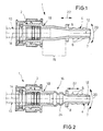
- Fig. 1
- einen Längsschnitt durch eine erste Ausführungsform eines erfindungsgemäßen Leitungsverbinders,
- Fig. 2
- eine Ansicht analog zu Fig. 1 einer zweiten Ausführungsform des Leitungsverbinders,
- Fig. 3
- eine Perspektivansicht einer dritten, bevorzugten Ausführung des Leitungsverbinders und
- Fig. 4
- einen gegenüber Fig. 3 vergrößerten Längsschnitt durch diese Ausführung.
Claims (14)
- Leitungsverbinder (1) für Rohr- und/oder Schlauchleitungen, insbesondere Kraftstoffleitungen, bestehend aus einem Verbindungskörper (2) mit mindestens einem Leitungsanschlußelement (4),
dadurch gekennzeichnet, dass das bzw. jedes Leitungsanschlußelement (4) über einen derart elastisch und/oder plastisch verformbaren Übergangsabschnitt (16) mit dem Verbindungskörper (2) verbunden ist, daß es relativ zu dem Verbindungskörper (2) unter Aufrechterhaltung der Mediendichtheit quer zu einer Aufsteckachse (12) der Leitung abbiegbar bzw. abknickbar ist, wobei das Leitungsanschlußelement (4) mit dem Übergangsabschnitt (16) und dem Verbindungskörper (2) von einem einteiligen, monolithisch in einem Kunststoff-Formvorgang in einem Mehrkomponenten-Spritzverfahren aus mindestens zwei verschiedenen Materialien hergestellten Formteil (18) gebildet ist. - Leitungsverbinder nach Anspruch 1,
dadurch gekennzeichnet, dass das Formteil (18) einerseits im Bereich des Übergangsabschnittes (16) aus einem relativ elastischen Material und andererseits im Bereich des Leitungsanschlußelementes (4) und/oder des Verbindungskörpers (2) jeweils aus einem weniger elastischen Material besteht. - Leitungsverbinder nach Anspruch 2,
dadurch gekennzeichnet, dass einerseits der Übergangsabschnitt (16) aus einem Thermoplast ohne Faserverstärkung, insbesondere PA 12, und andererseits das Leitungsanschlußelement (4) und/oder der Verbindungskörper (2) aus einem Thermoplast mit Faserverstärkung, insbesondere PA 12 - ca. 23% GF, bestehen. - Leitungsverbinder nach Anspruch 2,
dadurch gekennzeichnet, dass einerseits der Übergangsabschnitt (16) aus einem Elastomer und andererseits das Leitungsanschlußelement (4) und/oder der Verbindungskörper (2) aus einem Plastomer bestehen. - Leitungsverbinder nach einem der Ansprüche 1 bis 4,
dadurch gekennzeichnet,dass der Übergangsabschnitt (16) durch seine materialspezifischen und gegebenenfalls zusätzlich durch formungsbedingte Eigenschaften verformbar ist. - Leitungsverbinder nach einem der Ansprüche 1 bis 5,
dadurch gekennzeichnet,dass das Leitungsanschlußelement (4) als Dornprofil zum kraft- und/oder formschlüssigen Aufstecken einer Leitung ausgebildet ist. - Leitungsverbinder nach einem der Ansprüche 1 bis 6,
dadurch gekennzeichnet,dass der Verbindungskörper (2) als Kupplungsgehäuse eines Stecker- oder Muffenteils einer Steckkupplung ausgebildet ist. - Leitungsverbinder nach Anspruch 6 oder 7,
dadurch gekennzeichnet,dassdasLeitungsanschlußelement(4) bezüglich der Aufsteckachse (12) der Leitung und der Verbindungskörper (2) bezüglich einer Steckachse (14) der Steckkupplung koaxial ausgerichtet sind. - Leitungsverbinder nach einem der Ansprüche 1 bis 8,
dadurch gekennzeichnet,dass das Leitungsanschlußelement (4) relativ zu dem Verbindungskörper (2) zusätzlich in Axialrichtung bewegbar ist. - Leitungsverbinder nach einem der Ansprüche 1 bis 9,
dadurch gekennzeichnet,dass der Übergangsabschnitt (16) sich ausgehend von dem Leitungsanschlußelement (4) in Richtung des Verbindungskörpers (2) im Wesentlichen etwa konisch erweitert. - Leitungsverbinder nach einem der Ansprüche 1 bis 10,
dadurch gekennzeichnet,dass der Übergangsabschnitt (16) zumindest bereichsweise falten- oder wellenbalgartig ausgebildet ist. - Leitungsverbinder nach einem der Ansprüche 1 bis 9,
dadurch gekennzeichnet, dass der Übergangsabschnitt (16) hohlzylindrisch ausgebildet ist. - Leitungsverbinder nach einem der Ansprüche 1 bis 12,
dadurch gekennzeichnet, dass das Leitungsanschlußelement (4) in seinem einem freien Einsteckende (7) gegenüberliegenden Bereich ein Widerlagerelement insbesondere in Form eines radialen Ringsteges (8) aufweist. - Leitungsverbinder nach einem der Ansprüche 1 bis 13,
dadurch gekennzeichnet, dass das Verhältnis der Länge (L) des Übergangsabschnittes (16) zu dessen Außendurchmesser (d) mindestens etwa 2:1 beträgt und insbesondere etwa im Bereich von 2,5:1 bis 3,5:1 liegt.
Applications Claiming Priority (2)
| Application Number | Priority Date | Filing Date | Title |
|---|---|---|---|
| DE29922230U | 1999-12-17 | ||
| DE29922230U DE29922230U1 (de) | 1999-12-17 | 1999-12-17 | Leitungsverbinder insbesondere für Kraftstoffleitungen |
Publications (2)
| Publication Number | Publication Date |
|---|---|
| EP1108941A1 true EP1108941A1 (de) | 2001-06-20 |
| EP1108941B1 EP1108941B1 (de) | 2003-11-05 |
Family
ID=8083143
Family Applications (1)
| Application Number | Title | Priority Date | Filing Date |
|---|---|---|---|
| EP00126566A Expired - Lifetime EP1108941B1 (de) | 1999-12-17 | 2000-12-12 | Leitungsverbinder insbesondere für Kraftstoffleitungen |
Country Status (3)
| Country | Link |
|---|---|
| US (2) | US6578878B2 (de) |
| EP (1) | EP1108941B1 (de) |
| DE (2) | DE29922230U1 (de) |
Cited By (4)
| Publication number | Priority date | Publication date | Assignee | Title |
|---|---|---|---|---|
| EP1898138A1 (de) * | 2006-09-08 | 2008-03-12 | Dresser Wayne Aktiebolag | Federbelastete Drehdichtung für Kraftstoffzapfanlage |
| CN103727352A (zh) * | 2013-11-26 | 2014-04-16 | 南通威明精工机械有限公司 | 一种软管衬套 |
| DE102005013981B4 (de) * | 2005-03-26 | 2015-11-26 | Volkswagen Ag | Elektrisch leitfähige Steckkupplung zum Verbinden von fluidführenden Bauteilen |
| EP2977667A1 (de) * | 2014-07-23 | 2016-01-27 | Paccar Inc | Schnellschlussverbinder |
Families Citing this family (13)
| Publication number | Priority date | Publication date | Assignee | Title |
|---|---|---|---|---|
| US6805383B2 (en) * | 2001-11-12 | 2004-10-19 | Itt Manufacturing Enterprises, Inc. | Fluid quick connector with secure electrical contact |
| US7520919B2 (en) * | 2004-06-22 | 2009-04-21 | Gambro Lundia Ab | Transducer-protector device for medical apparatus |
| EP1907709B1 (de) * | 2005-07-22 | 2009-03-11 | Dayco Fluid Technologies S.p.A. | Dämpfungsleitungsanordnung mit einer verbindungseinheit für einen hydraulikkreislauf |
| GB2440521B (en) * | 2006-08-02 | 2011-06-08 | Nissan Motor Mfg | Fuel delivery module and adapter |
| US8297660B2 (en) * | 2007-07-07 | 2012-10-30 | Electrolux Home Products Corporation N.V. | Water-conducting household appliance |
| US8505701B2 (en) * | 2010-08-18 | 2013-08-13 | Autoliv Asp, Inc. | Mass-damper system |
| DE102012004165A1 (de) | 2012-03-05 | 2013-09-05 | Voss Automotive Gmbh | Kontollsystem und Verfahren zur Kontrolle der Montage einer Kupplungseinrichtung |
| DE102014007409A1 (de) * | 2014-03-14 | 2015-09-17 | Voss Automotive Gmbh | Leitungsverbindungseinrichtung zum lösbaren Verbinden von Medienleitungen oder zumindest einer Medienleitung und zumindest eines Aggregats |
| USD758555S1 (en) * | 2015-01-09 | 2016-06-07 | Bi-Phase Technologies, Llc | Fuel line connector |
| CN106287028A (zh) * | 2016-09-29 | 2017-01-04 | 奇瑞汽车股份有限公司 | 一种液体输送管道、冷却系统及汽车 |
| FR3107582A1 (fr) * | 2020-02-26 | 2021-08-27 | Psa Automobiles Sa | Raccord rapide de tuyaux avec anneau en elastomere donnant une flexibilite |
| DK181286B1 (en) * | 2021-04-07 | 2023-06-21 | Hydrosafe Aps | Manchet til en kobling |
| US12516758B2 (en) * | 2022-11-22 | 2026-01-06 | The Boeing Company | Quick connect sleeve |
Citations (4)
| Publication number | Priority date | Publication date | Assignee | Title |
|---|---|---|---|---|
| FR1519744A (fr) | 1967-02-20 | 1968-04-05 | Pneumatiques Caoutchouc Mfg | Manchon de raccordement élastique pour tuyauterie |
| FR2257841A1 (en) | 1974-01-15 | 1975-08-08 | Rago John | Plastic pipe coupling with central bellows - has threaded halves receiving lock nuts and welded together |
| GB2120341A (en) | 1982-05-12 | 1983-11-30 | Gilardini Spa | A deformable tubular connector |
| US4810008A (en) | 1987-06-22 | 1989-03-07 | Scott Brodie | Method and apparatus for repairing lawn sprinkler systems |
Family Cites Families (10)
| Publication number | Priority date | Publication date | Assignee | Title |
|---|---|---|---|---|
| US1869059A (en) * | 1930-10-07 | 1932-07-26 | Alfred J Hanson | Pipe and cigar and cigarette holder cleaner |
| US2711331A (en) * | 1949-07-08 | 1955-06-21 | Temple Robert | Self-tightening conduit couplings |
| US2789654A (en) * | 1954-06-07 | 1957-04-23 | Zurit David | Apparatus for filtering air or gas that enters beer kegs |
| US3727953A (en) * | 1969-02-05 | 1973-04-17 | Advanced Drainage Syst Inc | Tube coupling |
| JPH0618123Y2 (ja) * | 1989-11-11 | 1994-05-11 | 日東工器株式会社 | 管継手のソケット |
| US5720656A (en) * | 1995-10-16 | 1998-02-24 | Savage; Brian T. | Aircraft air conditioning hose |
| DE69622151T2 (de) * | 1995-12-13 | 2003-03-06 | Sherwood Services Ag, Schaffhausen | Dichte rohrverbindungsstelle |
| US5732724A (en) * | 1996-05-15 | 1998-03-31 | Ecolab Inc. | Sink mounted water agitation |
| JP3343581B2 (ja) * | 1997-10-27 | 2002-11-11 | 独立行政法人産業技術総合研究所 | 真空防振継手 |
| FR2787549B1 (fr) * | 1998-12-16 | 2001-01-19 | Nobel Plastiques | Element tubulaire de conduite comportant une partie longitudinale rigide et une partie longitudinale souple en une seule piece |
-
1999
- 1999-12-17 DE DE29922230U patent/DE29922230U1/de not_active Expired - Lifetime
-
2000
- 2000-12-12 DE DE50004314T patent/DE50004314D1/de not_active Expired - Lifetime
- 2000-12-12 EP EP00126566A patent/EP1108941B1/de not_active Expired - Lifetime
- 2000-12-18 US US09/739,480 patent/US6578878B2/en not_active Expired - Fee Related
-
2003
- 2003-01-10 US US10/339,950 patent/US6764104B2/en not_active Expired - Fee Related
Patent Citations (4)
| Publication number | Priority date | Publication date | Assignee | Title |
|---|---|---|---|---|
| FR1519744A (fr) | 1967-02-20 | 1968-04-05 | Pneumatiques Caoutchouc Mfg | Manchon de raccordement élastique pour tuyauterie |
| FR2257841A1 (en) | 1974-01-15 | 1975-08-08 | Rago John | Plastic pipe coupling with central bellows - has threaded halves receiving lock nuts and welded together |
| GB2120341A (en) | 1982-05-12 | 1983-11-30 | Gilardini Spa | A deformable tubular connector |
| US4810008A (en) | 1987-06-22 | 1989-03-07 | Scott Brodie | Method and apparatus for repairing lawn sprinkler systems |
Cited By (5)
| Publication number | Priority date | Publication date | Assignee | Title |
|---|---|---|---|---|
| DE102005013981B4 (de) * | 2005-03-26 | 2015-11-26 | Volkswagen Ag | Elektrisch leitfähige Steckkupplung zum Verbinden von fluidführenden Bauteilen |
| EP1898138A1 (de) * | 2006-09-08 | 2008-03-12 | Dresser Wayne Aktiebolag | Federbelastete Drehdichtung für Kraftstoffzapfanlage |
| CN103727352A (zh) * | 2013-11-26 | 2014-04-16 | 南通威明精工机械有限公司 | 一种软管衬套 |
| CN103727352B (zh) * | 2013-11-26 | 2015-12-09 | 南通威明精工机械有限公司 | 一种软管衬套 |
| EP2977667A1 (de) * | 2014-07-23 | 2016-01-27 | Paccar Inc | Schnellschlussverbinder |
Also Published As
| Publication number | Publication date |
|---|---|
| DE29922230U1 (de) | 2001-06-07 |
| US20010026068A1 (en) | 2001-10-04 |
| DE50004314D1 (de) | 2003-12-11 |
| US6578878B2 (en) | 2003-06-17 |
| EP1108941B1 (de) | 2003-11-05 |
| US6764104B2 (en) | 2004-07-20 |
| US20030102665A1 (en) | 2003-06-05 |
Similar Documents
| Publication | Publication Date | Title |
|---|---|---|
| EP1108941B1 (de) | Leitungsverbinder insbesondere für Kraftstoffleitungen | |
| EP1361385B1 (de) | Rohrpressverbindung | |
| EP0726418A2 (de) | Schlauchanschluss, insbesondere zum Anschluss von Schläuchen, wie Gartenschläuchen | |
| DE4127039C2 (de) | Schnellanschlußverbinder für Plastikschläuche | |
| EP0848201A1 (de) | Anschlusskörper für flüssigkeitsleitende Steckverbindungen | |
| WO1999051907A1 (de) | Vorrichtung zum verbinden eines rohrstutzens, rohrförmigen armaturenteils oder fittings mit einem rohr | |
| EP2694858A2 (de) | Leitungsverbinder mit einem anschlussdorn für eine kunststoff-rohrleitung | |
| EP0327080B1 (de) | Rohrklemmverbindung | |
| DE19747959A1 (de) | Steckverbindung | |
| EP1154150A1 (de) | Rastbarer Leitungsverbinder, insbesondere für Krafstoffleitungen | |
| DE19963912C1 (de) | Steckvorrichtung | |
| EP1673185B1 (de) | Verfahren und vorrichtung zur herstellung einer rohrpressverbindung an einer steckverbindung | |
| EP1265019A1 (de) | Stützrohr und Verbindungsanordnung | |
| EP0306770B1 (de) | Steckverbindung für Druckluftrohrleitungen aus Kunststoff | |
| CH693151A5 (de) | Verbindungs- und Anschlussstück für Wellrohre. | |
| DE69618800T2 (de) | Schutzvorrichtung für biegsame schläuche | |
| EP0461308B1 (de) | Übergangsstück zum Verbinden von Kunststoffrohren mit Armaturen aus metallischen Werkstoffen, insbesondere im Sanitär- und Heizungsbereich | |
| AT379446B (de) | Steckverbindung | |
| DE3632808A1 (de) | Loesbare steckkupplung | |
| EP1930642A2 (de) | Sicherungselement | |
| EP1479961B1 (de) | Pressfitting | |
| DE29818534U1 (de) | Verbindung für Rohr- und/oder Schlauchleitungen | |
| WO2021122204A1 (de) | Kupplungsteil für eine schlauchkupplung | |
| DE19854707C2 (de) | Rohr, insbesondere Metallrohr, mit Verbindungsstück aus Kunststoff sowie dessen Verwendung | |
| DE10261851B4 (de) | Rohrverbindung |
Legal Events
| Date | Code | Title | Description |
|---|---|---|---|
| PUAI | Public reference made under article 153(3) epc to a published international application that has entered the european phase |
Free format text: ORIGINAL CODE: 0009012 |
|
| AK | Designated contracting states |
Kind code of ref document: A1 Designated state(s): DE FR GB IT SE |
|
| AX | Request for extension of the european patent |
Free format text: AL;LT;LV;MK;RO;SI |
|
| 17P | Request for examination filed |
Effective date: 20010908 |
|
| AKX | Designation fees paid |
Free format text: DE FR GB IT SE |
|
| RAP1 | Party data changed (applicant data changed or rights of an application transferred) |
Owner name: VOSS AUTOMOTIVE GMBH |
|
| GRAH | Despatch of communication of intention to grant a patent |
Free format text: ORIGINAL CODE: EPIDOS IGRA |
|
| GRAS | Grant fee paid |
Free format text: ORIGINAL CODE: EPIDOSNIGR3 |
|
| GRAA | (expected) grant |
Free format text: ORIGINAL CODE: 0009210 |
|
| AK | Designated contracting states |
Kind code of ref document: B1 Designated state(s): DE FR GB IT SE |
|
| REG | Reference to a national code |
Ref country code: GB Ref legal event code: FG4D Free format text: NOT ENGLISH |
|
| GBT | Gb: translation of ep patent filed (gb section 77(6)(a)/1977) |
Effective date: 20031105 |
|
| REF | Corresponds to: |
Ref document number: 50004314 Country of ref document: DE Date of ref document: 20031211 Kind code of ref document: P |
|
| REG | Reference to a national code |
Ref country code: SE Ref legal event code: TRGR |
|
| ET | Fr: translation filed | ||
| PLBE | No opposition filed within time limit |
Free format text: ORIGINAL CODE: 0009261 |
|
| STAA | Information on the status of an ep patent application or granted ep patent |
Free format text: STATUS: NO OPPOSITION FILED WITHIN TIME LIMIT |
|
| 26N | No opposition filed |
Effective date: 20040806 |
|
| PGFP | Annual fee paid to national office [announced via postgrant information from national office to epo] |
Ref country code: IT Payment date: 20081127 Year of fee payment: 9 Ref country code: SE Payment date: 20081205 Year of fee payment: 9 |
|
| PGFP | Annual fee paid to national office [announced via postgrant information from national office to epo] |
Ref country code: GB Payment date: 20081210 Year of fee payment: 9 |
|
| EUG | Se: european patent has lapsed | ||
| GBPC | Gb: european patent ceased through non-payment of renewal fee |
Effective date: 20091212 |
|
| PG25 | Lapsed in a contracting state [announced via postgrant information from national office to epo] |
Ref country code: GB Free format text: LAPSE BECAUSE OF NON-PAYMENT OF DUE FEES Effective date: 20091212 |
|
| PG25 | Lapsed in a contracting state [announced via postgrant information from national office to epo] |
Ref country code: IT Free format text: LAPSE BECAUSE OF NON-PAYMENT OF DUE FEES Effective date: 20091212 |
|
| PG25 | Lapsed in a contracting state [announced via postgrant information from national office to epo] |
Ref country code: SE Free format text: LAPSE BECAUSE OF NON-PAYMENT OF DUE FEES Effective date: 20091213 |
|
| PGFP | Annual fee paid to national office [announced via postgrant information from national office to epo] |
Ref country code: FR Payment date: 20131223 Year of fee payment: 14 |
|
| REG | Reference to a national code |
Ref country code: FR Ref legal event code: ST Effective date: 20150831 |
|
| PG25 | Lapsed in a contracting state [announced via postgrant information from national office to epo] |
Ref country code: FR Free format text: LAPSE BECAUSE OF NON-PAYMENT OF DUE FEES Effective date: 20141231 |
|
| PGFP | Annual fee paid to national office [announced via postgrant information from national office to epo] |
Ref country code: DE Payment date: 20160225 Year of fee payment: 16 |
|
| REG | Reference to a national code |
Ref country code: DE Ref legal event code: R119 Ref document number: 50004314 Country of ref document: DE |
|
| PG25 | Lapsed in a contracting state [announced via postgrant information from national office to epo] |
Ref country code: DE Free format text: LAPSE BECAUSE OF NON-PAYMENT OF DUE FEES Effective date: 20170701 |