EP1108919A1 - Continuous manufacture of push type CVT belt bands - Google Patents
Continuous manufacture of push type CVT belt bands Download PDFInfo
- Publication number
- EP1108919A1 EP1108919A1 EP00310361A EP00310361A EP1108919A1 EP 1108919 A1 EP1108919 A1 EP 1108919A1 EP 00310361 A EP00310361 A EP 00310361A EP 00310361 A EP00310361 A EP 00310361A EP 1108919 A1 EP1108919 A1 EP 1108919A1
- Authority
- EP
- European Patent Office
- Prior art keywords
- bands
- continuous tube
- thin strip
- cutting
- spiral winding
- Prior art date
- Legal status (The legal status is an assumption and is not a legal conclusion. Google has not performed a legal analysis and makes no representation as to the accuracy of the status listed.)
- Withdrawn
Links
Images


Classifications
-
- F—MECHANICAL ENGINEERING; LIGHTING; HEATING; WEAPONS; BLASTING
- F16—ENGINEERING ELEMENTS AND UNITS; GENERAL MEASURES FOR PRODUCING AND MAINTAINING EFFECTIVE FUNCTIONING OF MACHINES OR INSTALLATIONS; THERMAL INSULATION IN GENERAL
- F16G—BELTS, CABLES, OR ROPES, PREDOMINANTLY USED FOR DRIVING PURPOSES; CHAINS; FITTINGS PREDOMINANTLY USED THEREFOR
- F16G5/00—V-belts, i.e. belts of tapered cross-section
- F16G5/16—V-belts, i.e. belts of tapered cross-section consisting of several parts
-
- Y—GENERAL TAGGING OF NEW TECHNOLOGICAL DEVELOPMENTS; GENERAL TAGGING OF CROSS-SECTIONAL TECHNOLOGIES SPANNING OVER SEVERAL SECTIONS OF THE IPC; TECHNICAL SUBJECTS COVERED BY FORMER USPC CROSS-REFERENCE ART COLLECTIONS [XRACs] AND DIGESTS
- Y10—TECHNICAL SUBJECTS COVERED BY FORMER USPC
- Y10T—TECHNICAL SUBJECTS COVERED BY FORMER US CLASSIFICATION
- Y10T29/00—Metal working
- Y10T29/51—Plural diverse manufacturing apparatus including means for metal shaping or assembling
- Y10T29/5185—Tube making
Definitions
- the continuously variable transmission has become more widely employed as the technology has developed.
- the CVT transmission provides for a continuous variation of the transmission ratio between an input shaft and an output shaft, avoiding the necessity of a shifting type transmission, such as a standard shift requiring the engagement and disengagement of sets of gears to provide different gear ratios and an automatic transmission, requiring hydraulic operation of clutches in a planetary gear environment to provide different gear ratios.
- a typical CVT transmission will employ an input pulley connected to the input shaft and an output pulley connected to the output shaft, with a continuous endless belt running between the pulleys.
- the distance between the faces of the pulleys will be varied to change the effective radius of the belt as it travels about the pulleys.
- the ratio of the effective radius at each pulley determines the transmission ratio of the CVT transmission.
- a common belt design is of the type having a plurality of trapezoidal shaped transverse elements or load blocks carried on one or more endless flexible carriers formed of nested metal bands. The sides of the transverse elements engage the faces of the pulleys while the carriers provide structure to the belt.
- the transverse elements have two slots, each slot extending inwardly from one of the pulley engaging faces thereof.
- the transverse elements are mated with a carrier at one of the slots and positioned in a close packed configuration on the carrier side-by-side to fill up the entire length of the carrier.
- a carrier of equal diameter is then inserted in the slot on the opposite side of the transverse elements.
- the carriers are confined within the slots through the geometry of the slots and carriers, as well as the faces of the pulleys, to provide structure to the belt. Power is conveyed through the belt with the transverse elements acting against each other, constrained to remain in the belt by the carriers.
- each carrier will be made up of a number of nested bands, for example 8 or 10.
- Each band in the carrier is of slightly different diameter than the other bands so that they are nested concentrically, typically with a small separation between each band for passage of lubricant.
- a typical band utilized in a CVT belt may have a diameter of about eight inches, a width of 3/8 inches and a thickness of about 0.008 inches (8 mils).
- Such bands are commonly formed from rolling metal sheet material into a tube, laser welding the seam and then cutting individual bands from the tube and roll expanding the bands to the desired final diameter. While this process is effective, a need exists for a more cost effective technique to manufacture high quality bands.
- a method for manufacturing bands including the steps of spiral winding thin metal strips into a continuous tube, welding the thin strip along the spiral winding and cutting bands off of the continuous tube.
- Further aspects of the present invention include cutting bands off of the continuous tube by laser cutting or by mechanical slitting.
- the spiral winding can be performed over a mandrel and against feed rollers.
- the mechanism for cutting bands off the continuous tube can be moved along the axis of the continuous tube as the tube is manufactured to properly cut the bands. Roll expanding of the bands can occur after they are cut off of the continuous tube or the continuous tube can be roll expanded itself before the bands are cut from the continuous tube.
- a band is provided which is manufactured by the process set forth above.
- the band 10 begins as a rectangular metal sheet 12.
- the sheet is then rolled into a tube 14 as shown in Figure 1B.
- the tube is then laser welded or otherwise welded along seam 16, as seen in Figure 1C.
- Individual bands 10 are then cut from the tube 14 to have a desired width, for example, 3/8 inch, as illustrated in Figure 1D.
- the bands 10 are then roll expanded to the final diameter and thickness, as illustrated in Figure 1E.
- the rectangular sheet 12 may be eighteen inches long and about twelve inches wide.
- the thickness of the sheet may be about 0.017 inches (17 mils).
- the roll expanding will reduce the thickness of the bands to about 0.008 inches (8 mils).
- the band 100 begins as a continuous thin metal strip 102 of the type readily available from steel manufacturers.
- the thin strip 102 is spirally wound over a mandrel 104, guided by support rollers 106 to form a continuous tube 108.
- the mandrel preferably has an outer diameter between 3-5 inches.
- the seam 110 formed between abutting edges of the thin strip 102 as it is wound on the mandrel 104 is welded by welder 112, preferably a laser welder.
- welder 112 preferably a laser welder.
- the continuous tube 108 grows in the direction away from the support rollers 106 (to the left in Figure 2). This movement is along the axis 114 of the continuous tube 108.
- a cutting device 116 is then used to cut the individual bands 100 off the end 118 of the continuous tube 108 spaced from the support rolls 106.
- the cutting device 116 is preferably either a laser cutter or a mechanical slitting device.
- One or more cutting devices 116 can be used, depending on the feed rate of the continuous tube 108 and the mounting and speed capabilities of the cutting device 116.
- the cutting device 116 is mounted on a moving support 120 which moves in the direction of axis 114 at the same speed the continuous tube 108 grows in order to provide bands with edges perpendicular the axis 114. It may also be desirable to have the cutting device 116 move radially about the continuous tube 108 to increase the speed of cutting and to balance the rate of operation of the cutting device 116 with the axial motion of the tube.
- the bands 100 are typically roll expanded to the desired final diameter and thickness, deburred and heat treated.
- the bands 100 after final forming may be approximately eight inches in diameter, .38 inch wide and have a thickness of 0.008 inches.
- the thin strip 102 has a strip width of about 2.3 inches and the mandrel is about 4 inches in diameter.
- the thickness of the thin strip is about 0.017 inches.
- the mandrel 104 is rotated at a rate of about eight revolutions per minute (rpm).
- the angle of the thin strip 102 wound on the mandrel is about 30 degrees relative to the axis 114.
- the movement of the continuous tube 108 along axis 114 is about 21 inches per minute.
- the bands 100 are cut with the width of 3/8 inch, having 0.020 inches of cut-off Kerf. This specific operation is for purposes of example only, and the present invention can be applied to many different dimensions.
- Advantages of the present invention include the fact that the operation is continuous, which results in a high quality of bands produced for one piece of manufacturing equipment with limited human labor required, translating into reduced manufacturing costs. High quality and consistency are associated with a continuous operation, which will be consistent over a long period of time for a large number of bands. Once the operation is set up, the winding and welding operation can run consistently, preferably virtually unattended.
- the prior art technique required each individual section of steel to be manually aligned for welding, which can be a significant cause of variation in the resulting weld strength.
- the present invention also eliminates the waste associated with end effects of the weld with the prior known technique. All the material fed into the operation of the present invention is utilized in the final band product, with the exception of a very small amount of material lost in the process of cutting the tube into individual bands.
- the spiral weld produces a welded joint that is at a more acute angle relative to the direction of load carried by the band than the 90 degree weld found in the known manufacturing technique. This results in more weld length to carry the tensile load in the band, and less sensitivity to any minute flaws in the weld.
- the thin strip raw material is in a form that is readily available, and is easy to handle compared to the known technique of using wide, rectangular sections of sheet metal.
- the continuous tube 150 utilized in the second embodiment is roll expanded to a larger diameter in the tube form by a conical mandrel 152 and rolls 154.
- the bands 156 cut from the continuous tube 150 by cutting device 116 are thus near or at the final diameter of the band.
- This second embodiment requires high forces to roll a long length of tubing 150 to a larger diameter. However, if the forces are available, the manufacturing cost could be further reduced.
Landscapes
- Engineering & Computer Science (AREA)
- General Engineering & Computer Science (AREA)
- Mechanical Engineering (AREA)
- Rigid Pipes And Flexible Pipes (AREA)
Abstract
Description
- The continuously variable transmission (CVT) has become more widely employed as the technology has developed. The CVT transmission provides for a continuous variation of the transmission ratio between an input shaft and an output shaft, avoiding the necessity of a shifting type transmission, such as a standard shift requiring the engagement and disengagement of sets of gears to provide different gear ratios and an automatic transmission, requiring hydraulic operation of clutches in a planetary gear environment to provide different gear ratios.
- A typical CVT transmission will employ an input pulley connected to the input shaft and an output pulley connected to the output shaft, with a continuous endless belt running between the pulleys. The distance between the faces of the pulleys will be varied to change the effective radius of the belt as it travels about the pulleys. The ratio of the effective radius at each pulley determines the transmission ratio of the CVT transmission.
- As can be understood, the components of the CVT transmission must be precisely engineered and manufactured for proper operation. A common belt design is of the type having a plurality of trapezoidal shaped transverse elements or load blocks carried on one or more endless flexible carriers formed of nested metal bands. The sides of the transverse elements engage the faces of the pulleys while the carriers provide structure to the belt.
- In a common design, the transverse elements have two slots, each slot extending inwardly from one of the pulley engaging faces thereof. The transverse elements are mated with a carrier at one of the slots and positioned in a close packed configuration on the carrier side-by-side to fill up the entire length of the carrier. A carrier of equal diameter is then inserted in the slot on the opposite side of the transverse elements. The carriers are confined within the slots through the geometry of the slots and carriers, as well as the faces of the pulleys, to provide structure to the belt. Power is conveyed through the belt with the transverse elements acting against each other, constrained to remain in the belt by the carriers.
- Typically, each carrier will be made up of a number of nested bands, for example 8 or 10. Each band in the carrier is of slightly different diameter than the other bands so that they are nested concentrically, typically with a small separation between each band for passage of lubricant.
- A typical band utilized in a CVT belt may have a diameter of about eight inches, a width of 3/8 inches and a thickness of about 0.008 inches (8 mils). Such bands are commonly formed from rolling metal sheet material into a tube, laser welding the seam and then cutting individual bands from the tube and roll expanding the bands to the desired final diameter. While this process is effective, a need exists for a more cost effective technique to manufacture high quality bands.
- In accordance with one aspect of the present invention, a method is provided for manufacturing bands including the steps of spiral winding thin metal strips into a continuous tube, welding the thin strip along the spiral winding and cutting bands off of the continuous tube.
- Further aspects of the present invention include cutting bands off of the continuous tube by laser cutting or by mechanical slitting. The spiral winding can be performed over a mandrel and against feed rollers.
- The mechanism for cutting bands off the continuous tube can be moved along the axis of the continuous tube as the tube is manufactured to properly cut the bands. Roll expanding of the bands can occur after they are cut off of the continuous tube or the continuous tube can be roll expanded itself before the bands are cut from the continuous tube.
- In another aspect of the present invention, a band is provided which is manufactured by the process set forth above.
-
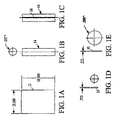
- Figures 1A-E are views of a known method of manufacturing a band for a CVT belt;
- Figure 2 is a side view of a method of manufacture and the resulting band for a CVT belt forming a first embodiment of the present invention; and
- Figure 3 is a side view of a method of manufacture and the resulting band for a CVT belt forming a second embodiment of the present invention.
-
- With reference to Figures 1A-E, a know method for manufacturing a
band 10 for a CVT belt will be described. As shown in Figure 1A, theband 10 begins as arectangular metal sheet 12. The sheet is then rolled into atube 14 as shown in Figure 1B. The tube is then laser welded or otherwise welded alongseam 16, as seen in Figure 1C.Individual bands 10 are then cut from thetube 14 to have a desired width, for example, 3/8 inch, as illustrated in Figure 1D. - The
bands 10 are then roll expanded to the final diameter and thickness, as illustrated in Figure 1E. As a specific example, therectangular sheet 12 may be eighteen inches long and about twelve inches wide. The thickness of the sheet may be about 0.017 inches (17 mils). The roll expanding will reduce the thickness of the bands to about 0.008 inches (8 mils). - With reference now to Figure 2, an improved method of manufacture and the resulting band thereof forming a first embodiment of the present invention will be described. The method is used to manufacture
bands 100 for use in a belt for a CVT transmission. However, the method and bands can be used for other applications if desired. - The
band 100 begins as a continuousthin metal strip 102 of the type readily available from steel manufacturers. Thethin strip 102 is spirally wound over amandrel 104, guided bysupport rollers 106 to form acontinuous tube 108. - The mandrel preferably has an outer diameter between 3-5 inches. The
seam 110 formed between abutting edges of thethin strip 102 as it is wound on themandrel 104 is welded bywelder 112, preferably a laser welder. As can be appreciated, as thethin strip 102 is wound about the mandrel, thecontinuous tube 108 grows in the direction away from the support rollers 106 (to the left in Figure 2). This movement is along theaxis 114 of thecontinuous tube 108. Acutting device 116 is then used to cut theindividual bands 100 off theend 118 of thecontinuous tube 108 spaced from thesupport rolls 106. Thecutting device 116 is preferably either a laser cutter or a mechanical slitting device. One ormore cutting devices 116 can be used, depending on the feed rate of thecontinuous tube 108 and the mounting and speed capabilities of thecutting device 116. Thecutting device 116 is mounted on a movingsupport 120 which moves in the direction ofaxis 114 at the same speed thecontinuous tube 108 grows in order to provide bands with edges perpendicular theaxis 114. It may also be desirable to have thecutting device 116 move radially about thecontinuous tube 108 to increase the speed of cutting and to balance the rate of operation of thecutting device 116 with the axial motion of the tube. - Subsequent to cutting the
bands 100, thebands 100 are typically roll expanded to the desired final diameter and thickness, deburred and heat treated. - As one actual process incorporating the teachings of the present invention, the
bands 100 after final forming may be approximately eight inches in diameter, .38 inch wide and have a thickness of 0.008 inches. Thethin strip 102 has a strip width of about 2.3 inches and the mandrel is about 4 inches in diameter. The thickness of the thin strip is about 0.017 inches. Themandrel 104 is rotated at a rate of about eight revolutions per minute (rpm). The angle of thethin strip 102 wound on the mandrel is about 30 degrees relative to theaxis 114. The movement of thecontinuous tube 108 alongaxis 114 is about 21 inches per minute. Thebands 100 are cut with the width of 3/8 inch, having 0.020 inches of cut-off Kerf. This specific operation is for purposes of example only, and the present invention can be applied to many different dimensions. - Advantages of the present invention include the fact that the operation is continuous, which results in a high quality of bands produced for one piece of manufacturing equipment with limited human labor required, translating into reduced manufacturing costs. High quality and consistency are associated with a continuous operation, which will be consistent over a long period of time for a large number of bands. Once the operation is set up, the winding and welding operation can run consistently, preferably virtually unattended.
- In particular, the prior art technique required each individual section of steel to be manually aligned for welding, which can be a significant cause of variation in the resulting weld strength. The present invention also eliminates the waste associated with end effects of the weld with the prior known technique. All the material fed into the operation of the present invention is utilized in the final band product, with the exception of a very small amount of material lost in the process of cutting the tube into individual bands. The spiral weld produces a welded joint that is at a more acute angle relative to the direction of load carried by the band than the 90 degree weld found in the known manufacturing technique. This results in more weld length to carry the tensile load in the band, and less sensitivity to any minute flaws in the weld. The thin strip raw material is in a form that is readily available, and is easy to handle compared to the known technique of using wide, rectangular sections of sheet metal.
- With reference to Figure 3, a second embodiment of the present invention will be described.
- Many of the steps and features of the second embodiment are identical to that described above with regard to the first embodiment and are identified by the same reference numerals. However, the
continuous tube 150 utilized in the second embodiment is roll expanded to a larger diameter in the tube form by aconical mandrel 152 and rolls 154. Thebands 156 cut from thecontinuous tube 150 by cuttingdevice 116 are thus near or at the final diameter of the band. This second embodiment requires high forces to roll a long length oftubing 150 to a larger diameter. However, if the forces are available, the manufacturing cost could be further reduced. - While certain embodiments of the apparatus and method of the present invention have been presented, it is appreciated that the invention is not limited thereto. Many variations, substitutions and amendments can be made to these embodiments without departing from the scope of the invention. Such variations, substitutions and amendments as would be apparent to one having ordinary skill in the art who will be familiar with the teachings disclosed herein are also deemed to fall within the scope and spirit of the present invention, as hereinafter claimed.
Claims (10)
- A method for manufacturing a band for a CVT belt including the steps of: spiral winding a thin strip (102) into a continuous tube (108,150);welding the thin strip along the spiral winding; andcutting bands (100,156) off of the continuous tube.
- The method of claim 1 wherein the step of cutting includes the step of laser cutting the bands (100,156).
- The method of claim 1 wherein the step of cutting the bands includes the step of mechanically slitting the bands (100,156).
- The method of claim 1 wherein the step of spiral winding the thin strip into a continuous tube includes the step of spiral winding thin strip over a mandrel (104,152).
- The method of claim 1 wherein the step of spiral winding thin strip into a continuous tube includes the step of spiral winding the thin strip against a plurality of feed rollers (106).
- The method of claim 1 wherein the step of cutting bands off of the continuous tube includes the steps of moving a band cutter (116) along the axis of the continuous tube at the same speed the continuous tube is formed.
- The method of claim 1 wherein the method further includes the step of expanding the continuous tube diameter prior to cutting bands off of the continuous tube.
- The method of claim 1 further comprising the step of expanding the bands cut off of the continuous tube.
- The band (100,156) formed by the method of claim 1.
- The method of claim 1 wherein said CVT belt includes a plurality of transverse members, each transverse member having at least one slot, at least one carrier received in said at least one slot of said transverse members, said carrier formed of a plurality of bands, said transverse elements being assembled along said carrier in an adjacent relationship.
Applications Claiming Priority (2)
| Application Number | Priority Date | Filing Date | Title |
|---|---|---|---|
| US09/464,656 US6497633B1 (en) | 1999-12-15 | 1999-12-15 | Continuous manufacture of push type CVT belt bands utilizing spiral winding & welding to form tube and slitting tube to form band of predetermined width |
| US464656 | 1999-12-15 |
Publications (1)
| Publication Number | Publication Date |
|---|---|
| EP1108919A1 true EP1108919A1 (en) | 2001-06-20 |
Family
ID=23844769
Family Applications (1)
| Application Number | Title | Priority Date | Filing Date |
|---|---|---|---|
| EP00310361A Withdrawn EP1108919A1 (en) | 1999-12-15 | 2000-11-22 | Continuous manufacture of push type CVT belt bands |
Country Status (3)
| Country | Link |
|---|---|
| US (1) | US6497633B1 (en) |
| EP (1) | EP1108919A1 (en) |
| JP (1) | JP2001212639A (en) |
Cited By (3)
| Publication number | Priority date | Publication date | Assignee | Title |
|---|---|---|---|---|
| NL1024614C2 (en) * | 2003-10-24 | 2005-04-27 | Bosch Gmbh Robert | Cutting process for manufacturing a ring, cutting device, ring and push belt provided with a ring. |
| AT512972A1 (en) * | 2012-06-04 | 2013-12-15 | Berndorf Band Gmbh | Endless belt with an annular band body |
| WO2015097296A1 (en) | 2013-12-24 | 2015-07-02 | Robert Bosch Gmbh | Method for manufacturing a carrier ring suitable for use in a drive belt for a continuously variable transmission |
Families Citing this family (10)
| Publication number | Priority date | Publication date | Assignee | Title |
|---|---|---|---|---|
| US7294077B2 (en) * | 2004-02-24 | 2007-11-13 | General Motors Corporation | CVT belt with chromium nitride coating |
| US20090294567A1 (en) * | 2008-05-30 | 2009-12-03 | General Electric Company | Spiral winding systems for manufacturing composite fan bypass ducts and other like components |
| US20090294566A1 (en) * | 2008-05-30 | 2009-12-03 | General Electric Company | Methods for spiral winding composite fan bypass ducts and other like components |
| AR072415A1 (en) * | 2008-07-02 | 2010-08-25 | Shell Int Research | A PROCESS FOR THE ELABORATION OF AN ELONGED TUBE |
| JP5519316B2 (en) * | 2010-02-16 | 2014-06-11 | 本田技研工業株式会社 | Cylindrical workpiece cutting device |
| JP5513923B2 (en) * | 2010-02-16 | 2014-06-04 | 本田技研工業株式会社 | Metal ring manufacturing method |
| CN103498975A (en) * | 2013-10-11 | 2014-01-08 | 昆山市华浦塑业有限公司 | Metal plastic composite tube and machining method thereof |
| US9782812B2 (en) * | 2014-03-26 | 2017-10-10 | Roderick Clarence Minch | Method and apparatus for cutting openings in sidewall of spiral pipe |
| JP6384086B2 (en) * | 2014-03-28 | 2018-09-05 | 愛知製鋼株式会社 | Metal ring manufacturing method |
| SI3197630T1 (en) * | 2015-03-19 | 2018-06-29 | Westfalia Metallschlauchtechnik Gmbh & Co. Kg | Apparatus for producing coiled tubes |
Citations (5)
| Publication number | Priority date | Publication date | Assignee | Title |
|---|---|---|---|---|
| JPS5886946A (en) * | 1981-11-20 | 1983-05-24 | Nissan Motor Co Ltd | Manufacture of transmission v-belt |
| EP0107218A1 (en) * | 1982-09-23 | 1984-05-02 | Van Doorne's Transmissie B.V. | Process for the manufacture of endless metal bands |
| JPS6163327A (en) * | 1984-09-06 | 1986-04-01 | Nhk Spring Co Ltd | Production of endless metal band for belt |
| US5127885A (en) * | 1990-12-24 | 1992-07-07 | Xerox Corporation | Endless metal belt with strengthened edges |
| JPH08170692A (en) * | 1994-12-19 | 1996-07-02 | Nippon Bell Parts Kk | Metal endless belt and manufacture thereof |
Family Cites Families (5)
| Publication number | Priority date | Publication date | Assignee | Title |
|---|---|---|---|---|
| US2233233A (en) * | 1939-02-02 | 1941-02-25 | Williams Ralph | Machine for helically coiling and welding strip metal to form continuous pipes |
| US3106177A (en) * | 1959-01-02 | 1963-10-08 | Raymond Int Inc | Tube forming method and apparatus |
| US3797088A (en) * | 1972-09-08 | 1974-03-19 | Grotnes Machine Works Inc | Method of manufacturing cylindrical blanks |
| NL8203934A (en) | 1982-10-12 | 1984-05-01 | Philips Nv | NUCLEAR SPIN COMMENT. |
| US4590652A (en) * | 1983-10-14 | 1986-05-27 | Apx Group Inc. | Method for fabricating an air gap pipe |
-
1999
- 1999-12-15 US US09/464,656 patent/US6497633B1/en not_active Expired - Fee Related
-
2000
- 2000-11-22 EP EP00310361A patent/EP1108919A1/en not_active Withdrawn
- 2000-12-15 JP JP2000381637A patent/JP2001212639A/en active Pending
Patent Citations (5)
| Publication number | Priority date | Publication date | Assignee | Title |
|---|---|---|---|---|
| JPS5886946A (en) * | 1981-11-20 | 1983-05-24 | Nissan Motor Co Ltd | Manufacture of transmission v-belt |
| EP0107218A1 (en) * | 1982-09-23 | 1984-05-02 | Van Doorne's Transmissie B.V. | Process for the manufacture of endless metal bands |
| JPS6163327A (en) * | 1984-09-06 | 1986-04-01 | Nhk Spring Co Ltd | Production of endless metal band for belt |
| US5127885A (en) * | 1990-12-24 | 1992-07-07 | Xerox Corporation | Endless metal belt with strengthened edges |
| JPH08170692A (en) * | 1994-12-19 | 1996-07-02 | Nippon Bell Parts Kk | Metal endless belt and manufacture thereof |
Non-Patent Citations (3)
| Title |
|---|
| PATENT ABSTRACTS OF JAPAN vol. 007, no. 187 (M - 236) 16 August 1983 (1983-08-16) * |
| PATENT ABSTRACTS OF JAPAN vol. 010, no. 227 (M - 505) 7 August 1986 (1986-08-07) * |
| PATENT ABSTRACTS OF JAPAN vol. 1996, no. 11 29 November 1996 (1996-11-29) * |
Cited By (6)
| Publication number | Priority date | Publication date | Assignee | Title |
|---|---|---|---|---|
| NL1024614C2 (en) * | 2003-10-24 | 2005-04-27 | Bosch Gmbh Robert | Cutting process for manufacturing a ring, cutting device, ring and push belt provided with a ring. |
| WO2005039812A1 (en) * | 2003-10-24 | 2005-05-06 | Robert Bosch Gmbh | Cutting process for the manufacture of a ring, cutting device, ring and push belt provided with the ring |
| CN100450682C (en) * | 2003-10-24 | 2009-01-14 | 罗伯特·博世有限公司 | Cutting method for producing ring, ring and push belt provided with ring |
| AT512972A1 (en) * | 2012-06-04 | 2013-12-15 | Berndorf Band Gmbh | Endless belt with an annular band body |
| AT512972B1 (en) * | 2012-06-04 | 2014-06-15 | Berndorf Band Gmbh | Endless belt with an annular band body |
| WO2015097296A1 (en) | 2013-12-24 | 2015-07-02 | Robert Bosch Gmbh | Method for manufacturing a carrier ring suitable for use in a drive belt for a continuously variable transmission |
Also Published As
| Publication number | Publication date |
|---|---|
| JP2001212639A (en) | 2001-08-07 |
| US6497633B1 (en) | 2002-12-24 |
Similar Documents
| Publication | Publication Date | Title |
|---|---|---|
| US6497633B1 (en) | Continuous manufacture of push type CVT belt bands utilizing spiral winding & welding to form tube and slitting tube to form band of predetermined width | |
| EP0014014B1 (en) | A composite driving belt, endless metal band for a driving belt and a method of processing such a band | |
| US4010831A (en) | Transmission friction plate and device | |
| MXPA04001015A (en) | Manufacturing process and apparatus for making a helical rib tube. | |
| WO1989005723A1 (en) | A pipe-forming machine | |
| JPH0852613A (en) | Method and device for cutting pipe | |
| JP2011513653A (en) | Multilayer corrugated tubular structure | |
| US5001819A (en) | Apparatus for forming perforated tubes | |
| EP0138745B1 (en) | Driving pulley for a slat conveyor | |
| US8578577B2 (en) | Machine to produce expanded metal spirally lock-seamed tubing from solid coil stock | |
| US7574886B2 (en) | Apparatus for producing helically corrugated metal pipe and related method | |
| US4058996A (en) | Machine for the manufacture of helically wound metal duct or pipe | |
| JP2003145221A (en) | Method for manufacturing longitudinally welded helically corrugated metal tubing | |
| CA2948392C (en) | Improved screw conveyors, augers, and flighting for use therein | |
| DE2228496C2 (en) | Process for corrugating a thin, flat sheet | |
| JPS6065946A (en) | Belt type stepless speed change gear | |
| JP5070900B2 (en) | Belt for continuously variable transmission and belt type continuously variable transmission | |
| SU1687330A1 (en) | Portable apparatus for tube beading | |
| PL179477B1 (en) | Method of and apparatus for making spiral coils of seamed tubes | |
| KR102206279B1 (en) | Apparatus and method for attaching friction material of synchronizer ring | |
| JPH0333050B2 (en) | ||
| MX2008008792A (en) | Method, and apparatus, for piercing and rolling seamless pipe. | |
| CN116458714B (en) | A hollow tube circle buckle chain production device | |
| CN101722422B (en) | Device for producing a coupling cage, in particular a double coupling, and bending device | |
| RU2165045C1 (en) | Method of manufacture of belt-type seal from expanded graphite and device for its embodiment |
Legal Events
| Date | Code | Title | Description |
|---|---|---|---|
| PUAI | Public reference made under article 153(3) epc to a published international application that has entered the european phase |
Free format text: ORIGINAL CODE: 0009012 |
|
| AK | Designated contracting states |
Kind code of ref document: A1 Designated state(s): DE ES FR GB IT SE |
|
| AX | Request for extension of the european patent |
Free format text: AL;LT;LV;MK;RO;SI |
|
| 17P | Request for examination filed |
Effective date: 20011210 |
|
| AKX | Designation fees paid |
Free format text: DE ES FR GB IT SE |
|
| 17Q | First examination report despatched |
Effective date: 20031113 |
|
| GRAP | Despatch of communication of intention to grant a patent |
Free format text: ORIGINAL CODE: EPIDOSNIGR1 |
|
| RAP1 | Party data changed (applicant data changed or rights of an application transferred) |
Owner name: BORGWARNER INC. |
|
| STAA | Information on the status of an ep patent application or granted ep patent |
Free format text: STATUS: THE APPLICATION IS DEEMED TO BE WITHDRAWN |
|
| 18D | Application deemed to be withdrawn |
Effective date: 20041214 |