EP1108901B1 - Abdichtungsbefestigungsvorrichtung - Google Patents
Abdichtungsbefestigungsvorrichtung Download PDFInfo
- Publication number
- EP1108901B1 EP1108901B1 EP00311266A EP00311266A EP1108901B1 EP 1108901 B1 EP1108901 B1 EP 1108901B1 EP 00311266 A EP00311266 A EP 00311266A EP 00311266 A EP00311266 A EP 00311266A EP 1108901 B1 EP1108901 B1 EP 1108901B1
- Authority
- EP
- European Patent Office
- Prior art keywords
- retainer
- annular
- central portion
- flange
- bore
- Prior art date
- Legal status (The legal status is an assumption and is not a legal conclusion. Google has not performed a legal analysis and makes no representation as to the accuracy of the status listed.)
- Expired - Lifetime
Links
- NJPPVKZQTLUDBO-UHFFFAOYSA-N novaluron Chemical compound C1=C(Cl)C(OC(F)(F)C(OC(F)(F)F)F)=CC=C1NC(=O)NC(=O)C1=C(F)C=CC=C1F NJPPVKZQTLUDBO-UHFFFAOYSA-N 0.000 claims description 17
- 125000006850 spacer group Chemical group 0.000 claims description 13
- 230000008602 contraction Effects 0.000 claims description 4
- 230000000717 retained effect Effects 0.000 claims description 4
- 239000007789 gas Substances 0.000 description 10
- 238000009434 installation Methods 0.000 description 5
- 230000000712 assembly Effects 0.000 description 4
- 238000000429 assembly Methods 0.000 description 4
- 238000005266 casting Methods 0.000 description 2
- 238000004519 manufacturing process Methods 0.000 description 2
- 239000000463 material Substances 0.000 description 2
- 238000003491 array Methods 0.000 description 1
- 238000005219 brazing Methods 0.000 description 1
- 238000010438 heat treatment Methods 0.000 description 1
- 238000003780 insertion Methods 0.000 description 1
- 230000037431 insertion Effects 0.000 description 1
- 238000003466 welding Methods 0.000 description 1
Images


Classifications
-
- F—MECHANICAL ENGINEERING; LIGHTING; HEATING; WEAPONS; BLASTING
- F01—MACHINES OR ENGINES IN GENERAL; ENGINE PLANTS IN GENERAL; STEAM ENGINES
- F01D—NON-POSITIVE DISPLACEMENT MACHINES OR ENGINES, e.g. STEAM TURBINES
- F01D25/00—Component parts, details, or accessories, not provided for in, or of interest apart from, other groups
- F01D25/24—Casings; Casing parts, e.g. diaphragms, casing fastenings
- F01D25/246—Fastening of diaphragms or stator-rings
-
- F—MECHANICAL ENGINEERING; LIGHTING; HEATING; WEAPONS; BLASTING
- F01—MACHINES OR ENGINES IN GENERAL; ENGINE PLANTS IN GENERAL; STEAM ENGINES
- F01D—NON-POSITIVE DISPLACEMENT MACHINES OR ENGINES, e.g. STEAM TURBINES
- F01D11/00—Preventing or minimising internal leakage of working-fluid, e.g. between stages
- F01D11/001—Preventing or minimising internal leakage of working-fluid, e.g. between stages for sealing space between stator blade and rotor
-
- F—MECHANICAL ENGINEERING; LIGHTING; HEATING; WEAPONS; BLASTING
- F04—POSITIVE - DISPLACEMENT MACHINES FOR LIQUIDS; PUMPS FOR LIQUIDS OR ELASTIC FLUIDS
- F04D—NON-POSITIVE-DISPLACEMENT PUMPS
- F04D29/00—Details, component parts, or accessories
- F04D29/08—Sealings
- F04D29/16—Sealings between pressure and suction sides
- F04D29/161—Sealings between pressure and suction sides especially adapted for elastic fluid pumps
- F04D29/164—Sealings between pressure and suction sides especially adapted for elastic fluid pumps of an axial flow wheel
-
- F—MECHANICAL ENGINEERING; LIGHTING; HEATING; WEAPONS; BLASTING
- F16—ENGINEERING ELEMENTS AND UNITS; GENERAL MEASURES FOR PRODUCING AND MAINTAINING EFFECTIVE FUNCTIONING OF MACHINES OR INSTALLATIONS; THERMAL INSULATION IN GENERAL
- F16B—DEVICES FOR FASTENING OR SECURING CONSTRUCTIONAL ELEMENTS OR MACHINE PARTS TOGETHER, e.g. NAILS, BOLTS, CIRCLIPS, CLAMPS, CLIPS OR WEDGES; JOINTS OR JOINTING
- F16B5/00—Joining sheets or plates, e.g. panels, to one another or to strips or bars parallel to them
- F16B5/02—Joining sheets or plates, e.g. panels, to one another or to strips or bars parallel to them by means of fastening members using screw-thread
- F16B5/0241—Joining sheets or plates, e.g. panels, to one another or to strips or bars parallel to them by means of fastening members using screw-thread with the possibility for the connection to absorb deformation, e.g. thermal or vibrational
Definitions
- This invention relates to a retainer and an assembly incorporating said retainer. It relates in particular to inter-stage seal retainers used in gas turbine engine assemblies and, more particularly, to inter-stage seal retainers and assemblies to mount inter-stage turbine seals to nozzles or vane assemblies of gas turbine engines.
- the seal assembly in the turbine is intended to be able to translate relative to a nozzle stage of the turbine and the retainer is used to maintain its mounting to the nozzle while allowing limited axial movement.
- FR 2,768,197 discloses a fixing plate for particular use in vehicle body work.
- a retainer comprising a body having a central portion through which a bore is formed around a bore axis, a central tab extending radially outwardly from said central portion with respect to said bore axis, first and second arms, respectively, extending in opposite respective first and second substantially radial directions, with respect to said bore axis, away from said central portion and each other,and perpendicularly to the tab, axial spacers extending from first and second free ends of said first and second arms respectively in a direction generally parallel to said bore axis, anti-rotation feet depending from said first and second free ends in an opposite direction from which said central tab extends, a pedestal assembly extending in the same direction as said axial spacers from said central portion and located further in this direction than the central tab, said pedestal assembly having at least two part-annular cylindrical inner surfaces circumscribed around said bore axis and at least two part-annular cylindrical outer surfaces, each part-annular cylindrical outer surface extending between generally parallel spaced apart first
- the present invention provides an assembly comprising an annular first ring having a perpendicular annular first flange extending radially outwardly from said first ring, an annular second ring having a perpendicular annular second flange extending radially inwardly from said second ring and to which said first flange is retained by a retainer as hereinbefore described, a plurality of circumferentially spaced slots formed in and extending through said first flange and located to generally align radially and circumferentially with holes in said second flange, said slots having straight slot edges extending lengthwise tangentially with respect to said first flange, a plurality of bolts, each including a bolt head and shank inserted through respective retainer bores, slots in said first annular ring and holes in said second annular ring to form the assembly secured by respective nuts engaging respective bolts at a bolt end opposite said bolt head; and said retainer operably associated with each of said slots and secured to said second flange to constrain
- the retainer may be an integrally cast unit including the body, the central portion, the central tab, the first and second arms, the axial spacers, the anti-rotation feet, and the pedestal assembly.
- the pedestal assembly may include first and second mirror image pedestals, respectively, extending aft from the central portion, and the first and second pedestals may be semi-annular in shape and may include the semi-annular cylindrical outer surface, and the cylindrical inner surface which is semi-annular and extends between the inner and outer flats.
- the anti-rotation feet may have rounded ends.
- the cylindrical inner surface may be substantially continuous with a bore surface inside of the bore.
- the central tab may be flush with a flat central aft facing surface of the central portion.
- the retainer may further comprise a counter-bore of the bore circumscribed about the bore axis.
- the first and second pedestals and the cylindrical inner and outer surfaces may be substantially normal and straight from the chamfers to the flat aft facing central surface of the central portion.
- the retainer may further comprise a fillet between each of the first and second pedestals between the first and second pedestals and the central portion along the cylindrical inner and outer surfaces and the flat aft facing central surface.
- the retainer may further comprise pedestal shank sections of constant cross-section extending between the chamfers and the fillets.
- the assembly may further comprise a counter-bore of the bore circumscribed about the bore axis and the bolt head sitting the counter-bore.
- the assembly may further comprise a fillet between each of the first and second pedestals between the first and second pedestals and the central portion along the cylindrical inner and outer surfaces and the flat aft facing central surface.
- the assembly may further comprise pedestal shank sections of constant cross-section extending between the chamfers and the fillets.
- the assembly may be a gas turbine engine inter-stage seal assembly further comprising an abradable shroud assembly having an abradable annular honeycomb seal member fixedly attached to the annular first ring, an annular nozzle stage having nozzle vanes attached to the annular second ring.
- the central portion may have a substantially constant first thickness that is axially thicker than a second thickness of the first and second arms.
- the second thickness may taper down as the first and second arms, respectively, extend outwardly in the first and second tangential directions away from the central portion.
- a retainer in an exemplary embodiment of the invention is used in a gas turbine engine inter-stage seal assembly to retain an annular seal ring flange of a seal ring against an annular platform flange extending radially inwardly from an inner platform of an annular nozzle stage having nozzle vanes.
- the present invention provides various improvements and advantages over the prior art.
- the chamfers on the pedestals and the axial location of central tab provide a combination of "fool proofing" and a better angle of installing the pedestals of the retainer in the slots of the seal flange.
- the shape of the pedestals together with the chamfers provide a more repeatable and accurate seating of the retainer and the pedestals disposed through the slots so as to prevent improper clamping which could cause the pedestals to fail.
- the rounded ends of the anti-rotation feet provide improved insertion of the pedestals in the slot and proper seating of the retainer as well as improved anti-torquing capabilities.
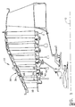
- FIG. 1 is a partial cutaway view of a highly simplified schematic illustration of an exemplary gas turbine engine low pressure turbine section 10 arranged substantially concentrically about an engine centerline 12 and aft of a high pressure turbine section 16.
- the low pressure turbine section 10 rotates the fan section of the engine (not shown) and other components through a rotor shaft 18.
- the turbine section 10 includes alternating annular arrays of nozzle vanes 26 and rotor blades 28, the vanes 26 and blades 28 being airfoils for reacting the hot gas stream.
- the nozzle vanes 26 are attached to a radially outer band 32 and a radially inner ring or platform 30 to form non-rotating annular nozzle stages 36.
- the nozzle stages are suitably attached to and supported by an annular outer engine casing 38.
- Each of the rotor blades 28 is attached at its radially inner end to periphery of a disk 40 which is attached to the rotor shaft 18.
- an inter-stage seal assembly 42 (shown in greater detail in FIG. 2) is used for reducing gas leakage around the nozzle stage 36.
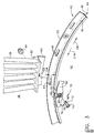
- the hot gases passing through the turbine section 10 heat the various components, such as the vanes 26 and blades 28, the bands 32, the platforms 30 and the disks 40 and cause them to thermally expand. Since the components may be made of diverse materials, may have diverse material thicknesses, and may be subject to diverse rates of heating, each component may expand differently.
- the seal assembly 42 is adapted to accommodate differential expansion in a radial direction and similar contraction as components cool.
- the seal assembly 42 includes a radially inner abradable shroud assembly 44 having an abradable annular honeycomb seal member 46 fixedly attached to an annular seal ring 48 by brazing, welding, or other suitable means well known in the art.
- the seal ring 48 includes an annular seal ring flange 50 for mounting the abradable shroud assembly 44 to an annular platform flange 60 extending radially inwardly from the inner platform 30 of the nozzle vane 26.
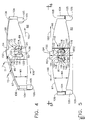
- the seal assembly 42 is mounted and secured to the annular platform flange 60 by a bolt assembly 70 as illustrated in exploded view in FIG. 3.
- a plurality of circumferentially spaced slots 64 formed in and extending through the annular seal ring flange 50 are located to generally align radially and circumferentially with holes 68 in the annular platform flange 60.
- the slots 64 have straight slot edges 66 extending lengthwise tangentially with respect to the annular seal ring flange 50 and slot widths SW between the slot edges.
- the bolt assembly 70 includes a bolt 72 having a socket type bolt head 74 and a shank 76 with unthreaded and threaded shank portions 78 and 80, respectively and a nut 84 which threads onto the threaded shank portion 80.
- the bolt 72 is designed to be held with a loose fit in an inter-stage seal retainer 82 during assembly and disassembly of the seal assembly 42 to the annular platform flange 60 of the inner platform 30.
- the bolt head 74 sits in a counter-bore 86 of a bore 88 having a bore axis 89 in the inter-stage seal retainer 82.
- the inter-stage seal retainer 82 cooperates with the slots 64 to constrain seal assembly 42, while permitting differential radial expansion and contraction between the seal assembly 42 and the inner platform 30.
- the retainer 82 includes a body 90 with a central portion 92 through which the counter-bore 86 and the bore 88 are formed.
- the central portion 92 has square flat forward and aft facing central surfaces 95 and 96, respectively, with the counter-bore 86 extending aft from the forward facing central surface 95.
- a central tab 94 extends radially outwardly from the central portion 92 and is flush with the flat central aft facing surface 96 of the central portion 92.
- Mirror image first and second arms 97 and 98, respectively, extend in opposite respective first and second tangential directions 100 and 102, with respect to the bore axis 89, away from the central portion 92 and each other.
- Axial spacers 104 extend aftwardly from first and second free ends 106 and 108 of the first and second arms 97 and 98, respectively.
- Anti-rotation feet 105 with rounded ends 109 depend or extend radially inwardly, with respect to the engine centerline 12, from the first and second free ends 106 and 108 of the first and second arms 97 and 98, respectively.
- the central portion 92 has a substantially constant first thickness T1 and is axially thicker than the first and second arms 97 and 98, respectively, which have a second thickness T2 that is less than first thickness T1.
- the second thickness T2 tapers down as the first and second arms 97 and 98, respectively, extend outwardly in the first and second tangential directions 100 and 102 away from the central portion 92.
- an arm width WA tapers curvedly down as the first and second arms 97 and 98, respectively, extend outwardly in the first and second tangential directions 100 and 102 away from the central portion 92.
- the first and second arms 97 and 98 are axially offset with respect to the central portion 92 and are located closer to the axial position of the aft facing central surface 96 than the axial position of the forward facing central surface 95 of the central portion 92.
- Each of the first and second pedestals 111 and 112 are semi-annular in shape with semi-annular cylindrical inner and outer surfaces 114 and 116, respectively.
- the semi-annular cylindrical inner surfaces 114 are circumscribed around the bore axis 89 and extend between generally parallel spaced apart radially inner and outer flat surfaces with respect to the bore axis 89, referred to hereinafter as radially inner and outer flats 120 and 122, respectively.
- the semi-annular cylindrical outer surfaces 116 of the first and second pedestals 111 and 112 are circumscribed around first and second offset axes 118 and 119 by a first radius R1 and a second radius R2, respectively, and extend between the inner and outer flats 120 and 122, respectively.
- the first offset axis 118 and the second offset axis 119 are offset a small distance from and on opposite sides of the bore axis 89.
- the radially inner flats 120 on the first and second pedestals 111 and 112 are coplanar and the radially outer flats 122 on the first and second pedestals 111 and 112 are coplanar.
- Axially outer ends 130, with respect to the bore axis 89, of the first and second pedestals 111 and 112 have chamfers 132 along the radially inner and outer flats 120 and 122, respectively.
- the semi-annular cylindrical inner surfaces 114 are substantially continuous with a bore surface 138 inside of the bore 88.
- the first and second pedestals 111 and 112 and their respective cylindrical inner and outer surfaces 114 and 116 are substantially normal and straight from the chamfers 132 to the flat aft facing central surface 96 of the central portion 92.
- the outer ends 130 of the first and second pedestals 111 and 112 have flat pedestal end surfaces 144 that are substantially parallel to the flat central aft facing surface 96 of the central portion 92.
- the flat pedestal end surfaces 144 are designed to seat flat against the annular platform flange 60 to which it is mounted and secured by the bolt assembly 70 as shown in FIGS. 2 and 7. This traps and retains the seal ring 48 by way of the seal ring flange 50 between the axial spacers 104 that extend aftwardly from the first and second free ends 106 and 108 of the first and second arms 97 and 98 of the retainer 82 and the platform flange 60 extending radially inwardly from the inner platform 30 of the nozzle vane 26.
- the plurality of circumferentially spaced slots 64 formed in and extending through the annular seal ring flange 50 are located to generally align radially and circumferentially with the holes 68 in the annular platform flange 60.
- the central tab 94 has a radially outer tab end 150 spaced a first radial distance RD1 away from the bore axis 89.
- the rounded ends 109 of the anti-rotation feet 105 extend radially inward to a second radial distance RD2 away from the bore axis 89.
- First and second radial distances RD1 and RD2 are unequal and are substantially the same distances from a radially inwardly facing annular platform surface 151 of the radially inner platform 30 and a radially outwardly facing annular platform surface 152 of the annular seal ring 48.
- the first radial distance RD1 is greater than a third radial distance RD3 between the bore axis 89 and the central portion 92 through which the counter-bore 86 is formed.
- the anti-rotation feet 105 to restrict rotation of the retainer relative to the annular seal ring 48 to no more than about a couple of degrees, approximately 2.3o in the exemplary embodiment, about the bore axis 89 in either the clockwise CW or counterclockwise CCW directions. This is accomplished by either of the anti-rotation feet 105 contacting the seal ring 48.
- the rounded ends 109 of the anti-rotation feet 105 allows restriction of rotation of the retainer 82 with a minimal amount of contact with the ring and thus reduces retainer interference with axial and circumferential restrained movement between the seal ring 48 and the annular platform flange 60 during engine operation.
- the rounded ends 105 also minimizes interference of the retainer 82 and the seal ring 48 during installation of the retainer and during torquing of the bolt 72.
- the chamfers 132 are an inclined plane relative to the seal slot edges 66 and during final assembly and torquing of the bolt and nut, the bolt clamp load causes the retainer to rotate and align with the straight slot edges 66.
- the invention provides full and proper seating of the retainer 82 on the annular platform flange 60 of the nozzle vane 26 and the pedestal assembly 110 and the pedestals 111 and 112 on the slot 64 on the platform flange.
- the chamfers 132 guide the pedestals 111 and 112 of the pedestal assembly 110 and the retainer 82 into the slot 64 in seal ring flange 50.
- the features of the present invention enable the retainer 82 to be aligned with the seal slot 64 regardless of the looseness of the subassembly joint between the seal assembly 42 and the platform flange 60 of the vane 26.
- the retainer 82 is an integrally cast unit, including the body 90, the central portion 92, the central tab 94, the first and second arms 97 and 98, axial spacers 104, anti-rotation feet 105, and the pedestal assembly 110 including the first and second pedestals 111 and 112.
- the integral casting of the retainer 82 improves repeatability and thus improves production of the retainer and reliability and ease of assembly of the retainer and the inter-stage seal assembly 42.
- the integral casting reduces production costs and improves dimensional control and accuracy of the retainer and the inter-stage seal assembly 42.
Landscapes
- Engineering & Computer Science (AREA)
- General Engineering & Computer Science (AREA)
- Mechanical Engineering (AREA)
- Turbine Rotor Nozzle Sealing (AREA)
- Gasket Seals (AREA)
Claims (10)
- Haltevorrichtung (82), aufweisend:einen Körper (90) mit einem mittigen Abschnitt (92), durch welchen eine Bohrung (88) um eine Bohrungsachse (89) herum ausgebildet ist;eine mittige Zunge (94), die sich radial von dem mittigen Abschnitt (92) in Bezug auf die Bohrungsachse (89) nach außen erstreckt;erste und zweite Arme (97 und 98), die sich jeweils in entgegengesetzte entsprechende erste und zweite im Wesentlichen radiale Richtungen (100 und 102) in Bezug auf die Bohrungsachse (89) von dem mittigen Abschnitt (92) und voneinander und senkrecht zu der Zunge (94) erstrecken,axiale Abstandshalter (104), die sich von ersten und zweiten freien Enden (106 und 108) der ersten bzw. zweiten Arme (97 und 98) jeweils in einer Richtung im Allgemeinen parallel zu der Bohrungsachse erstrecken,drehungsverhindernde Füße (105), die sich von den ersten und zweiten freien Enden (106 und 108) in einer entgegengesetzten Richtung zu der, aus welcher sich die mittige Zunge (94) erstreckt, erstrecken,eine Sockelanordnung (110), die sich in derselben Richtung wie die axialen Abstandshalter aus dem mittigen Abschnitt (92) erstreckt und in dieser Richtung weiter als die mittige Zunge verlaufend angeordnet ist,wobei die Sockelanordnung (110) wenigstens zwei der Bohrungsachse (89) umschriebene zylindrische Teilringinnenflächen (114) und wenigstens zwei zylindrische Teilringaußenflächen (116) aufweist,wobei sich jede zylindrische Teilringaußenfläche (116) zwischen im Allgemeinen parallelen, voneinander beabstandeten ersten und zweiten Abflachungen (120 und 122), eine auf jeder Seite einer die Bohrungsachse (89) und die Erstreckungsrichtungen der Arme (97 und 98) enthaltenden Ebene erstreckt, undwobei die ersten Abflachungen (120) komplanar sind, und die zweiten Abflachungen (122) koplanar sind, und mitAbschrägungen (132) entlang den ersten und zweiten Abflachungen (120 und 122).
- Haltevorrichtung (82) nach Anspruch 1, wobei die Haltevorrichtung (82) eine in einem Stück mit dem Körper (90), dem mittigen Abschnitt (92), der mittigen zunge (94), den ersten und zweiten Armen (97 und 98), den axialen Abstandhaltern (104), den Drehverhinderungsfüßen (105) und der Sockelanordnung (110) gegossene Einheit ist.
- Haltevorrichtung (82) nach Anspruch 1 oder 2, wobei die Sockelanordnung (110) erste und zweite spiegelbildliche Sockel (111 und 112) enthält, die sich in derselben Richtung wie die axialen Abstandshalter aus dem mittigen Abschnitt (92) erstrecken, und wobei die ersten und zweiten Sockel (111 und 112) eine Teilringform aufweisen und eine zylindrische Teilringaußenfläche (116) und die zylindrische Teilringinnenfläche (114) enthalten, welche sich zwischen den ersten und zweiten Abflachungen (120 und 122) erstreckt.
- Haltevorrichtung (82) nach Anspruch 1, 2 oder 3, wobei die Drehverhinderungsfüße (105) abgerundete Enden (109) haben.
- Haltevorrichtung (82) nach jedem vorstehenden Anspruch, wobei die zylindrischen Innenflächen (114) im Wesentlichen mit einer Bohrungsfläche (138) in der Bohrung (88) zusammenhängen.
- Haltevorrichtung (82) nach jedem vorstehenden Anspruch, wobei die mittige Zunge (94) bündig mit einer ebenen mittigen Fläche (96) des mittigen Abschnittes (92) ist, welche in dieselbe Richtung wie die Ausdehnung der axialen Abstandshalter weist.
- Haltevorrichtung (82) nach jedem vorstehenden Anspruch, welche ferner eine der Bohrung (88) umschriebene Senkbohrung (86) um die Bohrungsachse (89) herum aufweist.
- Haltevorrichtung (82) nach einem der vorstehenden Ansprüche 3 oder 6, wobei die ersten und zweiten Sockel (111 und 112), und die zylindrischen Innen- und Außenflächen (114 und 116) im Wesentlichen senkrecht und gerade von den Abschrägungen (132) zu der ebenen mittigen Fläche (96) des mittigen Abschnittes (92) verlaufen, welcher in dieselbe Richtung wie der Ausdehnung der mittigen Abstandshalter weist.
- Haltevorrichtung (82) nach Anspruch 8, welche ferner einen Übergang (140) zwischen jedem von den ersten und zweiten Sockeln (111 und 112) und den mittigen Abschnitt (92) entlang den Innen- und Außenflächen (114 und 116) und der ebenen mittigen Fläche (96) aufweist, welche in dieselbe Richtung wie die Ausdehnung der axialen Abstandshalter weist.
- Anordnung (42) aufweisend:einen ringförmigen ersten Ring (48) mit einem senkrechten ringförmigen ersten Flansch (50), der sich radial aus dem ersten Ring (48) heraus erstreckt,einen ringförmigen zweiten Ring (30) mit einem senkrechten ringförmigen zweiten Flansch (60), der sich von dem zweiten Ring (30) radial nach innen erstreckt und an welchem der erste Flansch (50) durch eine Haltevorrichtung (82) gemäß Beanspruchung in jedem der vorstehenden Ansprüche festgehalten wird,mehrere um den Umfang herum in Abstand angeordnete Schlitze (64), die in den ersten Flansch (50) ausgebildet sich und sich darin erstrecken und so angeordnet sind, dass sie radial und in Umfangsrichtung zu Löchern (68) in dem zweiten Flansch (60) ausgerichtet sind,wobei die Schlitze (64) gerade Schlitzkanten (66) aufweisen, die sich in Längsrichtung tangential in Bezug auf den ersten Flansch (50) erstrecken,mehrere Schrauben (72), welche jeweils einen Schraubenkopf (74) und einen Schaft (76) enthalten, der durch entsprechende Halterungsvorrichtungsbohrungen (88), Schlitze (64) in dem ersten Kreisring (42) und Löcher (68) in dem zweiten Kreisring (30) eingeführt ist, um die Anordnung auszubilden, die durch entsprechende Muttern (84) befestigt ist, die mit den entsprechenden Schrauben an einem dem Schraubenkopf gegenüberliegenden Schraubenende in Eingriff stehen; undwobei die Halterungsvorrichtung (82) funktionell jedem von den Schlitzen (64) zugeordnet und an dem zweiten Flansch (60) befestigt ist, um eine Umfangsdrehung des ersten Flansches (50) zu begrenzen, während gleichzeitig eine unterschiedliche radiale Ausdehnung und zusammenziehung zwischen den ersten und zweiten Flanschen (50) und (60) zugelassen wird.
Applications Claiming Priority (2)
| Application Number | Priority Date | Filing Date | Title |
|---|---|---|---|
| US09/466,554 US6220815B1 (en) | 1999-12-17 | 1999-12-17 | Inter-stage seal retainer and assembly |
| US466554 | 1999-12-17 |
Publications (3)
| Publication Number | Publication Date |
|---|---|
| EP1108901A2 EP1108901A2 (de) | 2001-06-20 |
| EP1108901A3 EP1108901A3 (de) | 2002-07-17 |
| EP1108901B1 true EP1108901B1 (de) | 2006-05-24 |
Family
ID=23852207
Family Applications (1)
| Application Number | Title | Priority Date | Filing Date |
|---|---|---|---|
| EP00311266A Expired - Lifetime EP1108901B1 (de) | 1999-12-17 | 2000-12-15 | Abdichtungsbefestigungsvorrichtung |
Country Status (6)
| Country | Link |
|---|---|
| US (1) | US6220815B1 (de) |
| EP (1) | EP1108901B1 (de) |
| JP (1) | JP4612946B2 (de) |
| BR (1) | BR0005898A (de) |
| CA (1) | CA2327817C (de) |
| DE (1) | DE60028170T2 (de) |
Cited By (1)
| Publication number | Priority date | Publication date | Assignee | Title |
|---|---|---|---|---|
| US9045984B2 (en) | 2012-05-31 | 2015-06-02 | United Technologies Corporation | Stator vane mistake proofing |
Families Citing this family (27)
| Publication number | Priority date | Publication date | Assignee | Title |
|---|---|---|---|---|
| DE10019440A1 (de) * | 2000-04-19 | 2001-10-25 | Rolls Royce Deutschland | Zwischenstufendichtungsträger |
| US6579065B2 (en) | 2001-09-13 | 2003-06-17 | General Electric Co. | Methods and apparatus for limiting fluid flow between adjacent rotor blades |
| US20080061515A1 (en) * | 2006-09-08 | 2008-03-13 | Eric Durocher | Rim seal for a gas turbine engine |
| US8950069B2 (en) * | 2006-12-29 | 2015-02-10 | Rolls-Royce North American Technologies, Inc. | Integrated compressor vane casing |
| US20090110548A1 (en) * | 2007-10-30 | 2009-04-30 | Pratt & Whitney Canada Corp. | Abradable rim seal for low pressure turbine stage |
| US8177492B2 (en) * | 2008-03-04 | 2012-05-15 | United Technologies Corporation | Passage obstruction for improved inlet coolant filling |
| FR2930592B1 (fr) * | 2008-04-24 | 2010-04-30 | Snecma | Distributeur de turbine pour une turbomachine |
| US9822649B2 (en) * | 2008-11-12 | 2017-11-21 | General Electric Company | Integrated combustor and stage 1 nozzle in a gas turbine and method |
| US9228446B2 (en) * | 2009-10-27 | 2016-01-05 | Gkn Aerospace Sweden Ab | Gas turbine engine component |
| US8382432B2 (en) * | 2010-03-08 | 2013-02-26 | General Electric Company | Cooled turbine rim seal |
| US8534673B2 (en) | 2010-08-20 | 2013-09-17 | Mitsubishi Power Systems Americas, Inc. | Inter stage seal housing having a replaceable wear strip |
| US8596969B2 (en) * | 2010-12-22 | 2013-12-03 | United Technologies Corporation | Axial retention feature for gas turbine engine vanes |
| US20130156584A1 (en) * | 2011-12-16 | 2013-06-20 | Carney R. Anderson | Compressor rotor with internal stiffening ring of distinct material |
| US9145786B2 (en) | 2012-04-17 | 2015-09-29 | General Electric Company | Method and apparatus for turbine clearance flow reduction |
| US9631517B2 (en) | 2012-12-29 | 2017-04-25 | United Technologies Corporation | Multi-piece fairing for monolithic turbine exhaust case |
| US11073044B2 (en) * | 2013-01-21 | 2021-07-27 | Raytheon Technologies Corporation | Adjustable floating oil channel for gas turbine engine gear drive |
| EP2818643B1 (de) * | 2013-06-27 | 2018-08-08 | MTU Aero Engines GmbH | Dichteinrichtung und Strömungsmaschine |
| US9816387B2 (en) | 2014-09-09 | 2017-11-14 | United Technologies Corporation | Attachment faces for clamped turbine stator of a gas turbine engine |
| US10598024B2 (en) | 2014-10-16 | 2020-03-24 | United Technologies Corporation | Tandem rotor blades |
| US10202857B2 (en) * | 2015-02-06 | 2019-02-12 | United Technologies Corporation | Vane stages |
| US9777593B2 (en) | 2015-02-23 | 2017-10-03 | General Electric Company | Hybrid metal and composite spool for rotating machinery |
| DE102016222608A1 (de) | 2016-11-17 | 2018-05-17 | MTU Aero Engines AG | Dichtungsanordnung für eine Leitschaufelanordnung einer Gasturbine |
| US10633992B2 (en) | 2017-03-08 | 2020-04-28 | Pratt & Whitney Canada Corp. | Rim seal |
| FR3068385B1 (fr) * | 2017-06-28 | 2021-08-06 | Safran Aircraft Engines | Ailette amovible pour un element annulaire aubage de turbomachine |
| US10539035B2 (en) | 2017-06-29 | 2020-01-21 | General Electric Company | Compliant rotatable inter-stage turbine seal |
| FR3091311B1 (fr) * | 2018-12-31 | 2021-04-09 | Safran Aircraft Engines | Distributeur pour turbine, turbine de turbomachine équipée de ce distributeur et turbomachine équipée de cette turbine. |
| DE102020200073A1 (de) * | 2020-01-07 | 2021-07-08 | Siemens Aktiengesellschaft | Leitschaufelkranz |
Family Cites Families (7)
| Publication number | Priority date | Publication date | Assignee | Title |
|---|---|---|---|---|
| US4767267A (en) | 1986-12-03 | 1988-08-30 | General Electric Company | Seal assembly |
| CA2070511C (en) | 1991-07-22 | 2001-08-21 | Steven Milo Toborg | Turbine nozzle support |
| US5211541A (en) | 1991-12-23 | 1993-05-18 | General Electric Company | Turbine support assembly including turbine heat shield and bolt retainer assembly |
| EP0626036B1 (de) * | 1992-02-10 | 1996-10-09 | United Technologies Corporation | Ejektor für kühlfluid |
| US5921749A (en) * | 1996-10-22 | 1999-07-13 | Siemens Westinghouse Power Corporation | Vane segment support and alignment device |
| US5848874A (en) * | 1997-05-13 | 1998-12-15 | United Technologies Corporation | Gas turbine stator vane assembly |
| FR2768197B1 (fr) * | 1997-09-05 | 1999-10-29 | Renault | Fixation auto-liberante au serrage, notamment pour une aile plastique d'un vehicule automobile |
-
1999
- 1999-12-17 US US09/466,554 patent/US6220815B1/en not_active Expired - Lifetime
-
2000
- 2000-12-07 CA CA002327817A patent/CA2327817C/en not_active Expired - Fee Related
- 2000-12-15 BR BR0005898-0A patent/BR0005898A/pt not_active IP Right Cessation
- 2000-12-15 JP JP2000381142A patent/JP4612946B2/ja not_active Expired - Fee Related
- 2000-12-15 DE DE60028170T patent/DE60028170T2/de not_active Expired - Lifetime
- 2000-12-15 EP EP00311266A patent/EP1108901B1/de not_active Expired - Lifetime
Cited By (1)
| Publication number | Priority date | Publication date | Assignee | Title |
|---|---|---|---|---|
| US9045984B2 (en) | 2012-05-31 | 2015-06-02 | United Technologies Corporation | Stator vane mistake proofing |
Also Published As
| Publication number | Publication date |
|---|---|
| EP1108901A2 (de) | 2001-06-20 |
| JP2001280101A (ja) | 2001-10-10 |
| CA2327817C (en) | 2007-02-06 |
| BR0005898A (pt) | 2001-07-17 |
| JP4612946B2 (ja) | 2011-01-12 |
| DE60028170D1 (de) | 2006-06-29 |
| DE60028170T2 (de) | 2007-05-03 |
| CA2327817A1 (en) | 2001-06-17 |
| EP1108901A3 (de) | 2002-07-17 |
| US6220815B1 (en) | 2001-04-24 |
Similar Documents
| Publication | Publication Date | Title |
|---|---|---|
| EP1108901B1 (de) | Abdichtungsbefestigungsvorrichtung | |
| US5441385A (en) | Turbine nozzle/nozzle support structure | |
| EP2154335B1 (de) | Ringdichtungsbefestigungssystem | |
| US5333995A (en) | Wear shim for a turbine engine | |
| EP2192275B1 (de) | Gasturbinenmotor | |
| CA2672323C (en) | Mid turbine frame system for gas turbine engine | |
| CA2686658C (en) | Mid turbine frame system for gas turbine engine | |
| EP2192276B1 (de) | Gasturbine umfassend Lagerträgerstruktur | |
| US6733233B2 (en) | Attachment of a ceramic shroud in a metal housing | |
| JP6141871B2 (ja) | 高温気体膨張装置の入口ケーシング組立体及び方法 | |
| US20050241290A1 (en) | Turbofan engine with the fan fixed to a drive shaft supported by a first and a second bearing | |
| US6821084B2 (en) | Torque tube bearing assembly | |
| EP1548238B1 (de) | Verfahren zur Optimierung von Radialspalten eines Gehäuses eines Turbinentriebwerks | |
| US6682307B1 (en) | Sealing system for a rotor of a turbo engine | |
| EP1054137B1 (de) | Aufhängung eines Innengehäuses in einem äusseren Turbinengehäuse | |
| US10006355B2 (en) | Variable-geometry exhaust turbine | |
| US8226357B2 (en) | Pitch control ring for stator vanes of a turbomachine | |
| JP2004084667A (ja) | ターボ加給機及びそのベーン支持リング | |
| EP1793095A1 (de) | Apparat zum Zusammenbauen eines Gasturbinentriebwerks | |
| US6209198B1 (en) | Method of assembling a variable stator vane assembly | |
| JPH04234504A (ja) | ガスタービンにおける羽根セグメントの支持装置 | |
| JP2002519564A (ja) | ターボ機械ロータ | |
| US7497658B2 (en) | Stacked reaction steam turbine stator assembly | |
| US10844745B2 (en) | Bearing assembly | |
| EP0716267A2 (de) | Brennkammerbauweise |
Legal Events
| Date | Code | Title | Description |
|---|---|---|---|
| PUAI | Public reference made under article 153(3) epc to a published international application that has entered the european phase |
Free format text: ORIGINAL CODE: 0009012 |
|
| AK | Designated contracting states |
Kind code of ref document: A2 Designated state(s): AT BE CH CY DE DK ES FI FR GB GR IE IT LI LU MC NL PT SE TR |
|
| AX | Request for extension of the european patent |
Free format text: AL;LT;LV;MK;RO;SI |
|
| PUAL | Search report despatched |
Free format text: ORIGINAL CODE: 0009013 |
|
| AK | Designated contracting states |
Kind code of ref document: A3 Designated state(s): AT BE CH CY DE DK ES FI FR GB GR IE IT LI LU MC NL PT SE TR |
|
| AX | Request for extension of the european patent |
Free format text: AL;LT;LV;MK;RO;SI |
|
| RIC1 | Information provided on ipc code assigned before grant |
Free format text: 7F 16B 37/08 A, 7F 16B 5/02 B |
|
| 17P | Request for examination filed |
Effective date: 20030117 |
|
| AKX | Designation fees paid |
Designated state(s): DE FR GB IT |
|
| 17Q | First examination report despatched |
Effective date: 20040227 |
|
| GRAP | Despatch of communication of intention to grant a patent |
Free format text: ORIGINAL CODE: EPIDOSNIGR1 |
|
| GRAS | Grant fee paid |
Free format text: ORIGINAL CODE: EPIDOSNIGR3 |
|
| GRAA | (expected) grant |
Free format text: ORIGINAL CODE: 0009210 |
|
| AK | Designated contracting states |
Kind code of ref document: B1 Designated state(s): DE FR GB IT |
|
| REG | Reference to a national code |
Ref country code: GB Ref legal event code: FG4D |
|
| REF | Corresponds to: |
Ref document number: 60028170 Country of ref document: DE Date of ref document: 20060629 Kind code of ref document: P |
|
| ET | Fr: translation filed | ||
| PLBE | No opposition filed within time limit |
Free format text: ORIGINAL CODE: 0009261 |
|
| STAA | Information on the status of an ep patent application or granted ep patent |
Free format text: STATUS: NO OPPOSITION FILED WITHIN TIME LIMIT |
|
| 26N | No opposition filed |
Effective date: 20070227 |
|
| REG | Reference to a national code |
Ref country code: FR Ref legal event code: PLFP Year of fee payment: 16 |
|
| PGFP | Annual fee paid to national office [announced via postgrant information from national office to epo] |
Ref country code: GB Payment date: 20151229 Year of fee payment: 16 |
|
| PGFP | Annual fee paid to national office [announced via postgrant information from national office to epo] |
Ref country code: FR Payment date: 20151217 Year of fee payment: 16 |
|
| PGFP | Annual fee paid to national office [announced via postgrant information from national office to epo] |
Ref country code: DE Payment date: 20151229 Year of fee payment: 16 |
|
| PG25 | Lapsed in a contracting state [announced via postgrant information from national office to epo] |
Ref country code: IT Free format text: LAPSE BECAUSE OF NON-PAYMENT OF DUE FEES Effective date: 20151215 |
|
| REG | Reference to a national code |
Ref country code: DE Ref legal event code: R119 Ref document number: 60028170 Country of ref document: DE |
|
| GBPC | Gb: european patent ceased through non-payment of renewal fee |
Effective date: 20161215 |
|
| PG25 | Lapsed in a contracting state [announced via postgrant information from national office to epo] |
Ref country code: IT Free format text: LAPSE BECAUSE OF NON-PAYMENT OF DUE FEES Effective date: 20151215 |
|
| PGFP | Annual fee paid to national office [announced via postgrant information from national office to epo] |
Ref country code: IT Payment date: 20151222 Year of fee payment: 16 |
|
| PGRI | Patent reinstated in contracting state [announced from national office to epo] |
Ref country code: IT Effective date: 20170710 |
|
| REG | Reference to a national code |
Ref country code: FR Ref legal event code: ST Effective date: 20170831 |
|
| PG25 | Lapsed in a contracting state [announced via postgrant information from national office to epo] |
Ref country code: IT Free format text: LAPSE BECAUSE OF NON-PAYMENT OF DUE FEES Effective date: 20161215 Ref country code: FR Free format text: LAPSE BECAUSE OF NON-PAYMENT OF DUE FEES Effective date: 20170102 |
|
| PGRI | Patent reinstated in contracting state [announced from national office to epo] |
Ref country code: IT Effective date: 20170710 |
|
| PG25 | Lapsed in a contracting state [announced via postgrant information from national office to epo] |
Ref country code: DE Free format text: LAPSE BECAUSE OF NON-PAYMENT OF DUE FEES Effective date: 20170701 Ref country code: GB Free format text: LAPSE BECAUSE OF NON-PAYMENT OF DUE FEES Effective date: 20161215 |