EP1108687A1 - Method and apparatus for testing dual-stage blowheads - Google Patents
Method and apparatus for testing dual-stage blowheads Download PDFInfo
- Publication number
- EP1108687A1 EP1108687A1 EP00127592A EP00127592A EP1108687A1 EP 1108687 A1 EP1108687 A1 EP 1108687A1 EP 00127592 A EP00127592 A EP 00127592A EP 00127592 A EP00127592 A EP 00127592A EP 1108687 A1 EP1108687 A1 EP 1108687A1
- Authority
- EP
- European Patent Office
- Prior art keywords
- blowhead
- air
- block
- passage means
- inlet
- Prior art date
- Legal status (The legal status is an assumption and is not a legal conclusion. Google has not performed a legal analysis and makes no representation as to the accuracy of the status listed.)
- Withdrawn
Links
- 238000012360 testing method Methods 0.000 title claims abstract description 40
- 238000000034 method Methods 0.000 title claims description 11
- 238000001816 cooling Methods 0.000 claims abstract description 26
- 230000006835 compression Effects 0.000 claims description 2
- 238000007906 compression Methods 0.000 claims description 2
- 230000009977 dual effect Effects 0.000 claims 3
- 238000003780 insertion Methods 0.000 claims 1
- 230000037431 insertion Effects 0.000 claims 1
- 230000001105 regulatory effect Effects 0.000 claims 1
- 238000010998 test method Methods 0.000 claims 1
- 238000004519 manufacturing process Methods 0.000 description 5
- 238000012986 modification Methods 0.000 description 4
- 230000004048 modification Effects 0.000 description 4
- 238000007664 blowing Methods 0.000 description 3
- 239000006060 molten glass Substances 0.000 description 3
- 241000272168 Laridae Species 0.000 description 1
- 230000006978 adaptation Effects 0.000 description 1
- 238000010586 diagram Methods 0.000 description 1
- 239000011521 glass Substances 0.000 description 1
- 238000005259 measurement Methods 0.000 description 1
- 230000002093 peripheral effect Effects 0.000 description 1
- 238000003825 pressing Methods 0.000 description 1
Images


Classifications
-
- C—CHEMISTRY; METALLURGY
- C03—GLASS; MINERAL OR SLAG WOOL
- C03B—MANUFACTURE, SHAPING, OR SUPPLEMENTARY PROCESSES
- C03B9/00—Blowing glass; Production of hollow glass articles
- C03B9/30—Details of blowing glass; Use of materials for the moulds
- C03B9/38—Means for cooling, heating, or insulating glass-blowing machines or for cooling the glass moulded by the machine
- C03B9/3841—Details thereof relating to direct cooling, heating or insulating of the moulded glass
- C03B9/385—Details thereof relating to direct cooling, heating or insulating of the moulded glass using a tube for cooling or heating the inside, e.g. blowheads
-
- C—CHEMISTRY; METALLURGY
- C03—GLASS; MINERAL OR SLAG WOOL
- C03B—MANUFACTURE, SHAPING, OR SUPPLEMENTARY PROCESSES
- C03B9/00—Blowing glass; Production of hollow glass articles
- C03B9/30—Details of blowing glass; Use of materials for the moulds
- C03B9/36—Blow heads; Supplying, ejecting or controlling the air
- C03B9/3627—Means for general supply or distribution of the air to the blow heads
-
- C—CHEMISTRY; METALLURGY
- C03—GLASS; MINERAL OR SLAG WOOL
- C03B—MANUFACTURE, SHAPING, OR SUPPLEMENTARY PROCESSES
- C03B9/00—Blowing glass; Production of hollow glass articles
- C03B9/30—Details of blowing glass; Use of materials for the moulds
- C03B9/36—Blow heads; Supplying, ejecting or controlling the air
- C03B9/3645—Details thereof relating to plungers
-
- C—CHEMISTRY; METALLURGY
- C03—GLASS; MINERAL OR SLAG WOOL
- C03B—MANUFACTURE, SHAPING, OR SUPPLEMENTARY PROCESSES
- C03B9/00—Blowing glass; Production of hollow glass articles
- C03B9/30—Details of blowing glass; Use of materials for the moulds
- C03B9/36—Blow heads; Supplying, ejecting or controlling the air
- C03B9/3654—Details thereof relating to neck forming
-
- C—CHEMISTRY; METALLURGY
- C03—GLASS; MINERAL OR SLAG WOOL
- C03B—MANUFACTURE, SHAPING, OR SUPPLEMENTARY PROCESSES
- C03B9/00—Blowing glass; Production of hollow glass articles
- C03B9/30—Details of blowing glass; Use of materials for the moulds
- C03B9/36—Blow heads; Supplying, ejecting or controlling the air
- C03B9/3663—Details thereof relating to internal blowing of the hollow glass
-
- C—CHEMISTRY; METALLURGY
- C03—GLASS; MINERAL OR SLAG WOOL
- C03B—MANUFACTURE, SHAPING, OR SUPPLEMENTARY PROCESSES
- C03B9/00—Blowing glass; Production of hollow glass articles
- C03B9/30—Details of blowing glass; Use of materials for the moulds
- C03B9/38—Means for cooling, heating, or insulating glass-blowing machines or for cooling the glass moulded by the machine
- C03B9/3816—Means for general supply, distribution or control of the medium to the mould, e.g. sensors, circuits, distribution networks
-
- C—CHEMISTRY; METALLURGY
- C03—GLASS; MINERAL OR SLAG WOOL
- C03B—MANUFACTURE, SHAPING, OR SUPPLEMENTARY PROCESSES
- C03B9/00—Blowing glass; Production of hollow glass articles
- C03B9/30—Details of blowing glass; Use of materials for the moulds
- C03B9/38—Means for cooling, heating, or insulating glass-blowing machines or for cooling the glass moulded by the machine
- C03B9/3825—Details thereof relating to plungers
Definitions
- the present invention is directed to manufacture of glassware, and more particularly to a method and apparatus for testing so-called dual-stage blowheads used in the final-blow operation of a glassware manufacturing machine.
- a second aspect of the invention relates to use of this method and apparatus for testing plunger coolers used in an initial parison-forming operation of a glassware manufacturing machine.
- Glassware such as glass bottles, is typically made in a so-called individual section machine, which includes a plurality of identical sections that operate out of phase with each other to produce glassware.
- Each section includes one or more blank molds. in which gobs of molten glass are either pressed or blown to form parisons.
- Each parison is then removed from the blank mold and placed in a final-blow mold.
- a blowhead is lowered over the parison in the blow mold. and final-blow air is directed into the parison through the blowhead to form the parison against the internal surface of the final-blow mold.
- blowheads include an air passage for feeding final blow air from an inlet to the inside of the parison.
- One or more second passages branch from the first passage for feeding air around the outside of the finish of the container in the blow mold to cool the finish and support the finish against outward expansion during the blowing operation. It is desirable to test such blowheads for obstruction of the final blow air passage, or obstruction of one or more of the finish air cooling passages, and apparatus has been proposed for this purpose. In such apparatus, test air is fed through a pressure regulator and a flow meter to the single inlet of the blowhead, and air pressure and flow are monitored. Reduced air flow may indicate obstruction of one or more of the air passages, potentially calling for rcdrilling of the air passages or replacement of the blowhead.
- Blowheads of the described character have the drawback that the ratio of final blow air to finish cooling air is determined by the ratio of the diameters of the air passages in the blowhead, as well as other fixed factors. Since the finish cooling air passages branch from the final air passage within the blowhead. it is not possible to vary the ratio of finish cooling air to final blow air. It has therefore been proposed to provide a so-called dual-stage blowhead, also sometimes called an isolated finish cooled blowhead, in which the finish cooling air passages are separate from the final blow air passage and are provided with a separate inlet on the blowhead. Thus, the ratio of final blow air to finish cooling air can be controlled and varied by feeding air at different flow rates and pressures to the final blow and finish cooling inlets of the blowhead.
- a limitation on use of such dual-stage blowheads lies in the fact that such blowheads cannot be tested employing the conventional blowhead test apparatus described above.
- blow-and-blow machines a blowing operation is employed to form the parisons within the blank molds.
- press-and-blow machines a plunger is employed in association with each blank mold to form the parison by pressing the molten glass gob against the confines of the blank mold. Because of the high temperature associated with the molten glass in the blank mold, the plungers are conventionally internally cooled by feeding air through a plunger cooler against the internal surface of the plunger. Plunger coolers take many conventional forms, and generally comprise a hollow needle or cone with a multiplicity of openings for directing air under pressure against the internal surface of the plunger.
- a second aspect of the present invention relates to testing of plunger coolers to determine, whether the plunger cooler openings must be reworked or redrilled.
- Another object of the present invention is to provide a method and apparatus of the described character that can be readily modified for testing plunger coolers.
- apparatus for testing air flow through dual-stage blowhead in accordance with a presently preferred embodiment of the invention includes an adapter block with facility for releasably receiving a dual-stage blowhead.
- the block has a first block passage for feeding test air to a first inlet of the blowhead for conducting blow air to a parison, and a second block passage for feeding test air to a second inlet of the blowhead separate from the first inlet for conducting finish cooling air.
- Air is directed from an air source separately to the first and second block passages, and air flow is measured in each path. When air flow through the finish cooling air path is less than a predetermined threshold, or less than a predetermined ratio with respect to the final blow air, this may indicate a need to redrill or otherwise rework the finish cooling passages in the dual-stage blowhead.
- a blowhead cup is replaceably mounted on the apparatus adapter block in the preferred embodiment of the invention for removably receiving the blowhead, and for providing air paths separately to the final blow and finish cooling air passages of the blowhead.
- the blowhead may be mounted to the blowhead cup by bayonet mounting means, or by any other conventional blowhead mounting technique.
- air pressure and mass air flow are measured separately for the final blow air and the finish cooling air fed to the blowhead under test.
- a test container is inserted into the blowhead for simulating back pressure of air at the blowhead passages during operation for blowing a container.
- one of the air flow passages preferably the air flow passage for finish cooling air
- a fitting and a removable plug When it is desired to test a plunger cooler, the plug is removed and the plunger cooler is threaded into the fitting. The final blow air path is blocked, and air is fed to the plunger cooler, while pressure and mass air flow are monitored. Air flow less than a preselected level to the plunger cooler may indicate a need to redrill or otherwise rework the cooling air passages in the plunger cooler.
- the invention thus provides facility not only for testing absolute air flow capability of dual-stage blowheads and plunger coolers, but also the capability of matching air flow capabilities of the blowheads and plunger coolers in each section of an individual section machine. This, in turn. provides improved consistency of glassware produced.
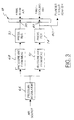
- FIGS. 1-3 illustrate an apparatus 10 for testing dual-stage blowheads, sometimes also referred to as isolated finish cooled blowheads, in accordance with a presently preferred embodiment of the invention.
- An adapter block 12 is mounted on a stand 14 carried by a base plate 16.
- a blowhead mounting cup 18 is removably mounted on adapter block 16.
- Cup 18 includes a holder 20 that is slidably mounted within a bearing 22 carried by block 12.
- Holder 20 has a center passage 24 that opens to a lateral passage 26, and thence through a passage 28 in block 12 to an inlet port 30.
- An annular channel 32 is formed on the flat lower face of holder 20, and is connected by a plurality of axial passages 34 to a radial channel 36 that opens to a second lateral passage 38 in block 12. Passage 38 terminates at an inlet port 40.
- a wear plate 42 is carried within a downwardly opening pocket 44 at the lower end of holder 18, and is urged downwardly by a coil spring 46 captured in compression within
- FIGS. 1 and 2 illustrate a dual-stage blowhead 48 having a central passage 50 for final blow air, and at least two peripheral angulated passages 52 for finish cooling air.
- Central passage 50 is coaxial with blowhead 48, while passages 52 are offset from the central axis of the blowhead and preferably diametrically disposed with respect to each other.
- Passages 52 open to an annular inlet 54 at the upper axial face of blowhead 48 concentrically surrounding final blow air passage 50, and communicates through openings 56 in wear plate 44 with channel 32 in holder 20.
- final blow air is fed from inlet port 30 through passages 28.
- a device 60 for simulating a container has an axial neck or "finish" inserted into the open lower end of blowhead 40 against the lower surface 64 of blowhead 48 radially between final hlow air passage 50 and finish cooling iir passages 52.
- device 60 simulates a container during the final-blow operation in terns of creating back pressure on air fed through passages 50, 52.
- FIGS. 1 and 2 illustrate a blowhead 48 and an associated blowhead mounting cup 18 in which the blowhead is mounted to the blowhead mounting cup by means of a conventional, releasable bayonet-type mounting arrangement. It will be appreciated that FIGS. 1-2 illustrate a single configuration of cup 18 and a single configuration of blowhead 48. Other configurations are conventionally employed. Indeed, facility for replaceable mounting of cup 18 in block 12 readily accommodates dual-stage blowheads of other configurations.
- apparatus 10 further comprises a pressure regulator 66 for connection to a common source of test air.
- Air is fed from pressure regulator 66 through apparatus 68 for measuring air pressure and mass air flow, and thence through a pressure regulator 70 to final blow air inlet 30 of adapter block 18.
- air from pressure regulator 66 is fed through apparatus 72 for measuring air pressure and mass air flow, and thence through a pressure regulator 74 to finish cooling air inlet 40 of adapter block 18.
- Both apparatus 68, 72 are carried by base plate 16, and regulators 70, 74 are mounted on apparatus 68, 72 respectively.
- a blowhead 48 is mounted in cup 18, a container-simulating device 60 is inserted into the blowhead, and apparatus 10 is connected to a source ol test air.
- Regulators 70, 74 are adjusted by an operator for controlling pressure of air fed to the final blow and finish cooling air inlets of the adapter block. Mass air flow and air pressure are then observed by an operator, and are compared to desired levels. These levels maybe determined empirically as absolute minimum desired air flow to a blowhead, or may he determined by comparing blowheads to each other for a single individual machine section. In this way, quantity of air flow maybe determined not only as an absolute measure, but also relative to other blowheads in a single machine section for optimum balance of operation. If a test blowhead does not exhibit desired air flow. this may indicate a need to rework or redrill the air flow passages in the blowhead. Alternatively, the blowhead may be simply replaced.
- a conduit branch 80 extends from pressure regulator 74 in the finish cooling test air path.
- Conduit 80 terminates in a plunger head adapter 82, which is internally threaded receive the external threads on the base of a plunger cooler.
- a plug 84 is threaded into head 82 effectively to block air flow through conduit 80.
- plug 84 is removed from head 82, a plunger cooler 86 is threaded into adapter 82, and air flow to adapter block inlet ports 30.40 is blocked (by means not shown).
- Air is thus fed under pressure through pressure and flow measurement apparatus 72 and pressure regulator 74 to plunger cooler 86 (FIG. 4), and flows out of the plunger cooler to the atmosphere through the multiplicity of air apertures 88 in the plunger cooler.
- the amount of air flow can be compared to an absolute level, determined either mathematically or empirically, or to other plunger coolers 86 from the same machine section, or to both. Low air flow may indicate a need to redrill or otherwise rework passages 88 in plunger cooler 86, or a need to provide a new plunger cooler.
Landscapes
- Engineering & Computer Science (AREA)
- Chemical & Material Sciences (AREA)
- Manufacturing & Machinery (AREA)
- Materials Engineering (AREA)
- Organic Chemistry (AREA)
- Blow-Moulding Or Thermoforming Of Plastics Or The Like (AREA)
- Aerodynamic Tests, Hydrodynamic Tests, Wind Tunnels, And Water Tanks (AREA)
- Examining Or Testing Airtightness (AREA)
Applications Claiming Priority (2)
| Application Number | Priority Date | Filing Date | Title |
|---|---|---|---|
| US09/466,515 US6460377B1 (en) | 1999-12-17 | 1999-12-17 | Method and apparatus for testing dual-stage blowheads |
| US466515 | 1999-12-17 |
Publications (1)
| Publication Number | Publication Date |
|---|---|
| EP1108687A1 true EP1108687A1 (en) | 2001-06-20 |
Family
ID=23852062
Family Applications (1)
| Application Number | Title | Priority Date | Filing Date |
|---|---|---|---|
| EP00127592A Withdrawn EP1108687A1 (en) | 1999-12-17 | 2000-12-15 | Method and apparatus for testing dual-stage blowheads |
Country Status (16)
| Country | Link |
|---|---|
| US (1) | US6460377B1 (enExample) |
| EP (1) | EP1108687A1 (enExample) |
| JP (1) | JP2001226124A (enExample) |
| CN (1) | CN1303824A (enExample) |
| AR (1) | AR026987A1 (enExample) |
| AU (1) | AU7231100A (enExample) |
| BR (1) | BR0005914A (enExample) |
| CA (1) | CA2328366A1 (enExample) |
| CO (1) | CO5290293A1 (enExample) |
| CZ (1) | CZ20004739A3 (enExample) |
| EE (1) | EE200000591A (enExample) |
| HU (1) | HUP0004965A3 (enExample) |
| MX (1) | MXPA00012601A (enExample) |
| PE (1) | PE20010916A1 (enExample) |
| PL (1) | PL344568A1 (enExample) |
| ZA (1) | ZA200007551B (enExample) |
Cited By (1)
| Publication number | Priority date | Publication date | Assignee | Title |
|---|---|---|---|---|
| WO2017068480A1 (en) * | 2015-10-19 | 2017-04-27 | Verreries Brosse S.A.S. | Method for producing glass bottles by automatic forming and apparatus to carry out the method |
Families Citing this family (3)
| Publication number | Priority date | Publication date | Assignee | Title |
|---|---|---|---|---|
| US6923022B1 (en) * | 2002-03-20 | 2005-08-02 | Owens-Brockway Glass Container Inc. | Dual-stage blowhead assembly |
| US7878027B2 (en) * | 2007-11-26 | 2011-02-01 | Owens-Brockway Glass Container Inc. | Glassware forming machine blowhead arm assembly |
| CN119394544A (zh) * | 2024-10-29 | 2025-02-07 | 中山市博测达电子科技有限公司 | 一种风筒密封及性能测试生产线 |
Citations (1)
| Publication number | Priority date | Publication date | Assignee | Title |
|---|---|---|---|---|
| EP0110695A1 (en) * | 1982-11-30 | 1984-06-13 | Emhart Industries, Inc. | Blowhead arrangement for a glassware container manufacturing machine |
Family Cites Families (16)
| Publication number | Priority date | Publication date | Assignee | Title |
|---|---|---|---|---|
| US2123145A (en) | 1936-10-30 | 1938-07-05 | Hartford Empire Co | Device for blowing and cooling glassware |
| US2198750A (en) | 1937-06-23 | 1940-04-30 | Crown Cork & Seal Co | Glassware forming method and apparatus |
| US2442315A (en) | 1944-11-24 | 1948-05-25 | S & Z Mfg Company Inc | Blow head for glass container making machines |
| US2627702A (en) | 1950-03-25 | 1953-02-10 | Earl L Lowe | Improvement in blowhead |
| US3403016A (en) | 1965-04-15 | 1968-09-24 | Anchor Hocking Glass Corp | Glassware forming apparatus with blow head control |
| US3871856A (en) | 1973-10-11 | 1975-03-18 | Emhart | Self-aligning baffle and blowhead assembly |
| US3946595A (en) | 1974-12-06 | 1976-03-30 | California Injection Molding Company, Inc. | Method and apparatus for testing mold vent orifices |
| US4453964A (en) | 1982-07-12 | 1984-06-12 | Maul Technology Corporation | Air distributing mechanism for glass forming apparatus |
| US4509969A (en) | 1983-03-04 | 1985-04-09 | Emhart Industries, Inc. | Blowhead apparatus |
| US4654066A (en) | 1983-10-18 | 1987-03-31 | Vitro Tec Fideicomiso | Electronic system to control cooling of molds in glassware forming machines |
| US4615722A (en) | 1985-09-20 | 1986-10-07 | Owens-Illinois, Inc. | Valve block test apparatus |
| GB8527643D0 (en) | 1985-11-08 | 1985-12-11 | Emhart Ind | Blowhead for manufacture of glass containers |
| US4838921A (en) | 1988-06-15 | 1989-06-13 | Emhart Industries, Inc. | Plunger assembly for a glassware forming machine |
| DE3907180A1 (de) * | 1989-03-06 | 1990-09-13 | Windmoeller & Hoelscher | Verfahren zum ueberpruefen der funktionsfaehigkeit von mit kuehlabschnitten versehenen extrusionsduesen von kunststoffextrudern zur herstellung von flach- oder schlauchfolien |
| US5139559A (en) | 1990-05-09 | 1992-08-18 | The Forming Edge, Inc. | Performance monitoring system for a glass container forming machine |
| US5537856A (en) | 1995-04-05 | 1996-07-23 | Purity Packaging, A Division Of Great Pacific Enterprises | Flow restriction detector for a nozzle assembly |
-
1999
- 1999-12-17 US US09/466,515 patent/US6460377B1/en not_active Expired - Fee Related
-
2000
- 2000-12-12 CA CA002328366A patent/CA2328366A1/en not_active Abandoned
- 2000-12-15 MX MXPA00012601A patent/MXPA00012601A/es unknown
- 2000-12-15 CZ CZ20004739A patent/CZ20004739A3/cs unknown
- 2000-12-15 AU AU72311/00A patent/AU7231100A/en not_active Abandoned
- 2000-12-15 AR ARP000106701A patent/AR026987A1/es unknown
- 2000-12-15 EE EEP200000591A patent/EE200000591A/xx unknown
- 2000-12-15 HU HU0004965A patent/HUP0004965A3/hu unknown
- 2000-12-15 EP EP00127592A patent/EP1108687A1/en not_active Withdrawn
- 2000-12-15 ZA ZA200007551A patent/ZA200007551B/xx unknown
- 2000-12-15 PL PL00344568A patent/PL344568A1/xx not_active Application Discontinuation
- 2000-12-15 PE PE2000001356A patent/PE20010916A1/es not_active Application Discontinuation
- 2000-12-16 CN CN00138057A patent/CN1303824A/zh active Pending
- 2000-12-18 BR BR0005914-5A patent/BR0005914A/pt not_active Application Discontinuation
- 2000-12-18 CO CO00095936A patent/CO5290293A1/es not_active Application Discontinuation
- 2000-12-18 JP JP2000404321A patent/JP2001226124A/ja active Pending
Patent Citations (1)
| Publication number | Priority date | Publication date | Assignee | Title |
|---|---|---|---|---|
| EP0110695A1 (en) * | 1982-11-30 | 1984-06-13 | Emhart Industries, Inc. | Blowhead arrangement for a glassware container manufacturing machine |
Cited By (2)
| Publication number | Priority date | Publication date | Assignee | Title |
|---|---|---|---|---|
| WO2017068480A1 (en) * | 2015-10-19 | 2017-04-27 | Verreries Brosse S.A.S. | Method for producing glass bottles by automatic forming and apparatus to carry out the method |
| US10934202B2 (en) | 2015-10-19 | 2021-03-02 | Verreries Brosse S.A.S. | Method for producing glass bottles by automatic forming and apparatus to carry out the method |
Also Published As
| Publication number | Publication date |
|---|---|
| HUP0004965A3 (en) | 2002-05-28 |
| CZ20004739A3 (cs) | 2001-08-15 |
| HU0004965D0 (enExample) | 2001-02-28 |
| AR026987A1 (es) | 2003-03-05 |
| CA2328366A1 (en) | 2001-06-17 |
| CN1303824A (zh) | 2001-07-18 |
| CO5290293A1 (es) | 2003-06-27 |
| BR0005914A (pt) | 2001-07-17 |
| EE200000591A (et) | 2001-08-15 |
| AU7231100A (en) | 2001-06-21 |
| PE20010916A1 (es) | 2001-09-12 |
| PL344568A1 (en) | 2001-06-18 |
| JP2001226124A (ja) | 2001-08-21 |
| US6460377B1 (en) | 2002-10-08 |
| MXPA00012601A (es) | 2003-04-25 |
| ZA200007551B (en) | 2001-07-12 |
| HUP0004965A2 (hu) | 2001-11-28 |
Similar Documents
| Publication | Publication Date | Title |
|---|---|---|
| US6460377B1 (en) | Method and apparatus for testing dual-stage blowheads | |
| US4678494A (en) | Blowhead arrangement for a glassware container manufacturing machine | |
| US5139559A (en) | Performance monitoring system for a glass container forming machine | |
| EP0217187B1 (en) | Fan air cooling of neck ring and parison mold | |
| US4104046A (en) | Temperature control for the forming units of a machine of the press and blow type | |
| ZA978365B (en) | Method and apparatus for delivering a cased glass stream. | |
| CA2344091A1 (en) | Final blow/finish cooling valve function monitor | |
| AU1951000A (en) | Pneumatic machine control unit for and I.S. machine | |
| US7748238B2 (en) | Neck ring cooling | |
| US1693069A (en) | Glass-forming machine | |
| JP2002121032A (ja) | ガラス塊の製造方法、ガラス成形品の製造方法、並びにガラス塊の製造装置 | |
| US4525191A (en) | Method of cooling a glass ware mould | |
| US7905113B2 (en) | Cooling tube mechanism for an I. S. Machine | |
| CN214053144U (zh) | 隐藏式常温氮气冷却装置及挤压装置 | |
| JPH0959031A (ja) | ガラスびん成形装置及びそのプランジャ装置 | |
| JP3987336B2 (ja) | ガラス製品用金型の冷却装置 | |
| CN1958487B (zh) | 玻璃制预成形件组、玻璃制预成形件的制造方法、光学元件的生产方法 | |
| CA2629693C (en) | Apparatus for finish cooling for a container glass machine | |
| EP1935855B1 (en) | Cooling tube mechanism for an I.S. machine | |
| US20070251274A1 (en) | Blank mold for an I.S. glass forming machine | |
| US7856852B2 (en) | Cooling tube mechanism for an I. S. Machine | |
| EP0121346A1 (en) | Blow mould cooling | |
| US910120A (en) | Glass-making machine. | |
| JPH07276487A (ja) | 中空成形機におけるブローピンの打込心出方法及びその装置 |
Legal Events
| Date | Code | Title | Description |
|---|---|---|---|
| PUAI | Public reference made under article 153(3) epc to a published international application that has entered the european phase |
Free format text: ORIGINAL CODE: 0009012 |
|
| AK | Designated contracting states |
Kind code of ref document: A1 Designated state(s): AT BE CH CY DE DK ES FI FR GB GR IE IT LI LU MC NL PT SE TR |
|
| AX | Request for extension of the european patent |
Free format text: AL;LT;LV;MK;RO;SI |
|
| AKX | Designation fees paid | ||
| REG | Reference to a national code |
Ref country code: DE Ref legal event code: 8566 |
|
| STAA | Information on the status of an ep patent application or granted ep patent |
Free format text: STATUS: THE APPLICATION IS DEEMED TO BE WITHDRAWN |
|
| 18D | Application deemed to be withdrawn |
Effective date: 20011221 |