EP1108570A2 - Luftgeferdertes Nutzfahrzeug mit einer angetriebenen Hinterachse und einer dieser beigeordneten Vor- oder Nachlaufachse - Google Patents
Luftgeferdertes Nutzfahrzeug mit einer angetriebenen Hinterachse und einer dieser beigeordneten Vor- oder Nachlaufachse Download PDFInfo
- Publication number
- EP1108570A2 EP1108570A2 EP00125539A EP00125539A EP1108570A2 EP 1108570 A2 EP1108570 A2 EP 1108570A2 EP 00125539 A EP00125539 A EP 00125539A EP 00125539 A EP00125539 A EP 00125539A EP 1108570 A2 EP1108570 A2 EP 1108570A2
- Authority
- EP
- European Patent Office
- Prior art keywords
- axle
- air
- rear axle
- pressure
- tons
- Prior art date
- Legal status (The legal status is an assumption and is not a legal conclusion. Google has not performed a legal analysis and makes no representation as to the accuracy of the status listed.)
- Granted
Links
Images
Classifications
-
- B—PERFORMING OPERATIONS; TRANSPORTING
- B60—VEHICLES IN GENERAL
- B60G—VEHICLE SUSPENSION ARRANGEMENTS
- B60G17/00—Resilient suspensions having means for adjusting the spring or vibration-damper characteristics, for regulating the distance between a supporting surface and a sprung part of vehicle or for locking suspension during use to meet varying vehicular or surface conditions, e.g. due to speed or load
- B60G17/02—Spring characteristics, e.g. mechanical springs and mechanical adjusting means
- B60G17/04—Spring characteristics, e.g. mechanical springs and mechanical adjusting means fluid spring characteristics
- B60G17/052—Pneumatic spring characteristics
Definitions
- the invention relates to a commercial vehicle, in particular a truck, with an air-sprung, driven rear axle, one of these associated leading or trailing axle as well one air suspension circuit with at least one air bag for each axle and axle side.
- the invention is based on the following prior art.
- Air suspension systems of the generic type where the desired between the driven rear axle and the leading or trailing axle Axle load ratio is produced by different air bag sizes.
- This axle load ratio is predetermined by the structural size of the air bellows therefore not changeable. This fact causes the air suspension of the commercial vehicle can only be designed according to legal or technical criteria could.
- the practical example outlined below illustrates the problem:
- the legally permissible axle load of the driven rear axle is z. B. 11.5 tons.
- the technically permissible axle load of this driven rear axle is 13 tons.
- the legally permissible single axle load is in usually identical to the technically permissible single axle load of z. B. 7.5 tons.
- Air suspension has been designed according to the technically permissible axle loads
- This Loss of just under 1 ton in the rear axle area very often causes chassis of Trucks, which are basically z. B. would be approved with a total weight of 26 tons, can only be approved with 25 tons.
- the invention thus allows automatic switching between legal and technical axle load ratio according to certain criteria.
- the relevant circuit is simple and inexpensive to implement and brings considerable benefits in practice.
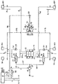
- the dashed-dotted line 1 is the driven rear axle and with the dash-dotted line 2 a leading or trailing axle associated with the rear axle 1 of a commercial vehicle, indicated in the example of a 3-axle truck.
- Each axis 1, 2 and a separate air spring circuit is provided on the axle side.
- the left-hand air spring circuit the rear axle 1 with 3 the right-hand air suspension circuit of the rear axle 1 with 4
- the Left-hand air spring circuit of the leading or trailing axle 2 with 5 and the right-hand air spring circuit the leading or trailing axle 2 with 6.
- each air spring circuit 5 or 6 of the leading or trailing axle 2 is only an air bellows 5/1 or 6/1 connected.
- At 7 is a compressed air source
- at 8 is an electronic Control unit for the electronically controlled compressed air supply in the vehicle
- 9 denotes a solenoid valve block.
- the solenoid valves of the solenoid valve block 9 are can be switched by control commands from the control unit 8 via signal lines 10, 11, as a result of which the Compressed air supply and control in the air spring circuits connected on the output side 3, 4, 5, 6 is feasible.
- With 12 is a double shut-off valve, both of which Inputs 13 and 14 each via a connecting line 15 and 16 with a branch 3/3 of the left air spring circuit 3 or 4/3 of the right air spring circuit 4 are connected and thus always get the current air pressure in the two air spring circuits 3, 4.
- the higher of the two appears at the outlet 17 of the double shut-off valve 12 fed in pressure values, which in the example shown by three pressure sensors 18, 19, 20 detected and used as indicated below.
- the pressure sensor 18 is provided because the leading or trailing axle 2 can be lifted in the example shown, that is to say completely can be brought into a raised position out of contact with the road.
- the pressure sensor 18 is used to detect an overload condition on the rear axle 1 and is If this state occurs, a corresponding signal is sent to the control unit via signal line 21 8, which then lowers the previously lifted leading or trailing axle 2 initiated.
- the pressure sensor 19, on the other hand, is provided because in the example shown, too partial relief of the air bellows 5/1, 6/1 of those in the lowered, carrying position Leading or trailing axle 2 is possible, with the aim of supporting the leading or trailing Reduce trailing axle 2 and the axle load on the rear axle 1 to improve traction to increase.
- the pressure value detected by the pressure sensor 19 is transmitted via the signal line 22 supplied to the control unit 8 and by the latter when the vehicle starts up - either automatically or upon a signal initiated by the driver a signal for partial relief of the air bellows 5/1, 6/1 in the air spring circuits 5, 6 the leading or trailing axle 2 implemented.
- the pressure sensor 20 is part of the invention Equipment of the vehicle and subsequently together with this explained.
- a first feature of the invention is that the size of the two axles Air bellows 3/1, 3/2; 4/1, 4/2 of the rear axle 1 according to the technically permissible Axle load of, for example, 13 tons is fixed, which in this example is air suspension bellows 3/1, 3/2; 4/1, 4/2, each with a diameter of 190 mm.
- a second A feature of the invention is that the size of the air bellows 5/1, 6/1 of the front or.
- a device which has an automatic Switching between legal and technical axle load ratio enabled.
- said device comprises two each between a fully open position and a pressure reducing position switchable pressure ratio valves 23, 24 - each Air spring circuit 3, 4 of the rear axle 1 - and the pressure sensor 20.
- the two pressure ratio valves 23, 24 are each in a compressed air control branch 3/4 of the left air spring circuit 3 or 4/4 of the right air spring circuit 4 installed between the solenoid valve block 9 and the two bellows 3/1, 3/2 and 4/1, 4/2 on each axle side of the rear axle 1 runs.
- both pressure ratio valves 23, 24 are until a loading state is reached of the vehicle that corresponds to the legally permissible axle load of the rear axle 1 of 11.5 tons in the example, switched to their pressure reducing position (this is in the drawing effectively shown), which means a pressure reduction of 7.5 in the example bar to 6.5 bar in the rear axle bellows 3/1, 3/2 or 4/1, 4/2 in the required Ratio of 1.15 in relation to that in the air bellows 5/1, 6/1 of the leading or trailing axle 2 allow the prevailing air pressure of 7.5 bar in the example.
- the axle load of the rear axle 1 via the pressure of at least one of the two Air spring circuits 3, 4 detecting pressure sensor 20 initiates according to the invention when the specified legally permissible rear axle load a switchover of the two pressure ratio valves 23, 24 in their fully open position, so that subsequently the technical Axle load ratio between rear axle load and front or trailing axle load due to the same Pressures of 7.5 bar in all air bellows 3/1, 3/2, 4/1, 4/2, 5/1, 6/1 in the example Rear axle 1 and leading and trailing axle 2 sets.
- the two pressure ratio valves 23, 24 are preferably by means of a compressed air signal switchable. For this they are in the example shown with their switching inputs above each a compressed air control line 25, 26 at the output 27 of a common compressed air switching valve 28 connected. This is when the legally permissible rear axle load is reached can be activated and released by the signal initiated in this regard by the pressure sensor 20 then the supply of switching air from the compressed air source 7 via the control lines 25, 26 to the two pressure ratio valves 23, 24, thereby synchronizing them from their previous one Pressure reduction position can be switched to its full open position, in which then a continuous connection in each compressed air control branch 3/4 or 4/4 from the solenoid valve block 9 to the two air suspension bellows 3/1, 3/2 or 4/1, 4/2 on each side of the rear axle 1 is given.
- Each pressure ratio valve 23, 24 has an exhaust throttle 29 or 30, which in its Pressure reduction position ensures a minimization of compressed air consumption. Besides, is each pressure ratio valve 23, 24 bypassed by a bypass branch 31 or 32, in the one Check valve 33 or 34 is installed so that air in the respective compressed air control branch 3/4 or 4/4 only from the air suspension bellows 3/1, 3/2 or 4/1, 4/2 connected to it is let through to the solenoid valve block 9.
- an electronic OR gate 35 is also provided has three OR signal inputs and an output 36. The latter is via a control line 37 connected to the switching element of the compressed air switching valve 28.
- the first OR signal input of the OR gate 35 is connected to the pressure sensor 20 via a control line 38 connected.
- the second OR signal input of the OR gate 35 is with the control unit 8 connected via a control line 39, via which if the leading or trailing axis 2 is in the lift position, a signal representative of this state for OR gate 35 is passed.
- the third OR signal input of the OR gate 35 receives transmit a signal from the control unit 8 via a control line 40, which is then output is when the air bellows 5/1, 6/1 of the leading and trailing axles are partially relieved 2 is done by an axle load increase on the rear axle 1 for a traction improvement to effect the same in the event of a start. Because of these connection conditions at the OR gate 35 results that when a signal is present at one of its three OR signal inputs the compressed air switching valve 28 receives a switching signal, that is activated and so that the pressure ratio valves 23, 24 are switched to their full open position. The latter causes the compressed air to be applied to the air bellows, as described above 3/1, 3/2, 4/1, 4/2 in the sense that the technical axle load ratio or sets a permissible overload on the rear axle 1.
Landscapes
- Engineering & Computer Science (AREA)
- Mechanical Engineering (AREA)
- Vehicle Body Suspensions (AREA)
Abstract
Description
- zwei jeweils zwischen einer Volldurchlaßstellung und einer Druckreduzierstellung umschaltbare Druckverhältnisventile - je Luftfederkreis der Hinterachse eines -, die beide bis zum Erreichen eines Beladungszustandes, der der gesetzlich zulässigen Achslast der Hinterachse von beispielsweise 11,5 Tonnen entspricht, in Druckreduzierstellung geschaltet sind und somit eine Reduzierung des Luftdruckes von z. B. 7,5 bar auf 6,5 bar in den Hinterachs-Luftfederbälgen im erforderlichen Verhältnis von z. B. 1,15 in Bezug auf den Luftdruck von beispielsweise 7,5 bar in den Luftfederbälgen der Vor- bzw. Nachlaufachse zulassen, und
- einen Drucksensor, der die Achslast der Hinterachse über den Druck wenigstens eines von deren beiden Luftfederkreisen erfaßt und bei Erreichen der gesetzlich zulässigen Hinterachslast die Umschaltung der beiden Druckverhältnisventile in Volldurchlaßstellung initiiert, so daß sich anschließend das technische Achslastverhältnis aufgrund gleicher Drücke von beispielsweise 7,5 bar in allen Luftfederbälgen der Hinterachse und Vor- bzw. Nachlaufachse einstellt.
Claims (6)
- Nutzfahrzeug, insbesondere Lastkraftwagen, mit einer luftgefederten, angetriebenen Hinterachse, einer dieser beigeordneten luftgefederten Vor- oder Nachlaufachse sowie je Achse und Achsseite einem Luftfederkreis mit je wenigstens einem Luftfederbalg, dadurch gekennzeichnet, daß die Größe der je Achsseite beiden Luftfederbälge (3/1, 3/2; 4/1, 4/2) der Hinterachse (1) und die Größe der Luftfederbälge (5/1, 6/1) der Vor- bzw. Nachlaufachse (2) entsprechend der jeweils technisch zulässigen Achsiast von beispielsweise 13 Tonnen bzw. 7,5 Tonnen festgelegt ist, sich somit ein technisches Achslastverhältnis von 13 Tonnen / 7,5 Tonnen = 1,73 ergibt, daß femer eine Vorrichtung zum automatischen Umschalten zwischen gesetzlichem und technischem Achslastverhältnis vorgesehen ist, wobei die gesetzlich zulässige Achslast der Hinterachse (1) beispielsweise 11,5 Tonnen und die gesetzlich zulässige Achslast der Nachlaufachse 11,5 Tonnen / 1,73 = 6,65 Tonnen beträgt und die besagte Vorrichtung folgende Teile aufweist, nämlichzwei jeweils zwischen einer Volldurchlaßstellung und einer Druckreduzierstellung umschaltbare Druckverhältnisventile (23, 24) - je Luftfederkreis (3, 4) der Hinterachse (1) eines -, die beide bis zum Erreichen eines Beladungszustandes, der der gesetzlich zulässigen Achslast der Hinterachse (1) von beispielsweise 11,5 Tonnen entspricht, in Druckreduzierstellung geschaltet sind und somit eine Reduzierung des Luftdruckes von z. B. 7,5 bar auf 6,5 bar in den Hinterachs-Luftfederbälgen (3/1, 3/2 bzw. 4/1, 4/2) im erforderlichen Verhältnis von z. B. 1,15 in Bezug auf den Luftdruck von beispielsweise 7,5 bar in den Luftfederbälgen (5/1, 6/1) der Vor- bzw. Nachlaufachse (2) zulassen, undeinen Drucksensor (20), der die Achslast der Hinterachse (1) über den Druck wenigstens eines von deren beiden Luftfederkreisen (3, 4) erfaßt und bei Erreichen der gesetzlich zulässigen Hinterachslast die Umschaltung der beiden Druckverhältnisventile (23, 24) in Volldurchlaßstellung initiiert, so daß sich anschließend das technische Achslastverhältnis aufgrund gleicher Drücke von beispielsweise 7,5 bar in allen Luftfederbälgen (3/1, 3/2, 4/1, 4/2, 5/1, 6/1) der Hinterachse (1) und Vor- bzw. Nachlaufachse (2) einstellt.
- Nutzfahrzeug nach Anspruch 1, dadurch gekennzeichnet, daß jedes der beiden Druckverhältnisventile (23, 24)in einen Druckluftregelzweig (3/4; 4/4) des linken und rechten Luftfederkreises (3, 4) eingebaut ist, der zwischen einem Magnetventilblock (9) und den beiden Luftfederbälgen (3/1, 3/2 bzw. 4/1, 4/2) je Achsseite der Hinterachse (1) verläuft, undmittels eines Druckluftsignales umschaltbar ist,
daß beide Druckverhältnisventile (23, 24) mit ihren Schalteingängen über jeweils eine Druckluftsteuerleitung (25, 26) am Ausgang (27) eines gemeinsamen Druckluftschaltventils (28) angeschlossen sind, das bei Anliegen eines vom Drucksensor (20) bei Erreichen der gesetzlich zulässigen Hinterachslast initiierten Signals aktivierbar ist und dann das Zuführen von Schaltluft zu den beiden Druckverhältnisventilen (23, 24) für deren synchrone Umschaltung in Volldurchlaßstellung zuläßt, in der dann eine luftdurchgängige Verbindung in jedem Druckluftregelzweig (3/4 bzw. 4/4) vom Magnetventilblock (9) zu den jeweils beiden Luftfederbälgen (3/1, 3/2 bzw. 4/1, 4/2) je Achsseite der Hinterachse (1) hin gegeben ist. - Nutzfahrzeug nach Anspruch 2, dadurch gekennzeichnet, daß jedes Druckverhältnisventil (23, 24) eine für eine Minimierung des Druckluftverbrauchs in seiner Druckreduzierstellung sorgende Abluftdrossel (29 bzw. 30) aufweist.
- Nutzfahrzeug nach Anspruch 2, dadurch gekennzeichnet, daß jedes Druckverhältnisventil (23, 24) von einem Bypasszweig (31 bzw. 32) umgangen ist, in den ein Rückschlagventil (33 bzw. 34) eingebaut ist, das Luft im jeweiligen Druckluftregelzweig (3/4; 4/4) nur von den an diesem angeschlossenen Luftfederbälgen (3/1, 3/2 bzw. 4/1, 4/2) der Hinterachse (1) her zum Magnetventilblock (9) hin durchläßt.
- Nutzfahrzeug nach Anspruch 1, dadurch gekennzeichnet, daß der Drucksensor (20) am gemeinsamen Ausgang (17) eines Doppelabsperrventiles (12) angeschlossen ist, dessen beide Eingänge (13, 14) jeweils über eine Anschlußleitung (15, 16) mit dem linken bzw. rechten Luftfederkreis (3 bzw. 4) der Hinterachse (1) in Verbindung stehen.
- Nutzfahrzeug nach Anspruch 2, dadurch gekennzeichnet, daß in dem Fall, wenn die Voroder Nachlaufachse (2) liftbar ist und/oder die Luftfederbälge (5/1, 6/1) der sich in abgesenkter Mittragstellung befindlichen Vor- bzw. Nachlaufachse (2) für eine Verbesserung der Traktion der angetriebenen Hinterachse (1) beim Anfahren teilentlastbar sind durch entsprechende Steuerbefehle der elektronischen Steuereinheit (8), ein elektronisches ODER-Gatter (35) vorgesehen ist, das drei ODER-Signaleingänge und einen Ausgang (36) aufweist, wobeider Ausgang (36) über eine Steuerleitung (37) mit dem Schaltorgan des Druckluftschaltventils (28),der erste ODER-Signaleingang über eine Steuerleitung (38) mit dem Drucksensor (20),der zweite ODER-Signaleingang über eine die Liftstellung der Vor- bzw. Nachlaufachse (2) signalisierende Steuerleitung (39) mit der Steuereinheit (8), undder dritte ODER-Signaleingang über eine die Teil-Entlastung der Luftfederbälge (5/1, 6/1) der Vor- bzw. Nachlaufachse (2) im Anfahrfall signalisierende Steuerleitung (40) ebenfalls mit der Steuereinheit (8)
verbunden ist, so daß bei Anliegen eines Signals an einem der drei ODER-Signaleingänge das Druckluftschaltventil (28) ein Signal erhält, durch dieses aktivierbar ist und dann die Druckverhältnisventile (23, 24) in ihre Volldurchlaßstellung umschaltbar sind.
Applications Claiming Priority (2)
| Application Number | Priority Date | Filing Date | Title |
|---|---|---|---|
| AT209999 | 1999-12-14 | ||
| AT0209999A AT408429B (de) | 1999-12-14 | 1999-12-14 | Nutzfahrzeug, insbesondere lastkraftwagen, mit einer luftgefederten, angetriebenen hinterachse und einer dieser beigeordneten luftgefederten vor- und nachlaufachse |
Publications (3)
| Publication Number | Publication Date |
|---|---|
| EP1108570A2 true EP1108570A2 (de) | 2001-06-20 |
| EP1108570A3 EP1108570A3 (de) | 2004-02-04 |
| EP1108570B1 EP1108570B1 (de) | 2007-09-19 |
Family
ID=3527729
Family Applications (1)
| Application Number | Title | Priority Date | Filing Date |
|---|---|---|---|
| EP00125539A Expired - Lifetime EP1108570B1 (de) | 1999-12-14 | 2000-11-22 | Luftgefedertes Nutzfahrzeug mit einer angetriebenen Hinterachse und einer dieser beigeordneten Vor- oder Nachlaufachse |
Country Status (3)
| Country | Link |
|---|---|
| EP (1) | EP1108570B1 (de) |
| AT (2) | AT408429B (de) |
| DE (1) | DE50014665D1 (de) |
Cited By (6)
| Publication number | Priority date | Publication date | Assignee | Title |
|---|---|---|---|---|
| DE102006011183A1 (de) * | 2006-03-10 | 2007-09-13 | Wabco Gmbh | Verfahren zur Traktionsregelung eines pneumatisch gefederten Fahrzeuges |
| DE102010053264A1 (de) * | 2010-12-02 | 2012-06-06 | Wabco Gmbh | Verfahren zur Steuerung des Druckausgleichs bei einem Fahrwerk mit einer Antriebsachse und einer Schleppachse |
| EP2662228A2 (de) | 2012-05-11 | 2013-11-13 | MAN Truck & Bus AG | Luftfederung eines Nutzfahrzeugs mit Achslastumschaltung zwischen Hinterachse und Vor- oder Nachlaufachse |
| CN111873735A (zh) * | 2020-07-24 | 2020-11-03 | 中国重汽集团济南动力有限公司 | 一种商用车轻量化空气悬架提升装置、方法及车辆 |
| CN112297743A (zh) * | 2019-08-01 | 2021-02-02 | 十堰科纳汽车电子股份有限公司 | 一种可避免空气悬架驱动桥失载的结构 |
| CN115519956A (zh) * | 2022-10-13 | 2022-12-27 | 东风商用车有限公司 | 一种6×4r牵引车驱动桥动力系统 |
Family Cites Families (5)
| Publication number | Priority date | Publication date | Assignee | Title |
|---|---|---|---|---|
| DE3428867A1 (de) * | 1984-08-04 | 1986-02-13 | Wabco Westinghouse Fahrzeugbremsen GmbH, 3000 Hannover | Luftfedereinrichtung fuer fahrzeuge |
| US4700968A (en) * | 1986-04-07 | 1987-10-20 | Lear Siegler, Inc. | Liftable axle with load control |
| DE3724696A1 (de) * | 1987-07-25 | 1989-02-02 | Bosch Gmbh Robert | Verfahren zur regelung einer druckluftgestuetzten fahrzeugfederung |
| DE3925196A1 (de) * | 1989-07-29 | 1991-02-07 | Iveco Magirus | Anfahrhilfe fuer luftgefederte mehrachs-fahrzeuge mit liftbarer zusatzachse |
| SE9803782D0 (sv) * | 1998-11-05 | 1998-11-05 | Volvo Lastvagnar Ab | Anordning vid hjulupphängning i ett lastfordon |
-
1999
- 1999-12-14 AT AT0209999A patent/AT408429B/de not_active IP Right Cessation
-
2000
- 2000-11-22 EP EP00125539A patent/EP1108570B1/de not_active Expired - Lifetime
- 2000-11-22 AT AT00125539T patent/ATE373575T1/de not_active IP Right Cessation
- 2000-11-22 DE DE50014665T patent/DE50014665D1/de not_active Expired - Fee Related
Non-Patent Citations (1)
| Title |
|---|
| None |
Cited By (13)
| Publication number | Priority date | Publication date | Assignee | Title |
|---|---|---|---|---|
| DE102006011183A1 (de) * | 2006-03-10 | 2007-09-13 | Wabco Gmbh | Verfahren zur Traktionsregelung eines pneumatisch gefederten Fahrzeuges |
| ES2336056A1 (es) * | 2006-03-10 | 2010-04-07 | Wabco Gmbh | Procedimiento para la regulacion de la traccion de un vehiculo con suspension neumatica. |
| ES2336056B2 (es) * | 2006-03-10 | 2010-09-29 | Wabco Gmbh | Procedimiento para la regulacion de la traccion de un vehiculo con suspension neumatica. |
| DE102006011183B4 (de) * | 2006-03-10 | 2015-02-19 | Wabco Gmbh | Verfahren zur Traktionsregelung eines pneumatisch gefederten Fahrzeuges |
| DE102010053264A1 (de) * | 2010-12-02 | 2012-06-06 | Wabco Gmbh | Verfahren zur Steuerung des Druckausgleichs bei einem Fahrwerk mit einer Antriebsachse und einer Schleppachse |
| EP2662228A3 (de) * | 2012-05-11 | 2014-07-23 | MAN Truck & Bus AG | Luftfederung eines Nutzfahrzeugs mit Achslastumschaltung zwischen Hinterachse und Vor- oder Nachlaufachse |
| DE102012009383A1 (de) | 2012-05-11 | 2013-11-14 | Man Truck & Bus Ag | Luftfederung eines Nutzfahrzeugs mit Achslastumschaltung zwischen Hinterachse und Vor- oder Nachlaufachse |
| EP2662228A2 (de) | 2012-05-11 | 2013-11-13 | MAN Truck & Bus AG | Luftfederung eines Nutzfahrzeugs mit Achslastumschaltung zwischen Hinterachse und Vor- oder Nachlaufachse |
| RU2587739C2 (ru) * | 2012-05-11 | 2016-06-20 | Ман Трак Унд Бас Аг | Пневматическая подвеска автомобиля промышленного назначения, снабженная системой переключения нагрузки на оси между задней осью и поддерживающей осью, установленной впереди или позади приводной оси |
| CN112297743A (zh) * | 2019-08-01 | 2021-02-02 | 十堰科纳汽车电子股份有限公司 | 一种可避免空气悬架驱动桥失载的结构 |
| CN111873735A (zh) * | 2020-07-24 | 2020-11-03 | 中国重汽集团济南动力有限公司 | 一种商用车轻量化空气悬架提升装置、方法及车辆 |
| CN111873735B (zh) * | 2020-07-24 | 2023-09-05 | 中国重汽集团济南动力有限公司 | 一种商用车轻量化空气悬架提升装置、方法及车辆 |
| CN115519956A (zh) * | 2022-10-13 | 2022-12-27 | 东风商用车有限公司 | 一种6×4r牵引车驱动桥动力系统 |
Also Published As
| Publication number | Publication date |
|---|---|
| AT408429B (de) | 2001-11-26 |
| DE50014665D1 (de) | 2007-10-31 |
| ATA209999A (de) | 2001-04-15 |
| ATE373575T1 (de) | 2007-10-15 |
| EP1108570B1 (de) | 2007-09-19 |
| EP1108570A3 (de) | 2004-02-04 |
Similar Documents
| Publication | Publication Date | Title |
|---|---|---|
| EP1212205B1 (de) | Steueranlage zum heben und senken des fahrzeugaufbaus von luftgefederten fahrzeugen mit niveauregelung | |
| EP2058188B9 (de) | Steueranlage für Kraftfahrzeug-Anhänger mit Betriebsbremse, Feststellbremse und Luftfederung | |
| DE102009011606A1 (de) | Vorrichtung und Verfahren zum Durchführen einer Radstandregelung für Nutzfahrzeuge | |
| EP3744590B1 (de) | Bremssystem für einen landwirtschaftlich einsetzbaren anhänger sowie landwirtschaftlicher zugverbund, umfassend eine zugmaschine und wenigstens einen damit gekoppelten anhänger | |
| DE102008051546B4 (de) | Luftfederanlage für einen Kraftwagen mit wenigstens einer Ventilanordnung für eine Liftachse des Kraftwagens | |
| DE4317847A1 (de) | Einrichtung zum Steuern der Schleppachse eines Fahrzeugs | |
| EP0372218A2 (de) | Verfahren zur Regelung einer druckluftgestützten Fahrzeugfederung | |
| EP0365953B1 (de) | Reifendruckregelanlage für geländegängige Kraftfahrzeuge | |
| DE102007012242A1 (de) | Verfahren zur Verkleinerung des Wendekreises von Nutzfahrzeugen | |
| EP1060966A2 (de) | Anhängerbremsventil für blockiergeschützte Druckluftbremsanlagen von Anhängern | |
| EP1108570B1 (de) | Luftgefedertes Nutzfahrzeug mit einer angetriebenen Hinterachse und einer dieser beigeordneten Vor- oder Nachlaufachse | |
| DE3818617C2 (de) | ||
| EP3705322B1 (de) | Verfahren zur niveauregulierung eines luftgefederten fahrzeugs | |
| EP4197829A1 (de) | Ventilanordnung und verfahren zur steuerung einer anhebbaren schleppachse eines anhängefahrzeuges | |
| EP0238891B1 (de) | Entlastung der Nachlaufachse bei einem Doppelachsenfahrzeug | |
| DE19546056A1 (de) | Hydraulische Bremsanlage mit Hochdruckquelle und pedalbetätigtem Dosierventil | |
| EP3744587B1 (de) | Bremsanlage für eine landwirtschaftliche arbeitsmaschine sowie landwirtschaftlicher zugverbund, umfassend eine zugmaschine und wenigstens eine damit gekoppelte arbeitsmaschine | |
| EP2662228B1 (de) | Luftfederung eines Nutzfahrzeugs mit Achslastumschaltung zwischen Hinterachse und Vor- oder Nachlaufachse | |
| EP0352426B1 (de) | Vorrichtung zum Zu- und Abschalten der Mittragfunktion einer Mitlauf- oder Liftachse | |
| EP1647473B1 (de) | Anlage für Kraftfahrzeuge mit Luftfederung und Liftachse | |
| EP3882056B1 (de) | Verfahren zur steuerung einer luftfederungsanlage eines fahrzeugs | |
| DE102015118049A1 (de) | Fahrzeug mit verbesserter Anhängervorrichtung | |
| EP2769858B1 (de) | Einrichtung zur steuerung der deichsellast bei mehrachsigen anhängern | |
| DE102023114352A1 (de) | Verfahren zum Befüllen von Druckluftverbraucherkreisen eines Fahrzeugs | |
| DE102015224996A1 (de) | Fahrzeug mit Anhänger mit Aufhängungssystem |
Legal Events
| Date | Code | Title | Description |
|---|---|---|---|
| PUAI | Public reference made under article 153(3) epc to a published international application that has entered the european phase |
Free format text: ORIGINAL CODE: 0009012 |
|
| AK | Designated contracting states |
Kind code of ref document: A2 Designated state(s): AT BE CH CY DE DK ES FI FR GB GR IE IT LI LU MC NL PT SE TR |
|
| AX | Request for extension of the european patent |
Free format text: AL;LT;LV;MK;RO;SI |
|
| RAP1 | Party data changed (applicant data changed or rights of an application transferred) |
Owner name: MAN SONDERFAHRZEUGE AG |
|
| PUAL | Search report despatched |
Free format text: ORIGINAL CODE: 0009013 |
|
| AK | Designated contracting states |
Kind code of ref document: A3 Designated state(s): AT BE CH CY DE DK ES FI FR GB GR IE IT LI LU MC NL PT SE TR |
|
| AX | Request for extension of the european patent |
Extension state: AL LT LV MK RO SI |
|
| RIC1 | Information provided on ipc code assigned before grant |
Ipc: 7B 62D 61/12 B Ipc: 7B 60G 11/27 B Ipc: 7B 60G 17/015 B Ipc: 7B 60G 17/052 A |
|
| 17P | Request for examination filed |
Effective date: 20040110 |
|
| AKX | Designation fees paid |
Designated state(s): AT DE FR IT NL SE |
|
| RAP1 | Party data changed (applicant data changed or rights of an application transferred) |
Owner name: MAN NUTZFAHRZEUGE OESTERREICH AG |
|
| GRAP | Despatch of communication of intention to grant a patent |
Free format text: ORIGINAL CODE: EPIDOSNIGR1 |
|
| GRAS | Grant fee paid |
Free format text: ORIGINAL CODE: EPIDOSNIGR3 |
|
| GRAA | (expected) grant |
Free format text: ORIGINAL CODE: 0009210 |
|
| AK | Designated contracting states |
Kind code of ref document: B1 Designated state(s): AT DE FR IT NL SE |
|
| REF | Corresponds to: |
Ref document number: 50014665 Country of ref document: DE Date of ref document: 20071031 Kind code of ref document: P |
|
| REG | Reference to a national code |
Ref country code: SE Ref legal event code: TRGR |
|
| PGFP | Annual fee paid to national office [announced via postgrant information from national office to epo] |
Ref country code: NL Payment date: 20071119 Year of fee payment: 8 Ref country code: DE Payment date: 20071123 Year of fee payment: 8 |
|
| PGFP | Annual fee paid to national office [announced via postgrant information from national office to epo] |
Ref country code: AT Payment date: 20071116 Year of fee payment: 8 Ref country code: IT Payment date: 20071123 Year of fee payment: 8 |
|
| PGFP | Annual fee paid to national office [announced via postgrant information from national office to epo] |
Ref country code: SE Payment date: 20071114 Year of fee payment: 8 |
|
| PGFP | Annual fee paid to national office [announced via postgrant information from national office to epo] |
Ref country code: FR Payment date: 20071122 Year of fee payment: 8 |
|
| ET | Fr: translation filed | ||
| PLBE | No opposition filed within time limit |
Free format text: ORIGINAL CODE: 0009261 |
|
| STAA | Information on the status of an ep patent application or granted ep patent |
Free format text: STATUS: NO OPPOSITION FILED WITHIN TIME LIMIT |
|
| 26N | No opposition filed |
Effective date: 20080620 |
|
| EUG | Se: european patent has lapsed | ||
| PG25 | Lapsed in a contracting state [announced via postgrant information from national office to epo] |
Ref country code: NL Free format text: LAPSE BECAUSE OF NON-PAYMENT OF DUE FEES Effective date: 20090601 |
|
| NLV4 | Nl: lapsed or anulled due to non-payment of the annual fee |
Effective date: 20090601 |
|
| PG25 | Lapsed in a contracting state [announced via postgrant information from national office to epo] |
Ref country code: IT Free format text: LAPSE BECAUSE OF NON-PAYMENT OF DUE FEES Effective date: 20081122 Ref country code: AT Free format text: LAPSE BECAUSE OF NON-PAYMENT OF DUE FEES Effective date: 20081122 |
|
| REG | Reference to a national code |
Ref country code: FR Ref legal event code: ST Effective date: 20090731 |
|
| PG25 | Lapsed in a contracting state [announced via postgrant information from national office to epo] |
Ref country code: DE Free format text: LAPSE BECAUSE OF NON-PAYMENT OF DUE FEES Effective date: 20090603 |
|
| PG25 | Lapsed in a contracting state [announced via postgrant information from national office to epo] |
Ref country code: SE Free format text: LAPSE BECAUSE OF NON-PAYMENT OF DUE FEES Effective date: 20081123 |
|
| PG25 | Lapsed in a contracting state [announced via postgrant information from national office to epo] |
Ref country code: FR Free format text: LAPSE BECAUSE OF NON-PAYMENT OF DUE FEES Effective date: 20081130 |