EP1107879B1 - Motor Vehicle Tray - Google Patents
Motor Vehicle Tray Download PDFInfo
- Publication number
- EP1107879B1 EP1107879B1 EP98941172A EP98941172A EP1107879B1 EP 1107879 B1 EP1107879 B1 EP 1107879B1 EP 98941172 A EP98941172 A EP 98941172A EP 98941172 A EP98941172 A EP 98941172A EP 1107879 B1 EP1107879 B1 EP 1107879B1
- Authority
- EP
- European Patent Office
- Prior art keywords
- cord
- lateral edge
- wheel
- slot
- back face
- Prior art date
- Legal status (The legal status is an assumption and is not a legal conclusion. Google has not performed a legal analysis and makes no representation as to the accuracy of the status listed.)
- Expired - Lifetime
Links
Images


Classifications
-
- B—PERFORMING OPERATIONS; TRANSPORTING
- B60—VEHICLES IN GENERAL
- B60N—SEATS SPECIALLY ADAPTED FOR VEHICLES; VEHICLE PASSENGER ACCOMMODATION NOT OTHERWISE PROVIDED FOR
- B60N3/00—Arrangements or adaptations of other passenger fittings, not otherwise provided for
- B60N3/001—Arrangements or adaptations of other passenger fittings, not otherwise provided for of tables or trays
- B60N3/002—Arrangements or adaptations of other passenger fittings, not otherwise provided for of tables or trays of trays
- B60N3/005—Arrangements or adaptations of other passenger fittings, not otherwise provided for of tables or trays of trays mounted on the steering wheel
Definitions
- Supporting trays adapted for mounting on the steering wheel of a motor vehicle are known by various documents, among others US 4,915,035, US 3,643,606, US 3,952,988, BE 906,068, BE 794,697.
- the tray of US 4,915,035 is provided with two right angle frames slidably engaging the wheel.
- the said frames need to be sufficiently rigid so as to be able to resist to the forces and moments exerted when placing foods or drinks on the tray.
- the tray of BE 906,068 comprises two plates linked together by means of an articulation and by means of two cords so as to maintain a first plate substantially horizontal when the other plate rests on the wheel.
- Said other plate is mounted on the wheel by (a) two supporting blocks contacting the wheel and (b) an elastic band.
- the placement of this tray on a wheel is quite complicated and the elastic band has to be adapted for resisting the weight of the foods and drinks placed on the first plate.
- Document GB-A-1 550 899 describes a motor vehicle tray which comprises two panels, i.e. a mounting panel and a shelf hinaedly connected to the mounting panel.
- the back surface of the mounting panel is "provided with a pair of rearwardly extending hook pieces whose openings face one another and which enable the mounting panel to be mounted onto the steering wheel.
- the present invention has for subject matter a device with supporting tray which can easily be mounted on the steering wheel of a motor vehicle.
- the supporting tray when mounted on the wheel is stable. Furthermore, in case of inadequate placement of the tray whereby the tray does not extend in a horizontal plane, the tray can easily be moved with respect to the wheel so as to extend in a substantially horizontal plane.
- the invention as defined in claim 1 relates to a device with supporting tray adapted for mounting on a substantially circular wheel of a motor vehicle, said device comprising
- the larger edges of the rectangular opening have a length of at least 20 cm, for example between 20 and 30 cm, more specifically about 25 cm.
- the small edges of the opening have a length for example from 3 to 7 cm, more specifically about 5 cm.
- the opening of the second part is distant from the first pivotal line, whereby after mounting the second part on die wheel by sliding the opening along said wheel, the back face of the first part only contacts the wheel in the neighbourhood of the second pivotal line, the part of said back face of the first part adjacent to the first pivotal line being distant from the wheel.
- the opening of the second part has a larger edge adjacent to the first pivotal line, but located at a distance of at least 0.5 cm from said first pivotal line, whereby after mounting the second part on the wheel by sliding the opening along said wheel, the back face of the first part only contacts the wheel in the neighbourhood of the second pivotal line, the part of said back face of the first part adjacent to the first pivotal line being distant from said wheel of at least 0.5 cm.
- the means for linking the first part and the third part together for maintaining the third part substantially horizontal consists of links provided with means for adjusting the length of the links between the first and the third parts.
- the means for linking the first part and the third part together for maintaining the third part substantially horizontal consists of links provided with stops, the stops of each link co-operating with an opening of the third part so as to adjust the length of the link between the first and the third part.
- the means for linking the third part and the first part together consists of a first cord provided with stops and a second cord provided with stops, each cord being attached to the third part, the first cord being inserted in the first slot so that one stop of the cord abuts against the back face of the first part, while the second cord is inserted in the second slot so that one stop of the cord abuts against the back face of the first part.
- the means for linking the third part and the first part together consists of a first cord provided with stops and a second cord provided with stops, each cord being attached to the first part, the first cord being inserted in the first slot so that one stop of the cord abuts against the back face of the third part, while the second cord is inserted in the second slot so that one stop of the cord abuts against the back face of the third part.
- the means for linking the third part and the first part together consists of a first cord provided with stops and a second cord provided with stops, the first cord being inserted in the first slot of the first part and in the first slot of the third part so that one stop of the cord abuts against the back face of the first part, while another stop of the cord abuts against the back face of the third part, while the second cord is inserted in the second slot of the first part and in the second slot of the third part so that one stop of the cord abuts against the back face of the first part, while another stop of the cord abuts against the back face of the third part, while the second cord is inserted in the second slot of the first part and in the second slot of the third part so that one stop of the cord abuts against the back face of the first part, while another stop of the cord abuts
- the rigid panel can be made from various types of cardboard, plywood, metal, plastic material (such as rigid PVC) or any other material which is sufficiently rigid to support the articles which are intended to be held by the device.
- the pivotal lines are advantageously formed by a means extending between the two opposite lateral edges of the panel, said means being for example selected from the group consisting of grooves, partial cuttings, cuttings extending partly in the thickness of the panel, rows of holes, and combinations thereof.
- the first and second pivotal lines are formed respectively by a first groove extending between the two lateral edges of the panel and a second groove extending between the two lateral edges of the panel, the first groove being located on the front face of the panel, while the second groove is located on the back face of the panel.
- the rigid panel is made from a material such as plywood, metal or rigid PVC, it may be appropriate or even necessary that the first part of the panel be connected to the second part and to the third part respectively, by way of hinges (e.g. piano hinges) or by way of pliable strips.
- hinges e.g. piano hinges
- the slots of the first and/or third part are not parallel to the pivotal lines and extend between a first end located along one lateral edge of the panel and a second end, the distance separating said second end from the second pivotal line being lower than the distance separating the first end from the second pivotal line.
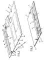
- the tray device shown in Fig 1 has a supporting tray adapted for mounting on a substantially circular steering wheel 8 of a motor vehicle. Said device comprises:
- the opening 7 of the second part 4 has a larger edge 7A adjacent to the first pivotal line 2, but located at a distance X of about 2.5 cm from said first pivotal line 2, whereby after mounting the second part 4 on the wheel 8 by sliding the opening 7 along said wheel 8, the back face 1B of the first part 5 only contacts the wheel 8 in the neighbourhood of the second pivotal line 3, the part of said back face 1B of the first part 5 adjacent to the first pivotal line 2 being distant from said wheel 8 of about 2.5 cm.
- the cords 9 are provided with stops 91 for adjusting the length L of the parts of the cords extending between the first and the third parts 5,6. Stops 91 of each cord 9 cooperate with slots 20,21,22,23 of the first and third parts 5,6 so as to adjust the length L of the link between the first and the third part.
- the first part 5 extends between a first lateral edge 5A and a second lateral edge 5B and has a first slot 20 extending from said first lateral edge 5A and a second slot 21 extending from the second lateral edge 5B, said slots 20,21 being adjacent to the first pivotal line 2 (for example at a distance of less than 5 cm of said pivotal line 2).
- the third part 6 extends between a first lateral edge 6A and a second lateral edge 6B and has a first slot 22 extending from said first lateral edge 6A and a second slot 23 extending from the second lateral edge 6B, said slots being distant from the second pivotal line of at least 10 cm.
- a first cord 9 is inserted in the first slot 20 of the first part 5 and in the first slot 22 of the third part 6 so that one stop 91 of the cord 9 abuts against the back face 1B of the first part 5, while another stop 91 of the cord abuts against the back face 1B of the third part 6.
- a second cord 9 is inserted in the second slot 21 of the first part 5 and in the second slot 23 of the third part 6 so that one stop 91 of the cord 9 abuts against the back face of the first part 5, while another stop 91 of the cord abuts against the back face of the third part 6.
- the first and second pivotal lines 2,3 are formed respectively by a first groove 2 extending between the two lateral edges of the panel 1 and a second groove 3 extending between the two lateral edges of the panel, a first groove 2 being located on the front face 1A of the panel, while the second groove 3 is located on the back face 1B of the panel.
- the slots 20,21,22,23 are not parallel to the pivotal lines 2,3 and extend between a first end Y located along one lateral edge of the panel and a second end Z, the distance E separating said second end Z from the second pivotal line 3 being lower than the distance F separating the first end Y from the second pivotal line 3. This is advantageous for preventing the removal of the cord out of the slot when the tray device is mounted on the wheel.
- the third part 6 can be provided with an opening 10, in which a glass 11 can partly be inserted.
- Said third part when positioned in a substantially horizontal plane, is suitable for supporting various elements or pieces, for example a lunch plate, a personal computer (such as a lap top or notebook), a book, writing material, etc.
- the slots 22,23 are located in the neighbourhood of the free end of the part 6, for example at a distance from the second pivotal line 3 corresponding to more than 50% of the distance separating the free end of the part 6 and the second pivotal line. Especially, the slots 22,23 are located at a distance from the pivotal line 3 of more than 66% of the distance between the free end of the part 6 and the second pivotal line 3.
- the distance between the two pivotal lines 2 and 3 is lower than the distance between the second pivotal line and the free end of the part 6.
- the distance between the two pivotal lines 2 and 3 is greater than the distance between the second pivotal line and the free end of the part 6.
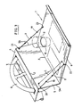
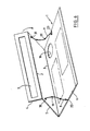
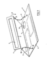
- Fig 5 shows the folding back (pivotment R) of the tray device of Fig 3, so as to reach the compact position shown in Fig 2.
- Figures 6 and 7 are views of embodiments similar to that shown in Fig 5, except that in Fig 6, the slots 20,21 have been replaced by holes 30,31, while in Fig 7, the slots 22,23 have been replaced by the holes 32,33.
- pivotal lines 2,3 instead of using grooves for forming the pivotal lines 2,3 as shown in Fig. 1, it is possible to use partial cuttings, a serial of partial cuttings or openings extending through the thickness of the panel, rows of holes, and combinations thereof for forming said pivotal lines 2,3.
- the slots 20,21,22,23 are straight in the Figures, however said slots can possibly be curved towards the second pivotal lines 3.
Landscapes
- Engineering & Computer Science (AREA)
- Transportation (AREA)
- Mechanical Engineering (AREA)
- Handcart (AREA)
- Passenger Equipment (AREA)
- Vehicle Step Arrangements And Article Storage (AREA)
- Motor Or Generator Cooling System (AREA)
Applications Claiming Priority (1)
| Application Number | Priority Date | Filing Date | Title |
|---|---|---|---|
| PCT/BE1998/000126 WO2000012352A1 (en) | 1998-08-26 | 1998-08-26 | Motor vehicle tray |
Publications (2)
| Publication Number | Publication Date |
|---|---|
| EP1107879A1 EP1107879A1 (en) | 2001-06-20 |
| EP1107879B1 true EP1107879B1 (en) | 2003-10-01 |
Family
ID=3891102
Family Applications (1)
| Application Number | Title | Priority Date | Filing Date |
|---|---|---|---|
| EP98941172A Expired - Lifetime EP1107879B1 (en) | 1998-08-26 | 1998-08-26 | Motor Vehicle Tray |
Country Status (10)
| Country | Link |
|---|---|
| EP (1) | EP1107879B1 (enExample) |
| JP (1) | JP2002523293A (enExample) |
| AT (1) | ATE251051T1 (enExample) |
| AU (1) | AU750097B2 (enExample) |
| BR (1) | BR9815995A (enExample) |
| CA (1) | CA2340127A1 (enExample) |
| DE (1) | DE69818715T2 (enExample) |
| ES (1) | ES2209193T3 (enExample) |
| MX (1) | MXPA01001998A (enExample) |
| WO (1) | WO2000012352A1 (enExample) |
Families Citing this family (4)
| Publication number | Priority date | Publication date | Assignee | Title |
|---|---|---|---|---|
| FR2810281A1 (fr) * | 2000-06-16 | 2001-12-21 | Gyba | Dispositif de type plateau notamment pour la prise de repas dans un vehicule muni d'un volant |
| US9908448B2 (en) * | 2016-03-25 | 2018-03-06 | Frankie Van Blarcom | Computer support assembly |
| DE102017206872A1 (de) | 2017-04-24 | 2018-10-25 | Bayerische Motoren Werke Aktiengesellschaft | Lenkanordnung eines Fahrzeugs |
| US11247597B2 (en) * | 2018-09-28 | 2022-02-15 | David T. Cooper | Accessories for a clipboard |
Family Cites Families (11)
| Publication number | Priority date | Publication date | Assignee | Title |
|---|---|---|---|---|
| DE1932357B1 (de) | 1969-06-26 | 1970-10-01 | Vise Mathias J | Tischplatte zur Verwendung in Kraftfahrzeugen |
| BE794697A (nl) * | 1973-01-30 | 1973-05-16 | Verberckmoes Gustaaf M J F | Ophangbaar tafeltje meer speciaal voor autobestuurders. |
| US3952988A (en) | 1975-01-17 | 1976-04-27 | Easterly Herbert D | Steering wheel mounted desk board |
| GB1550899A (en) * | 1977-06-16 | 1979-08-22 | Hardy R | Demountable shelf structure |
| GB2144627B (en) * | 1983-08-10 | 1988-02-24 | Andrew Judge | Trays |
| BE906068A (fr) * | 1986-12-29 | 1987-04-16 | Watteau Lucien Louis | Pupitre-table pour poser sur le volant des automobilistes afin de permettre d'ecrire, lire, prendre un casse-croute. |
| US4974805A (en) * | 1989-01-17 | 1990-12-04 | Douglas Cameron F | Clipboard for steering wheel |
| US4915035A (en) | 1989-01-23 | 1990-04-10 | Clark Bobby D | Automobile food service tray |
| US5060581A (en) * | 1991-02-07 | 1991-10-29 | Malinski Carole S | Steering wheel tray apparatus |
| US5413035A (en) * | 1993-09-13 | 1995-05-09 | Fernandez; Eugene | Steering wheel supported tray |
| US5845585A (en) * | 1996-06-20 | 1998-12-08 | Meeus; Emmanuel | Motor vehicle tray |
-
1998
- 1998-08-26 CA CA002340127A patent/CA2340127A1/en not_active Abandoned
- 1998-08-26 MX MXPA01001998A patent/MXPA01001998A/es active IP Right Grant
- 1998-08-26 WO PCT/BE1998/000126 patent/WO2000012352A1/en not_active Ceased
- 1998-08-26 JP JP2000567418A patent/JP2002523293A/ja active Pending
- 1998-08-26 EP EP98941172A patent/EP1107879B1/en not_active Expired - Lifetime
- 1998-08-26 ES ES98941172T patent/ES2209193T3/es not_active Expired - Lifetime
- 1998-08-26 AU AU89673/98A patent/AU750097B2/en not_active Ceased
- 1998-08-26 DE DE69818715T patent/DE69818715T2/de not_active Expired - Fee Related
- 1998-08-26 AT AT98941172T patent/ATE251051T1/de not_active IP Right Cessation
- 1998-08-26 BR BR9815995-0A patent/BR9815995A/pt not_active IP Right Cessation
Also Published As
| Publication number | Publication date |
|---|---|
| AU750097B2 (en) | 2002-07-11 |
| DE69818715T2 (de) | 2004-08-19 |
| BR9815995A (pt) | 2001-05-02 |
| ES2209193T3 (es) | 2004-06-16 |
| MXPA01001998A (es) | 2002-04-24 |
| ATE251051T1 (de) | 2003-10-15 |
| JP2002523293A (ja) | 2002-07-30 |
| CA2340127A1 (en) | 2000-03-09 |
| EP1107879A1 (en) | 2001-06-20 |
| WO2000012352A1 (en) | 2000-03-09 |
| DE69818715D1 (de) | 2003-11-06 |
| AU8967398A (en) | 2000-03-21 |
Similar Documents
| Publication | Publication Date | Title |
|---|---|---|
| US5845585A (en) | Motor vehicle tray | |
| US5630509A (en) | Accordion-like file | |
| US5088420A (en) | Work station | |
| US6024384A (en) | Clipboard with card attachment | |
| US4909159A (en) | Automobile computer desk | |
| EP0202104A3 (en) | Folding furniture | |
| US5951128A (en) | Auto lap-top computer supporting construction | |
| CA2425461C (en) | Support device for displaying individual books or similar items | |
| US5749306A (en) | Portable, steering wheel mountable, computer table | |
| US20060091169A1 (en) | Portable desk for vehicles | |
| US5230535A (en) | Combined typing book and paper support stand | |
| EP1107879B1 (en) | Motor Vehicle Tray | |
| EP1046363A2 (en) | Holder for sheet-form articles | |
| US3622199A (en) | Adjustable desk and chair combination | |
| US5516151A (en) | Clipboard | |
| US4327889A (en) | Reading-apparatus | |
| JPS59229371A (ja) | プリンタの給紙装置 | |
| CN221749889U (zh) | 阅读辅助支架 | |
| KR200143788Y1 (ko) | 가변형 책상을 구비한 의자 | |
| CN209898630U (zh) | 一种面板夹和台架面板 | |
| JP4342932B2 (ja) | 押圧式綴具 | |
| CN223137459U (zh) | 一种收纳支架 | |
| JP2504822Y2 (ja) | 書 棚 | |
| JP3114335U (ja) | 書見台 | |
| KR200426700Y1 (ko) | 독서대 |
Legal Events
| Date | Code | Title | Description |
|---|---|---|---|
| PUAI | Public reference made under article 153(3) epc to a published international application that has entered the european phase |
Free format text: ORIGINAL CODE: 0009012 |
|
| 17P | Request for examination filed |
Effective date: 20010302 |
|
| AK | Designated contracting states |
Kind code of ref document: A1 Designated state(s): AT BE CH DE DK ES FI FR GB GR IE IT LI LU NL PT SE |
|
| GRAH | Despatch of communication of intention to grant a patent |
Free format text: ORIGINAL CODE: EPIDOS IGRA |
|
| RTI1 | Title (correction) |
Free format text: MOTOR VEHICLE TRAY |
|
| GRAS | Grant fee paid |
Free format text: ORIGINAL CODE: EPIDOSNIGR3 |
|
| GRAA | (expected) grant |
Free format text: ORIGINAL CODE: 0009210 |
|
| AK | Designated contracting states |
Kind code of ref document: B1 Designated state(s): AT BE CH DE DK ES FI FR GB GR IE IT LI LU NL PT SE |
|
| PG25 | Lapsed in a contracting state [announced via postgrant information from national office to epo] |
Ref country code: FI Free format text: LAPSE BECAUSE OF FAILURE TO SUBMIT A TRANSLATION OF THE DESCRIPTION OR TO PAY THE FEE WITHIN THE PRESCRIBED TIME-LIMIT Effective date: 20031001 Ref country code: AT Free format text: LAPSE BECAUSE OF FAILURE TO SUBMIT A TRANSLATION OF THE DESCRIPTION OR TO PAY THE FEE WITHIN THE PRESCRIBED TIME-LIMIT Effective date: 20031001 |
|
| REG | Reference to a national code |
Ref country code: GB Ref legal event code: FG4D |
|
| REG | Reference to a national code |
Ref country code: CH Ref legal event code: EP |
|
| REG | Reference to a national code |
Ref country code: IE Ref legal event code: FG4D |
|
| REF | Corresponds to: |
Ref document number: 69818715 Country of ref document: DE Date of ref document: 20031106 Kind code of ref document: P |
|
| PG25 | Lapsed in a contracting state [announced via postgrant information from national office to epo] |
Ref country code: GR Free format text: LAPSE BECAUSE OF FAILURE TO SUBMIT A TRANSLATION OF THE DESCRIPTION OR TO PAY THE FEE WITHIN THE PRESCRIBED TIME-LIMIT Effective date: 20040101 Ref country code: DK Free format text: LAPSE BECAUSE OF FAILURE TO SUBMIT A TRANSLATION OF THE DESCRIPTION OR TO PAY THE FEE WITHIN THE PRESCRIBED TIME-LIMIT Effective date: 20040101 |
|
| REG | Reference to a national code |
Ref country code: SE Ref legal event code: TRGR |
|
| REG | Reference to a national code |
Ref country code: CH Ref legal event code: NV Representative=s name: DR. LUSUARDI AG |
|
| REG | Reference to a national code |
Ref country code: ES Ref legal event code: FG2A Ref document number: 2209193 Country of ref document: ES Kind code of ref document: T3 |
|
| ET | Fr: translation filed | ||
| PLBE | No opposition filed within time limit |
Free format text: ORIGINAL CODE: 0009261 |
|
| STAA | Information on the status of an ep patent application or granted ep patent |
Free format text: STATUS: NO OPPOSITION FILED WITHIN TIME LIMIT |
|
| PG25 | Lapsed in a contracting state [announced via postgrant information from national office to epo] |
Ref country code: IE Free format text: LAPSE BECAUSE OF NON-PAYMENT OF DUE FEES Effective date: 20040826 |
|
| 26N | No opposition filed |
Effective date: 20040702 |
|
| REG | Reference to a national code |
Ref country code: IE Ref legal event code: MM4A |
|
| PGFP | Annual fee paid to national office [announced via postgrant information from national office to epo] |
Ref country code: NL Payment date: 20060823 Year of fee payment: 9 Ref country code: FR Payment date: 20060823 Year of fee payment: 9 |
|
| PGFP | Annual fee paid to national office [announced via postgrant information from national office to epo] |
Ref country code: LU Payment date: 20060825 Year of fee payment: 9 |
|
| PGFP | Annual fee paid to national office [announced via postgrant information from national office to epo] |
Ref country code: GB Payment date: 20060830 Year of fee payment: 9 |
|
| PGFP | Annual fee paid to national office [announced via postgrant information from national office to epo] |
Ref country code: IT Payment date: 20060831 Year of fee payment: 9 |
|
| PGFP | Annual fee paid to national office [announced via postgrant information from national office to epo] |
Ref country code: BE Payment date: 20060911 Year of fee payment: 9 |
|
| PGFP | Annual fee paid to national office [announced via postgrant information from national office to epo] |
Ref country code: CH Payment date: 20060914 Year of fee payment: 9 |
|
| PGFP | Annual fee paid to national office [announced via postgrant information from national office to epo] |
Ref country code: DE Payment date: 20060919 Year of fee payment: 9 |
|
| PGFP | Annual fee paid to national office [announced via postgrant information from national office to epo] |
Ref country code: ES Payment date: 20060928 Year of fee payment: 9 |
|
| PG25 | Lapsed in a contracting state [announced via postgrant information from national office to epo] |
Ref country code: PT Free format text: LAPSE BECAUSE OF NON-PAYMENT OF DUE FEES Effective date: 20040301 |
|
| PGFP | Annual fee paid to national office [announced via postgrant information from national office to epo] |
Ref country code: SE Payment date: 20060824 Year of fee payment: 9 |
|
| BERE | Be: lapsed |
Owner name: *STIERNON GONTRAN Effective date: 20070831 Owner name: *MEEUS EMMANUEL Effective date: 20070831 |
|
| EUG | Se: european patent has lapsed | ||
| REG | Reference to a national code |
Ref country code: CH Ref legal event code: PL |
|
| GBPC | Gb: european patent ceased through non-payment of renewal fee |
Effective date: 20070826 |
|
| PG25 | Lapsed in a contracting state [announced via postgrant information from national office to epo] |
Ref country code: SE Free format text: LAPSE BECAUSE OF NON-PAYMENT OF DUE FEES Effective date: 20070827 Ref country code: NL Free format text: LAPSE BECAUSE OF NON-PAYMENT OF DUE FEES Effective date: 20080301 Ref country code: LI Free format text: LAPSE BECAUSE OF NON-PAYMENT OF DUE FEES Effective date: 20070831 Ref country code: CH Free format text: LAPSE BECAUSE OF NON-PAYMENT OF DUE FEES Effective date: 20070831 |
|
| NLV4 | Nl: lapsed or anulled due to non-payment of the annual fee |
Effective date: 20080301 |
|
| REG | Reference to a national code |
Ref country code: FR Ref legal event code: ST Effective date: 20080430 |
|
| PG25 | Lapsed in a contracting state [announced via postgrant information from national office to epo] |
Ref country code: DE Free format text: LAPSE BECAUSE OF NON-PAYMENT OF DUE FEES Effective date: 20080301 |
|
| PG25 | Lapsed in a contracting state [announced via postgrant information from national office to epo] |
Ref country code: BE Free format text: LAPSE BECAUSE OF NON-PAYMENT OF DUE FEES Effective date: 20070831 |
|
| PG25 | Lapsed in a contracting state [announced via postgrant information from national office to epo] |
Ref country code: FR Free format text: LAPSE BECAUSE OF NON-PAYMENT OF DUE FEES Effective date: 20070831 |
|
| REG | Reference to a national code |
Ref country code: ES Ref legal event code: FD2A Effective date: 20070827 |
|
| PG25 | Lapsed in a contracting state [announced via postgrant information from national office to epo] |
Ref country code: GB Free format text: LAPSE BECAUSE OF NON-PAYMENT OF DUE FEES Effective date: 20070826 |
|
| PG25 | Lapsed in a contracting state [announced via postgrant information from national office to epo] |
Ref country code: ES Free format text: LAPSE BECAUSE OF NON-PAYMENT OF DUE FEES Effective date: 20070827 |
|
| PG25 | Lapsed in a contracting state [announced via postgrant information from national office to epo] |
Ref country code: LU Free format text: LAPSE BECAUSE OF NON-PAYMENT OF DUE FEES Effective date: 20070826 |
|
| PG25 | Lapsed in a contracting state [announced via postgrant information from national office to epo] |
Ref country code: IT Free format text: LAPSE BECAUSE OF NON-PAYMENT OF DUE FEES Effective date: 20070826 |