EP1107852B1 - Moment control unit for spacecraft attitude control - Google Patents
Moment control unit for spacecraft attitude control Download PDFInfo
- Publication number
- EP1107852B1 EP1107852B1 EP99960101A EP99960101A EP1107852B1 EP 1107852 B1 EP1107852 B1 EP 1107852B1 EP 99960101 A EP99960101 A EP 99960101A EP 99960101 A EP99960101 A EP 99960101A EP 1107852 B1 EP1107852 B1 EP 1107852B1
- Authority
- EP
- European Patent Office
- Prior art keywords
- spacecraft
- bodies
- unitary
- struts
- control
- Prior art date
- Legal status (The legal status is an assumption and is not a legal conclusion. Google has not performed a legal analysis and makes no representation as to the accuracy of the status listed.)
- Expired - Lifetime
Links
- 238000009987 spinning Methods 0.000 claims description 8
- 238000013016 damping Methods 0.000 claims description 5
- 241000238631 Hexapoda Species 0.000 claims description 4
- 238000000034 method Methods 0.000 claims description 3
- 230000003068 static effect Effects 0.000 claims description 3
- 230000005540 biological transmission Effects 0.000 claims 1
- 238000011967 cystometrography Methods 0.000 description 32
- 238000002955 isolation Methods 0.000 description 6
- 238000005304 joining Methods 0.000 description 3
- 238000004519 manufacturing process Methods 0.000 description 3
- 238000013461 design Methods 0.000 description 2
- 230000000694 effects Effects 0.000 description 2
- 230000000712 assembly Effects 0.000 description 1
- 238000000429 assembly Methods 0.000 description 1
- 125000004122 cyclic group Chemical group 0.000 description 1
- 230000001419 dependent effect Effects 0.000 description 1
- 239000000446 fuel Substances 0.000 description 1
- 230000020169 heat generation Effects 0.000 description 1
- 238000009434 installation Methods 0.000 description 1
- 238000012986 modification Methods 0.000 description 1
- 230000004048 modification Effects 0.000 description 1
- 238000012360 testing method Methods 0.000 description 1
- 238000012546 transfer Methods 0.000 description 1
Images

Classifications
-
- B—PERFORMING OPERATIONS; TRANSPORTING
- B64—AIRCRAFT; AVIATION; COSMONAUTICS
- B64G—COSMONAUTICS; VEHICLES OR EQUIPMENT THEREFOR
- B64G1/00—Cosmonautic vehicles
- B64G1/22—Parts of, or equipment specially adapted for fitting in or to, cosmonautic vehicles
- B64G1/24—Guiding or controlling apparatus, e.g. for attitude control
- B64G1/28—Guiding or controlling apparatus, e.g. for attitude control using inertia or gyro effect
- B64G1/286—Guiding or controlling apparatus, e.g. for attitude control using inertia or gyro effect using control momentum gyroscopes (CMGs)
-
- B—PERFORMING OPERATIONS; TRANSPORTING
- B64—AIRCRAFT; AVIATION; COSMONAUTICS
- B64G—COSMONAUTICS; VEHICLES OR EQUIPMENT THEREFOR
- B64G1/00—Cosmonautic vehicles
- B64G1/22—Parts of, or equipment specially adapted for fitting in or to, cosmonautic vehicles
- B64G1/24—Guiding or controlling apparatus, e.g. for attitude control
- B64G1/244—Spacecraft control systems
-
- B—PERFORMING OPERATIONS; TRANSPORTING
- B64—AIRCRAFT; AVIATION; COSMONAUTICS
- B64G—COSMONAUTICS; VEHICLES OR EQUIPMENT THEREFOR
- B64G1/00—Cosmonautic vehicles
- B64G1/22—Parts of, or equipment specially adapted for fitting in or to, cosmonautic vehicles
- B64G1/24—Guiding or controlling apparatus, e.g. for attitude control
- B64G1/28—Guiding or controlling apparatus, e.g. for attitude control using inertia or gyro effect
- B64G1/283—Guiding or controlling apparatus, e.g. for attitude control using inertia or gyro effect using reaction wheels
-
- B—PERFORMING OPERATIONS; TRANSPORTING
- B64—AIRCRAFT; AVIATION; COSMONAUTICS
- B64G—COSMONAUTICS; VEHICLES OR EQUIPMENT THEREFOR
- B64G1/00—Cosmonautic vehicles
- B64G1/22—Parts of, or equipment specially adapted for fitting in or to, cosmonautic vehicles
- B64G1/24—Guiding or controlling apparatus, e.g. for attitude control
- B64G1/28—Guiding or controlling apparatus, e.g. for attitude control using inertia or gyro effect
- B64G1/285—Guiding or controlling apparatus, e.g. for attitude control using inertia or gyro effect using momentum wheels
-
- B—PERFORMING OPERATIONS; TRANSPORTING
- B64—AIRCRAFT; AVIATION; COSMONAUTICS
- B64G—COSMONAUTICS; VEHICLES OR EQUIPMENT THEREFOR
- B64G1/00—Cosmonautic vehicles
- B64G1/22—Parts of, or equipment specially adapted for fitting in or to, cosmonautic vehicles
- B64G1/24—Guiding or controlling apparatus, e.g. for attitude control
- B64G1/36—Guiding or controlling apparatus, e.g. for attitude control using sensors, e.g. sun-sensors, horizon sensors
Definitions
- the present invention relates to vehicle control and more particularly to attitude control apparatus for spacecraft. Yet more specifically, the present invention relates to a novel arrangement for reaction wheels (RW's), momentum wheels (MW's) and/or control moment gyros (CMG's) used to position a space vehicle and control its attitude.
- RW's reaction wheels
- MW's momentum wheels
- CMG's control moment gyros
- RW's, MW's and CMG's have long been used to control the attitude of space craft. They were designed to replace reaction jets for cyclic type maneuvers and provided improved control, longer spacecraft life and reduced fuel requirements.
- a number, at least three and usually more for redundancy and fail safe operation have been mounted at various locations about the spacecraft as dictated by volume, structure and thermal considerations and where sufficient space was available.
- the components, being remote from one another, have a number of disadvantages. For example, several boxes of electronics are required for each component and this introduces greater weight, volume, cost and heat generation.
- each CMG, MW or RW has to be installed separately and many of the functions have to be calibrated and tested by the spacecraft integrator.
- the prior GMG art requires a gimbal rate sensor or tachometer which when combined with other data can be used to derive an approximation of the torque being delivered to the spacecraft.
- the sensor its self induces higher frequency signals which results in added and undesirable vibrations being transmitted to the spacecraft.
- the prior CMG art uses ring like mounting structures which are bolted to a plate structure in the spacecraft.This primarily two-dimensional is structurally inefficient. Each unit delivers torque to the spacecraft as its single function, butthe net effect cannot be measured directly and efficiently.
- the present invention is more of a three-dimensional system having somewhat equal dimensions in all three spatial axes.
- U.S. Patent 4,825,716 shows a plurality of gyroscopes mounted in a truss to spin about separate axes.
- the present invention provides a device as defined in Claim 1.
- the device may include the features of any one or more of dependent Claims 2 to 4.
- the present invention also includes a method as defined in Claim 5.
- the present invention overcomes the problems of the prior art by providing an integrated single unitary structure containing multiple spinning bodies, the electronics to control them and the intelligence to interface with the spacecraft on the sub-system level. Repackaging the system into a single integrated unit allows the manufacturer to design a single and more efficient structure to house the inner gimbal assemblies of the RW's, MW's or CMG's. With CMG's the outer gimbal base ring as a separate part, can be eliminated and the lower number of electronic boxes can be reduced resulting in reduced weight and the number of connections to the vehicle further reduces weight and improves heat conduction transfer to the outer surfaces of the vehicle.
- the unit manufacturer now has to deal with a single momentum control unit and, on delivery, the unit will be able to be plugged in to reduce the contractor cost and improve the spacecraft manufacturing schedule.
- the total volume occupied by the unitary structures will be smaller than that of separate mounted units.
- the arrangement and other design changes enabled by the grouping together converts the result into a higher level system offering many advantages including, better performance, the ability to measure the performance more accurately and more directly, lower weight, lower power, a smaller package, and lower cost.
- Using common circuits within the system reduces the number of electronic components. The number and resulting weight of cables and connector is also be reduced.
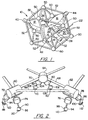
- a unitary moment control unit (MCU) 10 is shown containing four control moment gyros (CMG's) identified by reference numerals 12, 14, 16 and 18. While the structure of MCU 10 is shown as a symmetrical 14 sided structure, other configurations are possible and while CMG's are used for the preferred embodiment, other rotating mass members such as reaction wheels or momentum wheels may be used. It should also be understood, that while four CMGs have been shown, fewer may be used. Three CMGs are necessary for three axis control and the fourth CMG is for redundancy. Also more than four CMG's may be employed for fail safe and fail operational functions.
- CMG's control moment gyros
- An electronic package 20 having an input connection 22 and providing connection to each of the CMG's is shown by connectors 24, 26 28 and 30. Having the electronics co-located with the CMGs reduces the amount of electronics required and allows the unit to be tested with all of the CMG's in place.
- CMG 12 is mounted to the MCU 10 by a mounting member 40 on one end and by an unseen centrally located mounting member in a manner to be described in connection with Figure 3.
- CMG 14 is mounted to the MCU 10 by a mounting member 42 on one end and by the unseen centrally located mounting member.
- CMG 18 is mounted to the MCU 10 by a mounting member 44 on one end and by the unseen centrally located mounting member.
- CMG 16 is mounted similarly to the others by two unseen mounting members.
- the MCU is held in a rigid arrangement made up of a plurality of terminal members shown as spheres 50 and a plurality of elongated joining members 52.
- Electronics box 20 may be connected to one or more of the elongated members 52.
- the orientation of the CMG's is such that they do no lie on any axis in common.
- the torque imparted by the CMGs will be resolved into a three orthogonal axes arrangement by using vector addition of their individual torque's. In this manner the space craft to which the MCU is mounted, as will be described in connection with Figure 2, will be oriented as desired. If an CMG fails, the fourth CMG may be used to supply any missing torque.
- the mounting of the MCU 10 to the spacecraft is important in order to impart the necessary torque and to minimize emitted vibration.
- the mounting should also be kinematic to minimize strain due to temperature changes This may be accomplished by a strut type element which has relatively high stiffness along its longitudinal axis and relatively low stiffness in the other axes.
- Co-pending application of David Osterberg entitled Load Isolator apparatus filed January 29, 1997 with serial number 08/790,647 and assigned to the assignee of the present invention describes a load isolator damper arrangement which may be used.
- the number of struts used to mount the MCU is also important.
- One of the most stable ways to mount a structure is by a hexapod arrangement also known as a Stewart Platform as will be described in connection with Figure 2.
- FIG 2 a small portion of the structure of Figure 1 is shown somewhat enlarged for clarity.
- Three mounting members 60, 62 and 64 which may be members such as shown as mounting members 40 of Figure 1, are shown joined by elongated joining members 66, 68 and 70 which may be a suitable three of the joining members 52 of Figure 1.
- a hexapod mounting consisting of six struts 72, 74, 76, 78, 80 and 82 are shown.
- Struts 72 and 74 each have one end connected to mounting member 60 while their other ends are pivotally connected to pivots 84 and 86 so as to be rotatable about axes 88 and 90 respectively.
- Struts 76 and 78 each have one end connected to mounting member 62 while their other ends are pivotally connected to pivots 94 and 96 so as to be rotatable about axes 98 and 100 respectively.
- Struts 80 and 82 each have one end connected to mounting member 64 while their other ends are pivotally connected to pivots 102 and 104 so as to be rotatable about axes 106 and 108 respectively.
- Pivots 84, 86, 94, 96, 102 and 104 are each connected to the spacecraft as shown by hatched lines 110.
- Struts 72, 74, 76, 78 and 80 are designed to include a predetermined desired amount of static stiffness and passive damping.
- the passive isolation system become a mechanical low pass filter which transmits desired torque's to the spacecraft while eliminating unwanted higher frequency vibrations. Furthermore, the passive isolation system reduces structural and bearing loads during launch, reduces weight and power consumption and allows the use of smaller bearings which emit less vibration and can be operated at higher speeds while providing longer life. By tuning the spin rotor bearing mount and adding passive viscous damping at the interface, each CMG can provide damping and a measure of vibration isolation.
- an actuator can be added to each strut to provide an active isolation control capability .This can be used to lower the frequency with which isolation and torque control can be provided.
- FIG. 3 shows an octopod mounting arrangement.
- a unitary momentum control unit 120 is shown with four CMG's 122, 124, 126 and 128 mounted therein.
- CMG 122 is mounted at one end to a mounting member 130 similar to the mounting arrangement of Figure 1.
- the other end of CMG 122 is mounted to a central mounting member 134 and the spinning mass therein (not seen) rotates about an axis 138.
- CMG 124 is mounted at one end to a mounting member 140 and the other end is mounted to the central mounting member 134 and its spinning mass (not seen) rotates about an axis 144.
- CMG 126 is mounted at one end to a mounting member 150 and the other end is mounted to the central mounting member 134 and its spinning mass (not seen) rotates about an axis 154.
- CMG 128 is mounted at one end to a mounting member 160 and the other end is mounted to the central mounting member 134 and its spinning mass (not seen) rotates about an axis 164.
- the structure of MCU 120 is otherwise like the structure of MCU 10 in figure 1 and will not be described further except to note that mounting members 130, 14, 150 and 160 are mounted to the spacecraft (shown by hash marks 170) by eight struts 172 with two at each comer.
- the struts 172 may be the same as described in connection with Figure 2.
- the electronics box 20 of Figure 1 has been omitted form Figure 3 for purposes of clarity.
- the package comprising unitary MCU 10 is more spherical in general overall shape while the structure of the package of MCU 120 is more flat. Other shapes of structures may also be used so as to provide a shape best suited for the space availability of the spacecraft. It is seen that the unitary structure makes it easy for the manufacturer to test the dynamics of the system prior to mounting in the spacecraft and that a single mounting is all that is necessary to make it operational.
- the unitary structure is applicable to RW's and MW's as well as the CMG's used in the preferred embodiments. Accordingly, I do not wish to be limited to the specific structures used in connection with the preferred embodiments described herein.
Landscapes
- Engineering & Computer Science (AREA)
- Remote Sensing (AREA)
- Chemical & Material Sciences (AREA)
- Combustion & Propulsion (AREA)
- Radar, Positioning & Navigation (AREA)
- Aviation & Aerospace Engineering (AREA)
- Automation & Control Theory (AREA)
- Control Of Position, Course, Altitude, Or Attitude Of Moving Bodies (AREA)
- Vibration Prevention Devices (AREA)
- Gyroscopes (AREA)
Applications Claiming Priority (3)
| Application Number | Priority Date | Filing Date | Title |
|---|---|---|---|
| US09/139,989 US6340137B1 (en) | 1998-08-26 | 1998-08-26 | Moment control unit for spacecraft attitude control |
| PCT/US1999/017764 WO2000012269A2 (en) | 1998-08-26 | 1999-08-05 | Moment control unit for spacecraft attitude control |
| US139989 | 2002-05-07 |
Publications (2)
| Publication Number | Publication Date |
|---|---|
| EP1107852A2 EP1107852A2 (en) | 2001-06-20 |
| EP1107852B1 true EP1107852B1 (en) | 2004-01-14 |
Family
ID=22489219
Family Applications (1)
| Application Number | Title | Priority Date | Filing Date |
|---|---|---|---|
| EP99960101A Expired - Lifetime EP1107852B1 (en) | 1998-08-26 | 1999-08-05 | Moment control unit for spacecraft attitude control |
Country Status (5)
| Country | Link |
|---|---|
| US (1) | US6340137B1 (enExample) |
| EP (1) | EP1107852B1 (enExample) |
| JP (1) | JP4266520B2 (enExample) |
| DE (1) | DE69914205T2 (enExample) |
| WO (1) | WO2000012269A2 (enExample) |
Families Citing this family (20)
| Publication number | Priority date | Publication date | Assignee | Title |
|---|---|---|---|---|
| US6550721B2 (en) * | 2000-03-09 | 2003-04-22 | The Boeing Company | Safing mode for high momentum states in body stabilized spacecraft |
| US6772978B2 (en) * | 2002-02-22 | 2004-08-10 | Honeywell International Inc. | Dynamic unbalance compensation system and method |
| US7121159B2 (en) * | 2002-03-01 | 2006-10-17 | Ganid Productions, Llc | Apparatus and method for gyroscopic propulsion |
| US6891498B2 (en) * | 2002-03-28 | 2005-05-10 | Honeywell International Inc. | Inertial reference system for a spacecraft |
| US6648274B1 (en) * | 2002-04-12 | 2003-11-18 | David A. Bailey | Virtual reaction wheel array |
| US20060032985A1 (en) * | 2004-04-06 | 2006-02-16 | Monty Smith | Clutch driven reaction wheel steering unit |
| US7185855B2 (en) * | 2004-04-30 | 2007-03-06 | Honeywell International, Inc. | Method and system for steering a momentum control system |
| US7185848B2 (en) * | 2004-06-21 | 2007-03-06 | Ltas Holdings, Llc | Mass transfer system for stabilizing an airship and other vehicles subject to pitch and roll moments |
| US7014150B2 (en) * | 2004-07-30 | 2006-03-21 | Honeywell International Inc. | Method and system for optimizing torque in a CMG array |
| NL1031263C2 (nl) * | 2006-03-01 | 2007-09-04 | Univ Delft Tech | Vaartuig, bewegingsplatform, werkwijze voor het compenseren voor bewegingen van een vaartuig en gebruik van een Stewart platform. |
| US20070284502A1 (en) * | 2006-06-13 | 2007-12-13 | Nikon Corporation | Hexapod kinematic mountings for optical elements, and optical systems comprising same |
| US8020809B2 (en) * | 2007-04-18 | 2011-09-20 | Ithaco Space Systems, Inc. | Direct torque actuator control for control moment gyroscope |
| FR2924095B1 (fr) * | 2007-11-22 | 2010-02-12 | Astrium Sas | Actionneur a transfert de moment cinetique pour le controle d'attitude d'un engin spatial |
| US8312782B2 (en) * | 2009-06-18 | 2012-11-20 | Honeywell International Inc. | Control moment gyroscope based momentum control systems in small satellites |
| US20190120623A1 (en) * | 2013-03-15 | 2019-04-25 | Mario F. McGuinness | Gyroscopic balance unit, 300. and precessional propulsion method |
| CN106005483B (zh) * | 2016-07-06 | 2018-07-24 | 西北工业大学 | 一种模块化手机星的主动姿态控制方法 |
| CN110502024B (zh) * | 2019-07-23 | 2020-10-20 | 北京控制工程研究所 | 一种基于空间并联机构的准万向姿态执行机构 |
| CN110712767B (zh) * | 2019-10-29 | 2021-07-30 | 上海航天控制技术研究所 | 一种五棱锥构型控制力矩陀螺群自主重构方法 |
| CN110641739B (zh) * | 2019-11-09 | 2024-07-09 | 深圳市临近空间科技开发有限公司 | 一种多维度旋转轴连接装置 |
| CN120039426B (zh) * | 2025-02-25 | 2025-12-02 | 中国科学院微小卫星创新研究院 | 一种应用于高机动微纳卫星的混合控制构型方法 |
Family Cites Families (25)
| Publication number | Priority date | Publication date | Assignee | Title |
|---|---|---|---|---|
| US3439548A (en) * | 1966-01-28 | 1969-04-22 | Tibor Horvath | Torque generator |
| US3452948A (en) * | 1967-01-03 | 1969-07-01 | Garrett Corp | System and method for free body stabilization and orientation |
| US3493194A (en) * | 1967-07-27 | 1970-02-03 | Nasa | Spacecraft experiment pointing and attitude control system |
| US3741500A (en) * | 1971-04-21 | 1973-06-26 | Sperry Rand Corp | A cmg fine attitude control system |
| US3915416A (en) * | 1973-08-01 | 1975-10-28 | Nasa | Annular momentum control device used for stabilization of space vehicles and the like |
| US4012018A (en) * | 1973-10-04 | 1977-03-15 | The United States Of America As Represented By The Administrator Of The National Aeronautics And Space Administration | All sky pointing attitude control system |
| US3999729A (en) * | 1975-03-20 | 1976-12-28 | Rca Corporation | Backup wheel for a three axis reaction wheel spacecraft |
| US4071211A (en) * | 1976-09-23 | 1978-01-31 | Rca Corporation | Momentum biased active three-axis satellite attitude control system |
| US4230294A (en) * | 1979-07-23 | 1980-10-28 | Rca Corporation | Closed loop roll control for momentum biased satellites |
| US4375878A (en) * | 1980-10-28 | 1983-03-08 | Lockheed Missiles & Space Company, Inc. | Space satellite with agile payload orientation system |
| US4662178A (en) * | 1982-01-29 | 1987-05-05 | Rasmusson James K | Self contained rotator apparatus |
| US4723735A (en) * | 1984-12-28 | 1988-02-09 | The Charles Stark Draper Laboratory, Inc. | Energy storage attitude control and reference system |
| DE3523160A1 (de) * | 1985-06-28 | 1987-01-08 | Peter Dr Kuemmel | Kaskadenschubpraezessor |
| US4825716A (en) * | 1987-11-13 | 1989-05-02 | Honeywell, Inc. | Single gimbal control moment gyroscope skewed array mounting arrangement |
| EP0381726A4 (en) * | 1988-05-27 | 1992-08-19 | Honeywell Inc. | Skewed axis inertial sensor assembly |
| US5058835A (en) * | 1990-06-11 | 1991-10-22 | General Electric Company | Wheel speed management control system for spacecraft |
| FR2670746B1 (fr) * | 1990-12-21 | 1993-04-16 | Aerospatiale | Systeme de controle d'attitude pour satellite 3-axes,; notamment pour satellite d'observation. |
| US5305981A (en) * | 1991-10-31 | 1994-04-26 | Honeywell Inc. | Multiaxis vibration isolation system |
| US5820079A (en) * | 1994-04-05 | 1998-10-13 | Hughes Electronics | Mechanism for mounting and actuating a momentum wheel with high vibration isolation |
| US5476239A (en) * | 1994-04-19 | 1995-12-19 | The United States Of America As Represented By The Secretary Of The Navy | Gyro platform assembly with a spinning vehicle |
| US5611505A (en) * | 1994-11-18 | 1997-03-18 | Hughes Electronics | Spacecraft energy storage, attitude steering and momentum management system |
| US5820078A (en) * | 1996-09-27 | 1998-10-13 | Hughes Electronics Corporation | Control motion gyro with vibration isolation |
| US6022005A (en) * | 1996-09-27 | 2000-02-08 | Trw Inc. | Semi-active vibration isolator and fine positioning mount |
| US5918865A (en) | 1997-01-29 | 1999-07-06 | Honeywell Inc. | Load isolator apparatus |
| US6089508A (en) * | 1998-03-02 | 2000-07-18 | Hughes Electronics Corporation | Autonomous spacecraft safing with reaction wheels |
-
1998
- 1998-08-26 US US09/139,989 patent/US6340137B1/en not_active Expired - Lifetime
-
1999
- 1999-08-05 DE DE69914205T patent/DE69914205T2/de not_active Expired - Lifetime
- 1999-08-05 EP EP99960101A patent/EP1107852B1/en not_active Expired - Lifetime
- 1999-08-05 JP JP2000567353A patent/JP4266520B2/ja not_active Expired - Fee Related
- 1999-08-05 WO PCT/US1999/017764 patent/WO2000012269A2/en not_active Ceased
Also Published As
| Publication number | Publication date |
|---|---|
| JP2002523291A (ja) | 2002-07-30 |
| WO2000012269A2 (en) | 2000-03-09 |
| DE69914205T2 (de) | 2004-11-25 |
| EP1107852A2 (en) | 2001-06-20 |
| US6340137B1 (en) | 2002-01-22 |
| WO2000012269A3 (en) | 2000-06-02 |
| DE69914205D1 (de) | 2004-02-19 |
| JP4266520B2 (ja) | 2009-05-20 |
Similar Documents
| Publication | Publication Date | Title |
|---|---|---|
| EP1107852B1 (en) | Moment control unit for spacecraft attitude control | |
| Anderson et al. | Satellite ultraquiet isolation technology experiment (SUITE) | |
| US5638303A (en) | Non-contacting isolated stabilized microgravity platform system | |
| JP2017508109A (ja) | プラットフォーム安定化システム | |
| US5419528A (en) | Vibration isolation mounting system | |
| Agrawal et al. | Air-bearing-based satellite attitude dynamics simulator for control software research and development | |
| Gaude et al. | Design and structural analysis of a control moment gyroscope (CMG) actuator for cubeSats | |
| CN114740757B (zh) | 磁悬浮非对称旋转扫描卫星的两体姿态仿真方法和系统 | |
| Tyc et al. | Gyrowheel™-An Innovative New Actuator/Sensor for 3-axis Spacecraft Attitude Control | |
| CN118462602A (zh) | 一种基于双级磁悬浮超平台的微振动“泵排”控制方法 | |
| McLallin et al. | Aerospace flywheel technology development for IPACS applications | |
| Bushnell et al. | Active rack isolation system development for the International Space Station | |
| Wilson et al. | Viscous damped space structure for reduced jitter | |
| McChesney | Design of attitude control actuators for a simulated spacecraft | |
| Nye et al. | Performance of active vibration control technology: the ACTEX flight experiments | |
| Maly et al. | ESPA: EELV Secondary Payload Adapter with whole-spacecraft isolation for primary and secondary payloads | |
| Jacobs et al. | Miniature vibration isolation system for space applications: Phase II | |
| Kondo | Integration of a fiber optic gyro AHRS into a fly-by-light aircraft configuration | |
| Beader | Application of Roll-isolated Inertial Measurement Units to the Instrumentation of Spinning Vehicles | |
| Wong et al. | A pointing system design concept for space station attached payloads | |
| You et al. | Development of Modular Variable Speed Control Moment Gyro in a miniature Cube | |
| Keckler et al. | A system for load isolation and precision pointing | |
| Rybak et al. | Ultrahigh-accuracy body-pointing system for the Large Space Telescope | |
| US20090120217A1 (en) | Rotor assemblies with adjustable struts | |
| Kormanik | Integration and test of a fiber optic gyro AHRS into a fly-by-light aircraft configuration |
Legal Events
| Date | Code | Title | Description |
|---|---|---|---|
| PUAI | Public reference made under article 153(3) epc to a published international application that has entered the european phase |
Free format text: ORIGINAL CODE: 0009012 |
|
| 17P | Request for examination filed |
Effective date: 20010226 |
|
| AK | Designated contracting states |
Kind code of ref document: A2 Designated state(s): AT BE CH CY DE DK ES FI FR GB GR IE IT LI LU MC NL PT SE Kind code of ref document: A2 Designated state(s): DE FR GB IT |
|
| RIC1 | Information provided on ipc code assigned before grant |
Free format text: 7B 64G 1/28 A, 7G 05D 1/08 B |
|
| RIC1 | Information provided on ipc code assigned before grant |
Ipc: 7G 05D 1/08 B Ipc: 7B 64G 1/28 A |
|
| GRAP | Despatch of communication of intention to grant a patent |
Free format text: ORIGINAL CODE: EPIDOSNIGR1 |
|
| GRAS | Grant fee paid |
Free format text: ORIGINAL CODE: EPIDOSNIGR3 |
|
| GRAA | (expected) grant |
Free format text: ORIGINAL CODE: 0009210 |
|
| AK | Designated contracting states |
Kind code of ref document: B1 Designated state(s): DE FR GB IT |
|
| REG | Reference to a national code |
Ref country code: GB Ref legal event code: FG4D |
|
| REF | Corresponds to: |
Ref document number: 69914205 Country of ref document: DE Date of ref document: 20040219 Kind code of ref document: P |
|
| ET | Fr: translation filed | ||
| PLBE | No opposition filed within time limit |
Free format text: ORIGINAL CODE: 0009261 |
|
| STAA | Information on the status of an ep patent application or granted ep patent |
Free format text: STATUS: NO OPPOSITION FILED WITHIN TIME LIMIT |
|
| 26N | No opposition filed |
Effective date: 20041015 |
|
| PGFP | Annual fee paid to national office [announced via postgrant information from national office to epo] |
Ref country code: IT Payment date: 20100812 Year of fee payment: 12 |
|
| PGFP | Annual fee paid to national office [announced via postgrant information from national office to epo] |
Ref country code: GB Payment date: 20100708 Year of fee payment: 12 |
|
| GBPC | Gb: european patent ceased through non-payment of renewal fee |
Effective date: 20110805 |
|
| PG25 | Lapsed in a contracting state [announced via postgrant information from national office to epo] |
Ref country code: IT Free format text: LAPSE BECAUSE OF NON-PAYMENT OF DUE FEES Effective date: 20110805 |
|
| PG25 | Lapsed in a contracting state [announced via postgrant information from national office to epo] |
Ref country code: GB Free format text: LAPSE BECAUSE OF NON-PAYMENT OF DUE FEES Effective date: 20110805 |
|
| PGFP | Annual fee paid to national office [announced via postgrant information from national office to epo] |
Ref country code: DE Payment date: 20130902 Year of fee payment: 15 |
|
| PGFP | Annual fee paid to national office [announced via postgrant information from national office to epo] |
Ref country code: FR Payment date: 20130725 Year of fee payment: 15 |
|
| REG | Reference to a national code |
Ref country code: DE Ref legal event code: R119 Ref document number: 69914205 Country of ref document: DE |
|
| REG | Reference to a national code |
Ref country code: FR Ref legal event code: ST Effective date: 20150430 |
|
| REG | Reference to a national code |
Ref country code: DE Ref legal event code: R119 Ref document number: 69914205 Country of ref document: DE Effective date: 20150303 |
|
| PG25 | Lapsed in a contracting state [announced via postgrant information from national office to epo] |
Ref country code: DE Free format text: LAPSE BECAUSE OF NON-PAYMENT OF DUE FEES Effective date: 20150303 |
|
| PG25 | Lapsed in a contracting state [announced via postgrant information from national office to epo] |
Ref country code: FR Free format text: LAPSE BECAUSE OF NON-PAYMENT OF DUE FEES Effective date: 20140901 |
|
| P01 | Opt-out of the competence of the unified patent court (upc) registered |
Effective date: 20230525 |