EP1107625A1 - Dialog zwischen zwei Steuereinheiten, insbesondere in einem Dual-Mode DECT/GSM Mobilfunk-Endgerät - Google Patents
Dialog zwischen zwei Steuereinheiten, insbesondere in einem Dual-Mode DECT/GSM Mobilfunk-Endgerät Download PDFInfo
- Publication number
- EP1107625A1 EP1107625A1 EP00403072A EP00403072A EP1107625A1 EP 1107625 A1 EP1107625 A1 EP 1107625A1 EP 00403072 A EP00403072 A EP 00403072A EP 00403072 A EP00403072 A EP 00403072A EP 1107625 A1 EP1107625 A1 EP 1107625A1
- Authority
- EP
- European Patent Office
- Prior art keywords
- controller
- microcontroller
- terminal
- wire
- data
- Prior art date
- Legal status (The legal status is an assumption and is not a legal conclusion. Google has not performed a legal analysis and makes no representation as to the accuracy of the status listed.)
- Granted
Links
Images


Classifications
-
- H—ELECTRICITY
- H04—ELECTRIC COMMUNICATION TECHNIQUE
- H04W—WIRELESS COMMUNICATION NETWORKS
- H04W88/00—Devices specially adapted for wireless communication networks, e.g. terminals, base stations or access point devices
- H04W88/02—Terminal devices
- H04W88/06—Terminal devices adapted for operation in multiple networks or having at least two operational modes, e.g. multi-mode terminals
Definitions
- the present invention relates to a dialogue between two controllers.
- a first controller is master and transmits first units of protocol data to a second controller who is a slave to the first controller and responds to the first units with second protocol data units.
- the second controller the slave, cannot transmit data that in response to a command from the first controller.
- such a dialogue is established between the microcontroller in a smart card and the microcontroller of a card reception means.
- the smart card is a SIM card (Subscriber Identity Module) and the means of reception is a mobile radiotelephone terminal.
- SIM card Subscriber Identity Module
- the microcontrollers in the SIM card and the terminal interact according to a data exchange protocol asynchronous known as "SIM application Toolkit "which allows the card to trigger actions in the terminal.
- the microcontroller in the terminal is still the master of the rhythm of the exchanges. So that the microcontroller in the card can undertake an action, the terminal periodically interrogates (polling in English) the pro-active SIM card using a STATUS command, in particular to invite the card to trigger an action.
- the reaction speed of the microcontroller in the card then depends on the periodicity interrogation of the microcontroller in the terminal and so does not allow the card microcontroller to launch an action as soon as it is necessary.
- the main objective of the invention is to provide a method of dialogue between two controllers master and slave type as defined above not having the above drawback.
- a process of dialogue according to which a first controller transmits first units data to which a second controller responds by second data units is characterized by a first logical state change of a first wire between the controllers made by the second controller when the latter decides to send a command to the first controller, a transmission of a first unit of data predetermined by the first controller following the first change state, and a second logical state change of the first thread opposed to the first change and the transmission of a second data unit performed by the second controller to respond to the predetermined order.
- the first logical state change from the first wire, or any other connecting means between the two controllers, is taken on the initiative of the second controller, the controller who was a "slave", can thus react immediately, for example to a external event, without waiting for periodic sending of a first particular data unit by the first controller.
- the outdoor event can be an incoming call from the second controller when this one is dedicated to communications management and want to immediately use peripheral means managed by the first controller.
- the predetermined data unit succeeding the first logical state change differs from classic STATUS command and is, according to a preferred embodiment, an envelope containing a empty data field.
- a proactive control can be launched from the second controller before a command-response sequence session be completed, which is impossible in a session between a SIM card and a terminal according to the technique anterior.
- very first data unit transmitted by the first controller between first and second state changes of first wire is ignored by the second controller when the latter decides to send an order to first controller while a dialogue session is in progress between controllers.
- the present invention also pursues a second objective to reduce consumption the second controller which, according to the prior art, is active even between two successive interrogations by the first controller.
- the invention provides for maintaining a first logical state of a second wire between controllers by the first controller only during each exchange of first and second data units, so that the second controller selected by the first controller is active only during exchange.
- the second controller is on standby and so works with power consumption reduced when the second wire is at a second logical state between two successive exchanges of first and second data units, i.e. command-response sequences.
- the invention also provides for maintaining a third wire between controllers to a first state logic by the first controller to put out voltage the second controller following a first predetermined data unit established by the first controller, and / or in response to a second predetermined data unit established by the second controller.
- the second controller is powered off when the first controller is at a first mode of operation exclusive of any relationship with the second controller. This characteristic further decreases the power consumption of the second controller during periods of operation of the first controller for which the first controller has no use.
- the first and second controllers are included in a radiotelephone terminal and dedicated first and second modes respectively communication so that the first controller puts on layout of the second controller an interface man-machine.
- the human-machine interface can include a display and a keyboard used regardless of the communication mode selected, for example the GSM mode to which is dedicated the first controller and the DECT mode to which dedicated the second controller, or vice versa.
- the radiotelephone terminal of the invention is as compact as those according to the prior art.
- the first controller and human-machine interface are contained in a first block
- the second controller and a means of power supply the controllers are contained in a second nestable block in the first block.
- a dual mode mobile terminal DMT (Dual Mode Terminal) is capable of communicating in a first mode of communication called GSM (Global System for Mobile communication) or in a second mode of communication called DECT (Digital Enhanced Cordless Telecommunications).
- GSM Global System for Mobile communication
- DECT Digital Enhanced Cordless Telecommunications
- the first GSM mode indifferently designates a communication with a RR radiotelephone network of GSM 900 type or of DCS 1800 (Digital Cellular System) type, the fixed sub-network of which is shown diagrammatically in FIG. 1.
- the terminal DMT When the terminal DMT communicates in DECT mode, it exchanges signals through a radio terminal BR which is connected to a switch CM of a fixed telephone network RT such as the public telephone network or a digital network with integration of ISDN services through a subscriber telephone line and possibly through a PABX private switch.
- the BR terminal notably serves other portable telephone terminals operating at least in DECT mode.
- the DMT dual mode mobile radiotelephone terminal includes a first part BG mainly dedicated to communications according to the first GSM mode and a second BD section dedicated to communications according to the second DECT mode.
- these two parts BG and BD can be contained in the same box terminal, these parts according to the illustrated embodiment in Figure 1 are completely separate and separated and contained respectively in a case hereinafter called GSM BG block and a case hereinafter called DECT BD block linked together by a triple LC-LA-LB electrical contact connection.
- the BD block dedicated to DECT communications is contained in the block of removable BA battery of a radiotelephone terminal classic GSM including the case with the keyboard constitute the block BG.
- connection between blocks BG and BD is supplemented by an LC link between microcontrollers and an LA audio link between audio interfaces.
- LA, LB and LC connections are made up of three wires, four sons and five sons, each "thread" being in practice consisting of two conductive tapes extending respectively in the blocks and whose ends come into contact when the BD block is fixed by nesting in the rear face of the BG block.
- Each block BG, BD is organized around a respective microcontroller CG, CD which includes conventionally a microprocessor, a ROM memory and a RAM memory which manages communications according to the first GSM mode, respectively the second mode DECT as in a radiotelephone terminal of the type GSM, DECT type respectively.
- Each microcontroller CG, CD controls an audio interface AG, AD mainly comprising a speech coding and decoding circuit and a radio interface RG, RD mainly comprising a modulator and a demodulator, analog-digital and digital-analog converters, circuits for frequency transposition and a duplexer for transmission and reception channels.
- the AG and AD audio interfaces are connected by the LA bond comprising a ground wire M, a analog audio signal transmission AUT and one wire AUR analog audio reception.
- the AUT wire transmits an audio signal from the user of the terminal from MI microphone from AG interface to the AD interface, and the AUR wire receives a signal audio of a remote party from the interface AD to an EC listener connected to the AG interface.
- the AG audio interface manages volume and echo cancellation and ignore the AD interface.
- AD audio interface handles requests for adjustment of volume after pressing VM keyboard keys and VP and echo cancellation via command-response pairs between microcontrollers CG and CD, as if the audio interface AD is connected directly to the MI microphone and to the EC earphone at through the AG audio interface that has become transparent.
- the RG and RD radio interfaces operate under the respective commands of the CG and CD microcontroller according to GSM and DECT communication protocols and are thus independent.
- the first BG block dedicated to communications according to first GSM mode makes available to the second BD block a man-machine interface comprising a AF liquid crystal display, CL keyboard, BU buzzer and a personal SIM card (Suscriber Identity Module).
- BU buzzer reproduced ringing melodies especially for various types call.
- the melodies are initially chosen by the user and are selected in part by the CG microcontroller for mode communications GSM and partly by the CD microcontroller for communications in DECT mode.
- the SIM card is removable from the BG block and mainly contains a microcontroller with communication algorithms and specific application and profile of subscription of the user owner of the card SIM.
- the four elements AF, CL, BU and SIM are managed by the CG microcontroller naturally for a GSM type communication and indirectly from CD microcontroller for type communication DECT.
- the AF display is connected to the CG and CD microcontrollers through two wires TX and RX to exchange commands and responses between the microcontrollers, as will be seen below.
- the CD microcontroller manages menus for DECT communication displayed on the AF display with characters accepted by the commands exchanged between the SIM card and the CG microcontroller known as the SIM Application Toolkit.
- the characteristics of the AF display are exchanged between the microcontrollers CG and CD during the initialization of the microcontroller CD by the microcontroller CG, when the DMT terminal is powered up.
- the microcontroller CD does not directly manage the graphic display and takes into account the characteristics of the AF display to center messages on the display screen.
- the microcontroller CD signals to the BR terminal (DECT base) the characteristics of the display in accordance with the DECT communication protocol.
- the microcontroller CG relating to the GSM communication mode manages the cursors and the icons as well as any event which could interrupt a display.
- the microcontroller CD displays on the AF display through the microcontroller CG an identifier, such as name, of the radio terminal BR that the user of the DMT terminal assigned when the latter declared himself to the BR terminal according to a procedure known for DECT mode.
- the identifier of the BR terminal as well as the identifier, such as the name, of the operator of the RR radiotelephony network for GSM mode are displayed at the start of a main menu, in particular after switching on the terminal by requesting a power-on key and dialing a confidential code on the CL keyboard, or after waking up the terminal, or after returning to the main menu.
- this presents the conventional dialing keyboard with twelve keys CL and several additional keys specified below, according to a known embodiment of a GSM mobile radiotelephone terminal.
- the additional keys are an on-hook key TR, for example red; a line hold key TP, for example green; a "central navigation key” comprising on the left and right an erasing key C (Clear), an OK validation key and elevator keys with up arrow FH and down arrow FB; and two buttons for adjusting the sound volume of the earpiece, a button for decreasing the volume VM and a button for increasing the volume VP located below the screen of the AF display and respectively substantially above the buttons TR and TP .
- the user dials the number telephone of the called party before pressing the key TP line socket, in accordance with the establishment an outgoing call in GSM mode, and unlike a outgoing call in DECT mode.
- the TP key triggers the establishment of a radio communication with the BTS base station to which the DMT terminal momentarily when this one works in GSM mode, or radio communication with the BR terminal in-the cover of which the DMT terminal is momentarily located.
- Two additional keys TG and TD which are programmable according to the invention and which are set the disposition of a user of a DECT terminal appear at the bottom of the AF display screen in response to a request from the arrow key towards the high FH when a communication in DECT mode is established by the DMT terminal.
- Relative to the right soft key TD successive presses on the FH and VP keys are equivalent to an intercom button in a classic DECT terminal. If the user continues to navigate the menus, the two keys programmable TG and TD disappear from the display AF when the user presses another key, for example example for consulting a menu with the FH and FB.
- the DMT terminal has three possible configurations which are a configuration in DECT mode only, a configuration in GSM mode only, and an automatic dual mode configuration. One of these three configurations is selected prior to any communication in a "SETTINGS / NETWORK" menu using the FH, FB and OK keys. If the configuration in DECT mode is selected, the DMT terminal operates only in DECT mode and the radio interface RG is cut off from the radiotelephony network RR and the terminal behaves like a mobile terminal of DECT type; in this DECT mode, the terminal receives external incoming or intercom calls in DECT mode and establishes outgoing calls in DECT mode.
- the radio interface RD is cut off from the radio terminal BR and the terminal DMT behaves like a mobile terminal of GSM type; in this GSM mode, the terminal receives incoming GSM traffic or SMS short message calls and establishes outgoing calls in GSM mode.
- the DMT terminal can automatically switch between GSM and DECT modes due to a loss of coverage or service relating to one of the two communication modes; in this dual-mode configuration, the DMT terminal maintains its location with respect to the base station BTS and the radio terminal BR insofar as it is under the coverage of these.
- radio interface means that the transmission medium included in this interface does not emit, i.e. is off, so as not to disturb the operation of reception means in the interface radio associated with the other mode of communication; through example, when the first mode of communication is selected to establish communication with a DCS 1800 radiotelephony network, the medium in the DECT RD radio interface, the transmit frequency band is very close to the frequency band of the DCS 1800 network is cut at least during mode communications GSM. Alternatively, in order to decrease consumption electrical terminal, radio interface corresponding to the unselected DECT or GSM mode is completely cut off during a call according to the other mode.
- the battery BA of the terminal DMT included in the removable block BD is entirely managed by the microcontroller CG.
- the LB link comprises in a known manner a pair of TP and TM wires connected to the terminals of a TH thermistor in the BD block and a pair of wires BP and BM connected to the BA battery terminals in the BD block to supply the circuits in the BC block.
- the second CD microcontroller and the AD and RD interfaces are also powered by the BA battery but under the control of the first CG microcontroller as explained below.
- the LC link between the microcontrollers CG and CD comprises a first wire, said interrupt wire INT, a second wire, said second controller selection wire CS, a second block ON-off wire ON, and two transmission wires and TX and RX protocol data unit reception.
- the TX and RX wires are asynchronous serial links having a standardized bit rate between 4800 and 38400 bauds with bytes representative of characters comprising a stop bit, without parity bit.
- the TX and RX wires respectively for COM commands and RES responses are multiplexed with data wires from the AF display.
- the first microcontroller CG transmits application protocol data APDU (Application Protocol Data Unit) of COM command to the second microcontroller CD through the transmission wire TX.
- the second microcontroller CD transmits response response application protocol data units APDU RES to the microcontroller CG through the reception wire RX.
- APDU Application Protocol Data Unit
- the two transmission wires of TX and RX data are replaced by a single wire for an exchange of data units in the work-study program (half-duplex) between the microcontrollers.
- Command-response sequences are sequences of data units according to the communication of the invention analogous to that of the communication protocol for asynchronous work-study character by character or block of characters by block of characters, grouped under the term SIM Application Toolkit according to the standard for smart cards ISO 7816-3 / 4, i.e. according to the protocol between the first CG microcontroller and the SIM card.
- the second CD microcontroller is the slave of the first CG microcontroller, master.
- the first CG microcontroller brings the layout of the second CD microcontroller the AF, CL, SIM, BU, MI and EC elements as if the second CD microcontroller was connected directly to these, the first CG microcontroller ignoring completely the characteristics of the protocol of communication in the second DECT mode.
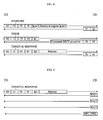
- a COM command with a header with five bytes whether or not followed by a data field
- a RES response starting-possibly with a field of data followed by two status bytes SW1 and SW2
- a WAIT wait comprising a single byte '60'.
- the bytes indicated between two accents or between square brackets are expressed in code hexadecimal.
- the first CLA byte designates an instruction class contained in the next byte
- the INS byte is a instruction code linked to a system command operating the second microcontroller CD
- P1, P2 and P3 are parameters relating to instruction.
- the first two parameters P1 and P2 are at '00'.
- Parameter P3 indicates the length lg expressed in bytes of the command data field COM when it exists. However, the setting P3 can indicate the length of data requested by a response of type [91, lg1] for data to forward in a next type response [90, 00].
- FIG. 3A relates to a pair of command-response without the CD microcontroller retransmits data.
- FIG. 3B relates to data transmission from the CG microcontroller to the CD microcontroller with data transmission from length lg1 by the CD microcontroller.
- Figure 3C relates to sending data of length lg by the microcontroller CD to the microcontroller CG at the following an empty DATA ENVELOPE command with the zero length '00'.
- the CLA class byte is always equal to 'A0'
- the instruction byte INS has three values.
- the value '14' of the INS byte indicates a TERMINAL RESPONSE type instruction for transmit the response from the CG microcontroller to the other CD microcontroller following a command proactive contained in a RES response of type "DECT command”.
- the value '12' of the INS byte denotes a FETCH instruction which, following a type response [91, lg], prompt second CD microcontroller to transfer RES response with a data field containing an order, by example relating to a ringing call or the display of a DECT menu.
- the 'C2' value of the byte INS means an ENVELOPE instruction to transfer data from the first CG microcontroller to the second CD microcontroller when parameter P3 is equal to the length lg of the data field of the ENVELOPE command as shown in Figure 3B, or to allow the second CD microcontroller send a proactive order request with the answer [91, lg] in connection with setting logic "1" of an INT interrupt wire in the LC bond, as will be seen later, when parameter P3 is equal to '00' as shown in the Figure 3C.
- the ENVELOPE statement with a data field having a length other than 0 allows the CG microcontroller to send to CD microcontroller for example a "DECT command", a "command from call control "or a” test command ".
- the TERMINAL RESPONSE instruction responds to a response containing a DECT command. Any DECT command included in a RES response established by CD microcontroller results from the exchange shown in the Figure 4 successively including a command ENVELOPE of length lg or 0, a response [91, lg1], a FETCH command [lg1], a command response Proactive DECT [90, 00], a TERMINAL command RESPONSE [lg2] and an acknowledgment response [9x, xx].
- a COM command such as ENVELOPE, FETCH, or TERMINAL RESPONSE
- the Figure 5 illustrates an example of three units successive WAIT pending response [SW1, SW2] to a TERMINAL RESPONSE command.
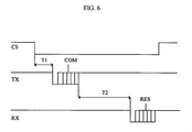
- the second microcontroller selection wire CS (Chip Select) in the LC link between microcontrollers has a first low logic state "0" maintained by the microcontroller CG dedicated to DECT communications during each transmission / reception sequence between the two microcontrollers CG and CD, that is to say during the exchange of a COM command and a RES response as shown in FIG. 6.
- the wire CS is maintained in the second high logic state "1" by the microcontroller CG so that any exchange between the CG and CD microcontrollers is prohibited and the CD microcontroller is in standby state with reduced power consumption, the CG microcontroller can then communicate with the man-machine interface with regard to data excluding DECT mode.
- the microcontroller CG After receiving the RES response, the microcontroller CG sets the CS wire to "1" if no other COM command is transmitted afterwards of the RES response so as to "sleep" the CD microcontroller and thus reduce consumption of energy from it.
- the transition from state “0" to state “1" of the CS wire normally after a response RES, or by mistake during the exchange of a COM command and RES response causes termination immediate order / response sequence and delivery to zero of the data in reception and transmission in the CD microcontroller.
- the CG microcontroller When the CG microcontroller does not receive response at the end of T2 (time-out), or when the CG microcontroller does not understand the RES response sent to him, he stops immediately exchange passing the CS wire of state "0" to state "1", then toggles the state of the wire CS at "0" and re-issues the COM command on the TX wire after a T1 guard time. This re-broadcast may be launched up to three trials. If these three attempts fail, the CG microcontroller abandons the exchange. If it is an ENVELOPE or TERMINAL instruction RESPONSE, the CG microcontroller indicates to the user on the AF display "BD block absent". This principle applies to ENVELOPE instructions of length no null and FETCH instructions, but not ENVELOPE instructions of zero length.
- CG microcontroller numbers COM commands made up of an ENVELOPE of non-zero length. Two successive orders have numbers so that the CG microcontroller differentiates a new command of a repeated command. Through therefore, when the CD microcontroller receives two successive orders containing the same number, it does not ignore the second command and respond with a RES response.
- the second CD microcontroller makes a first logical change of state of the wire INT interrupt, when the CD microcontroller wakes up and intends to send data or a proactive command to the CG microcontroller or to interrogate it.
- the CD microcontroller performs a first change of the high logic state "1" in the low logic state "0" of the INT wire.
- the CD microcontroller performs a second state change of the INT wire from state "0" to state "1".
- the CD microcontroller can relaunch this request three consecutive times. If the third ENVELOPE command request length null fails, CD microcontroller resets according to a first variant, or abandons the request of order in progress according to a second variant, or continues the order request attempts according to a third variant.
- the CD microcontroller positions the INT wire in the state "0". For example, as shown in Figure 8, the CD microcontroller order request intervenes during the choice in a menu relating to DECT mode, after a FETCH command, a response invitation to use the CL keyboard [GET INKEY, 90, 00], pressing a key on the CL keyboard and waiting by the CD microcontroller until the user has choose the menu.
- the microcontroller CD sets to "0" the INT wire which causes the session to be abandoned (menu in progress) by the CG microcontroller which returns to the rest.
- the microcontroller CG transmits the TERMINAL command RESPONSE to the microcontroller CD with the result "session abandoned”.
- the CD microcontroller then puts at "1" the interrupt wire INT and sends a response [91, lg] to start another session specific to the establishment of the incoming call.
- This session begins with a FETCH command transmitted by the CG microcontroller and then a incoming call establishment response [SETUP, 90, 00] so as to trigger the BU buzzer with a ring signal.
- the DMT terminal can work exclusively in GSM or DECT mode, in prohibiting any communication through the interface relating to the other mode of communication so avoid mutual disruption between RG and RD radio interfaces in the DMT terminal.
- the CG microcontroller no longer has need for exclusivity, following the end of a GSM communication, it ends this by a RADIO STATUS command.
- the CG microcontroller goes radio exclusive in DECT mode.
- the hold key TP line which also serves as a Redial key for redial of the last telephone number and key amplified listening is also requested for turn on the terminal, i.e. to turn on the battery included in the BD removable block, electronic circuits of terminal, such as CG and CD microcontrollers.
- the hang up key TR also serves to stop button to de-energize circuits electronic in the BG and BD blocks of the terminal when the latter is no longer in communication.
- the third wire ON in the LC link between the microcontrollers CG and CD also serves to control the stop, that is to say to turn off the power, and to start up, that is to say to be energized, from the second block BD by the microcontroller CG.
- stopping the BD block while the DMT terminal is in GSM mode reduces the power consumption of the DMT terminal.
- the CG microcontroller When the CG microcontroller wishes radio exclusivity for mode communication GSM as shown in figure 9, it sends a envelope with a stop instruction [SHUTDOWN] at CD microcontroller which establishes a response [90, 00] to following which, the CD microcontroller launches stopping all applications and radio communications in progress.
- the CD microcontroller When the CD microcontroller is ready, it sends to the microcontroller CG a stop request according to the sequence described below with reference to the figure 10, as a result of which the microcontroller CG puts in logic low state "0" the wire ON to cut the power supply mainly from the CD microcontroller by BA battery.
- an exchange according to the invention is established as shown in the figure 10, with an ENVELOPE command of zero length, a response [91, xx], a FETCH command, and a response DECT command button [OFF, 90, 00] so that the CD microcontroller asks the CG microcontroller to switch off the BD block battery voltage setting the wire ON to "0".
- This ON wire zeroing of the BD block by the CG microcontroller to cut the BD block supply can precede the transmission a TERMINAL RESPONSE command which is ignored by the CD microcontroller.
- the terminal reboots in dual mode automatic. If the DMT terminal is in another mode than DECT mode, the CG microcontroller tells the CD microcontroller after the CD microcontroller be turned on again by switching the ON wire from state "0" to state "1" by the CG microcontroller followed by a procedure exchange similar to that of Figure 9, in replacing the OFF response with an ON response such as shown in Figure 10. Then, the microcontroller CG can send a COM [SELECT] command to qualify to the CD microcontroller the radio terminal which was in radio link with the RD interface.
Landscapes
- Engineering & Computer Science (AREA)
- Computer Networks & Wireless Communication (AREA)
- Signal Processing (AREA)
- Mobile Radio Communication Systems (AREA)
Applications Claiming Priority (2)
| Application Number | Priority Date | Filing Date | Title |
|---|---|---|---|
| FR9915232A FR2802050B1 (fr) | 1999-12-01 | 1999-12-01 | Dialogue entre deux controleurs notamment dans un terminal radiotelephonique bimode dect/gsm |
| FR9915232 | 1999-12-01 |
Publications (3)
| Publication Number | Publication Date |
|---|---|
| EP1107625A1 true EP1107625A1 (de) | 2001-06-13 |
| EP1107625B1 EP1107625B1 (de) | 2005-04-06 |
| EP1107625B8 EP1107625B8 (de) | 2005-06-01 |
Family
ID=9552830
Family Applications (1)
| Application Number | Title | Priority Date | Filing Date |
|---|---|---|---|
| EP20000403072 Expired - Lifetime EP1107625B8 (de) | 1999-12-01 | 2000-11-06 | Dialog zwischen zwei Steuereinheiten, insbesondere in einem Dual-Mode DECT/GSM Mobilfunk-Endgerät |
Country Status (4)
| Country | Link |
|---|---|
| EP (1) | EP1107625B8 (de) |
| DE (1) | DE60019242T2 (de) |
| ES (1) | ES2235803T3 (de) |
| FR (1) | FR2802050B1 (de) |
Cited By (1)
| Publication number | Priority date | Publication date | Assignee | Title |
|---|---|---|---|---|
| WO2007059722A1 (de) * | 2005-11-28 | 2007-05-31 | Winrich Hoseit | Dect-telefon und system für dect-telefonie |
Families Citing this family (1)
| Publication number | Priority date | Publication date | Assignee | Title |
|---|---|---|---|---|
| DE102017007792A1 (de) * | 2017-08-18 | 2019-02-21 | Ulrich Berger | Anordnung mit einem Mobilfunk fähigen Gerät und einem Verbindungsgerät |
Citations (5)
| Publication number | Priority date | Publication date | Assignee | Title |
|---|---|---|---|---|
| DE4118993A1 (de) * | 1991-06-08 | 1992-12-10 | Aeg Mobile Communication | Mobiltelefonanordnung |
| WO1998009462A1 (en) * | 1996-08-30 | 1998-03-05 | Ericsson Inc. | Multi-mode mobile station supporting multiple cellular telephone system operation with limited subscriber identity module card |
| WO1998027766A2 (de) * | 1996-12-19 | 1998-06-25 | Siemens Aktiengesellschaft | Verfahren und vorrichtung zur reduktion des stromverbrauchs in mobilen multimode-kommunikationsendgeräten |
| EP0858237A2 (de) * | 1997-02-05 | 1998-08-12 | Nokia Mobile Phones Ltd. | Intelligente Netzwerksuche für ein Multimoden-Telefon |
| DE19914254A1 (de) * | 1999-03-29 | 1999-07-29 | Kunze Ingeburg | Verfahren zum Aufbauen einer Telefonverbindung mit einem Dual-Mode-Mobilfunktelefon für GSM- und DECT-Betrieb |
-
1999
- 1999-12-01 FR FR9915232A patent/FR2802050B1/fr not_active Expired - Lifetime
-
2000
- 2000-11-06 ES ES00403072T patent/ES2235803T3/es not_active Expired - Lifetime
- 2000-11-06 DE DE2000619242 patent/DE60019242T2/de not_active Expired - Lifetime
- 2000-11-06 EP EP20000403072 patent/EP1107625B8/de not_active Expired - Lifetime
Patent Citations (5)
| Publication number | Priority date | Publication date | Assignee | Title |
|---|---|---|---|---|
| DE4118993A1 (de) * | 1991-06-08 | 1992-12-10 | Aeg Mobile Communication | Mobiltelefonanordnung |
| WO1998009462A1 (en) * | 1996-08-30 | 1998-03-05 | Ericsson Inc. | Multi-mode mobile station supporting multiple cellular telephone system operation with limited subscriber identity module card |
| WO1998027766A2 (de) * | 1996-12-19 | 1998-06-25 | Siemens Aktiengesellschaft | Verfahren und vorrichtung zur reduktion des stromverbrauchs in mobilen multimode-kommunikationsendgeräten |
| EP0858237A2 (de) * | 1997-02-05 | 1998-08-12 | Nokia Mobile Phones Ltd. | Intelligente Netzwerksuche für ein Multimoden-Telefon |
| DE19914254A1 (de) * | 1999-03-29 | 1999-07-29 | Kunze Ingeburg | Verfahren zum Aufbauen einer Telefonverbindung mit einem Dual-Mode-Mobilfunktelefon für GSM- und DECT-Betrieb |
Cited By (1)
| Publication number | Priority date | Publication date | Assignee | Title |
|---|---|---|---|---|
| WO2007059722A1 (de) * | 2005-11-28 | 2007-05-31 | Winrich Hoseit | Dect-telefon und system für dect-telefonie |
Also Published As
| Publication number | Publication date |
|---|---|
| EP1107625B8 (de) | 2005-06-01 |
| FR2802050B1 (fr) | 2002-01-11 |
| EP1107625B1 (de) | 2005-04-06 |
| FR2802050A1 (fr) | 2001-06-08 |
| DE60019242D1 (de) | 2005-05-12 |
| DE60019242T2 (de) | 2006-01-19 |
| ES2235803T3 (es) | 2005-07-16 |
Similar Documents
| Publication | Publication Date | Title |
|---|---|---|
| EP0899973B1 (de) | Telekommunikationsendgerät mit Teilnehmerleitungskarte | |
| US6424830B1 (en) | Portable data collection network with telephone and voice mail capability | |
| EP0766438B1 (de) | Schnurloses Telefonsystem mit einem fernsteuerbaren Peripheriegerät | |
| US20030092453A1 (en) | Methods and apparatus for communicating information from a remote wireless device to a cordless telephone system | |
| EP1107625B1 (de) | Dialog zwischen zwei Steuereinheiten, insbesondere in einem Dual-Mode DECT/GSM Mobilfunk-Endgerät | |
| EP1120948B9 (de) | Mobiltelefon zum benutzen zusammen mit einem drahtlosen Telefon für eine DECT Basisstation | |
| EP1178652A1 (de) | Verfahren und Gerät zur automatischen Verwaltung von Netzwerkdiensten | |
| KR100437442B1 (ko) | 인터넷 전화기 및 그 제어방법 | |
| EP3160116B1 (de) | Verfahren zur automatischen paarung von mehreren drahtlosen endgeräten mit einem wlan-zugangspunkt | |
| EP1280324B1 (de) | Akustisches Raumüberwachungsverfahren mit schnurlosen Telefons | |
| EP1096819A1 (de) | Modus-Auswahlverfahren für ein DECT/GSM Dualmodusendgerät | |
| JPH04120922A (ja) | 無線電話装置 | |
| EP1380152A2 (de) | Verfahren und vorrichtungen zur übermittlung von informationen von einer fernen drahtlosen einrichtung zu einem schnurlosen fernsprechsystem | |
| EP1026909A1 (de) | Mobiltelefon mit Zugriff zu einem zellularen Netz und das Internet | |
| FR2710485A1 (fr) | Ordinateur pourvu de moyens pour communiquer à distance via un réseau téléphonique selon un mode filaire ou un mode radio, et procédé mis en Óoeuvre par l'ordinateur. | |
| EP0966170A1 (de) | Verfahren zur Übermittlung einer Datengruppe zu einem Mobiltelefon während einer Gesprächsverbindung und Endgerät dafür | |
| KR20040046866A (ko) | 다운로드 방식 음성 메시지 전송 방법 | |
| EP0913983A1 (de) | Verfahren zur Herstellung einer Kommunikation zwischen einem Internet Endgerät und ein Telefon und Telefon zur Ausführung des Verfahrens | |
| FR2691865A1 (fr) | Perfectionnements aux installations téléphoniques comprenant deux combinés dont un sans fil. | |
| JP2005110304A (ja) | 端末へのソフトウェア又はデータのダウンロード方式及びその方法 | |
| EP1280322A1 (de) | Verfahren zur Aufbau einer Interkommunikationsverbindung in einem lokalen Funkkommunikationsnetz | |
| EP1595389A1 (de) | Verfahren zum herunterladen einer melodie in einem vermittelten fernsprechnetz | |
| EP1280323A1 (de) | Interkommunikationsverfahren zwischen mindestens drei Handapparaten in einem lokalen Funkkommunikationsnetz und Handapparat dafür | |
| JPH10243455A (ja) | 携帯電話機 | |
| EP1168785A1 (de) | Lokales drahtloses Fernsprechnetz und kostengünstige Funkbasisstation für das gennante netz |
Legal Events
| Date | Code | Title | Description |
|---|---|---|---|
| PUAI | Public reference made under article 153(3) epc to a published international application that has entered the european phase |
Free format text: ORIGINAL CODE: 0009012 |
|
| AK | Designated contracting states |
Kind code of ref document: A1 Designated state(s): DE ES GB IT |
|
| AX | Request for extension of the european patent |
Free format text: AL;LT;LV;MK;RO;SI |
|
| 17P | Request for examination filed |
Effective date: 20010726 |
|
| AKX | Designation fees paid |
Free format text: DE ES GB IT |
|
| GRAP | Despatch of communication of intention to grant a patent |
Free format text: ORIGINAL CODE: EPIDOSNIGR1 |
|
| RAP1 | Party data changed (applicant data changed or rights of an application transferred) |
Owner name: SAGEM SA |
|
| GRAS | Grant fee paid |
Free format text: ORIGINAL CODE: EPIDOSNIGR3 |
|
| GRAA | (expected) grant |
Free format text: ORIGINAL CODE: 0009210 |
|
| AK | Designated contracting states |
Kind code of ref document: B1 Designated state(s): DE ES GB IT |
|
| REG | Reference to a national code |
Ref country code: GB Ref legal event code: FG4D Free format text: NOT ENGLISH |
|
| RAP2 | Party data changed (patent owner data changed or rights of a patent transferred) |
Owner name: SAGEM SA |
|
| REF | Corresponds to: |
Ref document number: 60019242 Country of ref document: DE Date of ref document: 20050512 Kind code of ref document: P |
|
| REG | Reference to a national code |
Ref country code: ES Ref legal event code: FG2A Ref document number: 2235803 Country of ref document: ES Kind code of ref document: T3 |
|
| GBT | Gb: translation of ep patent filed (gb section 77(6)(a)/1977) |
Effective date: 20050824 |
|
| PLBE | No opposition filed within time limit |
Free format text: ORIGINAL CODE: 0009261 |
|
| STAA | Information on the status of an ep patent application or granted ep patent |
Free format text: STATUS: NO OPPOSITION FILED WITHIN TIME LIMIT |
|
| 26N | No opposition filed |
Effective date: 20060110 |
|
| REG | Reference to a national code |
Ref country code: GB Ref legal event code: 732E |
|
| REG | Reference to a national code |
Ref country code: GB Ref legal event code: 732E Free format text: REGISTERED BETWEEN 20090326 AND 20090401 |
|
| REG | Reference to a national code |
Ref country code: DE Ref legal event code: R082 Ref document number: 60019242 Country of ref document: DE Representative=s name: KOHLER SCHMID MOEBUS, DE |
|
| REG | Reference to a national code |
Ref country code: DE Ref legal event code: R082 Ref document number: 60019242 Country of ref document: DE Representative=s name: KOHLER SCHMID MOEBUS, DE Effective date: 20120507 Ref country code: DE Ref legal event code: R081 Ref document number: 60019242 Country of ref document: DE Owner name: SAGEMCOM SAS, FR Free format text: FORMER OWNER: SAGEM COMMUNICATION, PARIS, FR Effective date: 20120507 Ref country code: DE Ref legal event code: R082 Ref document number: 60019242 Country of ref document: DE Representative=s name: KOHLER SCHMID MOEBUS PATENTANWAELTE PARTNERSCH, DE Effective date: 20120507 |
|
| REG | Reference to a national code |
Ref country code: DE Ref legal event code: R082 Ref document number: 60019242 Country of ref document: DE Representative=s name: KOHLER SCHMID MOEBUS, DE |
|
| REG | Reference to a national code |
Ref country code: DE Ref legal event code: R081 Ref document number: 60019242 Country of ref document: DE Owner name: SAGEMCOM SAS, FR Free format text: FORMER OWNER: SAGEM TELECOMMUNICATIONS S. A., PARIS, FR Effective date: 20130129 Ref country code: DE Ref legal event code: R082 Ref document number: 60019242 Country of ref document: DE Representative=s name: KOHLER SCHMID MOEBUS, DE Effective date: 20130129 Ref country code: DE Ref legal event code: R082 Ref document number: 60019242 Country of ref document: DE Representative=s name: KOHLER SCHMID MOEBUS PATENTANWAELTE PARTNERSCH, DE Effective date: 20130129 |
|
| PGFP | Annual fee paid to national office [announced via postgrant information from national office to epo] |
Ref country code: DE Payment date: 20191021 Year of fee payment: 20 |
|
| PGFP | Annual fee paid to national office [announced via postgrant information from national office to epo] |
Ref country code: IT Payment date: 20191021 Year of fee payment: 20 Ref country code: ES Payment date: 20191202 Year of fee payment: 20 |
|
| PGFP | Annual fee paid to national office [announced via postgrant information from national office to epo] |
Ref country code: GB Payment date: 20191022 Year of fee payment: 20 |
|
| REG | Reference to a national code |
Ref country code: DE Ref legal event code: R071 Ref document number: 60019242 Country of ref document: DE |
|
| REG | Reference to a national code |
Ref country code: GB Ref legal event code: PE20 Expiry date: 20201105 |
|
| PG25 | Lapsed in a contracting state [announced via postgrant information from national office to epo] |
Ref country code: GB Free format text: LAPSE BECAUSE OF EXPIRATION OF PROTECTION Effective date: 20201105 |
|
| REG | Reference to a national code |
Ref country code: ES Ref legal event code: FD2A Effective date: 20210226 |
|
| PG25 | Lapsed in a contracting state [announced via postgrant information from national office to epo] |
Ref country code: ES Free format text: LAPSE BECAUSE OF EXPIRATION OF PROTECTION Effective date: 20201107 |