EP1107625A1 - Dialogue between two controllers, particularly in a dual mode DECT/GSM radiotelephone terminal - Google Patents
Dialogue between two controllers, particularly in a dual mode DECT/GSM radiotelephone terminal Download PDFInfo
- Publication number
- EP1107625A1 EP1107625A1 EP00403072A EP00403072A EP1107625A1 EP 1107625 A1 EP1107625 A1 EP 1107625A1 EP 00403072 A EP00403072 A EP 00403072A EP 00403072 A EP00403072 A EP 00403072A EP 1107625 A1 EP1107625 A1 EP 1107625A1
- Authority
- EP
- European Patent Office
- Prior art keywords
- controller
- microcontroller
- terminal
- wire
- data
- Prior art date
- Legal status (The legal status is an assumption and is not a legal conclusion. Google has not performed a legal analysis and makes no representation as to the accuracy of the status listed.)
- Granted
Links
Images


Classifications
-
- H—ELECTRICITY
- H04—ELECTRIC COMMUNICATION TECHNIQUE
- H04W—WIRELESS COMMUNICATION NETWORKS
- H04W88/00—Devices specially adapted for wireless communication networks, e.g. terminals, base stations or access point devices
- H04W88/02—Terminal devices
- H04W88/06—Terminal devices adapted for operation in multiple networks or having at least two operational modes, e.g. multi-mode terminals
Definitions
- the present invention relates to a dialogue between two controllers.
- a first controller is master and transmits first units of protocol data to a second controller who is a slave to the first controller and responds to the first units with second protocol data units.
- the second controller the slave, cannot transmit data that in response to a command from the first controller.
- such a dialogue is established between the microcontroller in a smart card and the microcontroller of a card reception means.
- the smart card is a SIM card (Subscriber Identity Module) and the means of reception is a mobile radiotelephone terminal.
- SIM card Subscriber Identity Module
- the microcontrollers in the SIM card and the terminal interact according to a data exchange protocol asynchronous known as "SIM application Toolkit "which allows the card to trigger actions in the terminal.
- the microcontroller in the terminal is still the master of the rhythm of the exchanges. So that the microcontroller in the card can undertake an action, the terminal periodically interrogates (polling in English) the pro-active SIM card using a STATUS command, in particular to invite the card to trigger an action.
- the reaction speed of the microcontroller in the card then depends on the periodicity interrogation of the microcontroller in the terminal and so does not allow the card microcontroller to launch an action as soon as it is necessary.
- the main objective of the invention is to provide a method of dialogue between two controllers master and slave type as defined above not having the above drawback.
- a process of dialogue according to which a first controller transmits first units data to which a second controller responds by second data units is characterized by a first logical state change of a first wire between the controllers made by the second controller when the latter decides to send a command to the first controller, a transmission of a first unit of data predetermined by the first controller following the first change state, and a second logical state change of the first thread opposed to the first change and the transmission of a second data unit performed by the second controller to respond to the predetermined order.
- the first logical state change from the first wire, or any other connecting means between the two controllers, is taken on the initiative of the second controller, the controller who was a "slave", can thus react immediately, for example to a external event, without waiting for periodic sending of a first particular data unit by the first controller.
- the outdoor event can be an incoming call from the second controller when this one is dedicated to communications management and want to immediately use peripheral means managed by the first controller.
- the predetermined data unit succeeding the first logical state change differs from classic STATUS command and is, according to a preferred embodiment, an envelope containing a empty data field.
- a proactive control can be launched from the second controller before a command-response sequence session be completed, which is impossible in a session between a SIM card and a terminal according to the technique anterior.
- very first data unit transmitted by the first controller between first and second state changes of first wire is ignored by the second controller when the latter decides to send an order to first controller while a dialogue session is in progress between controllers.
- the present invention also pursues a second objective to reduce consumption the second controller which, according to the prior art, is active even between two successive interrogations by the first controller.
- the invention provides for maintaining a first logical state of a second wire between controllers by the first controller only during each exchange of first and second data units, so that the second controller selected by the first controller is active only during exchange.
- the second controller is on standby and so works with power consumption reduced when the second wire is at a second logical state between two successive exchanges of first and second data units, i.e. command-response sequences.
- the invention also provides for maintaining a third wire between controllers to a first state logic by the first controller to put out voltage the second controller following a first predetermined data unit established by the first controller, and / or in response to a second predetermined data unit established by the second controller.
- the second controller is powered off when the first controller is at a first mode of operation exclusive of any relationship with the second controller. This characteristic further decreases the power consumption of the second controller during periods of operation of the first controller for which the first controller has no use.
- the first and second controllers are included in a radiotelephone terminal and dedicated first and second modes respectively communication so that the first controller puts on layout of the second controller an interface man-machine.
- the human-machine interface can include a display and a keyboard used regardless of the communication mode selected, for example the GSM mode to which is dedicated the first controller and the DECT mode to which dedicated the second controller, or vice versa.
- the radiotelephone terminal of the invention is as compact as those according to the prior art.
- the first controller and human-machine interface are contained in a first block
- the second controller and a means of power supply the controllers are contained in a second nestable block in the first block.
- a dual mode mobile terminal DMT (Dual Mode Terminal) is capable of communicating in a first mode of communication called GSM (Global System for Mobile communication) or in a second mode of communication called DECT (Digital Enhanced Cordless Telecommunications).
- GSM Global System for Mobile communication
- DECT Digital Enhanced Cordless Telecommunications
- the first GSM mode indifferently designates a communication with a RR radiotelephone network of GSM 900 type or of DCS 1800 (Digital Cellular System) type, the fixed sub-network of which is shown diagrammatically in FIG. 1.
- the terminal DMT When the terminal DMT communicates in DECT mode, it exchanges signals through a radio terminal BR which is connected to a switch CM of a fixed telephone network RT such as the public telephone network or a digital network with integration of ISDN services through a subscriber telephone line and possibly through a PABX private switch.
- the BR terminal notably serves other portable telephone terminals operating at least in DECT mode.
- the DMT dual mode mobile radiotelephone terminal includes a first part BG mainly dedicated to communications according to the first GSM mode and a second BD section dedicated to communications according to the second DECT mode.
- these two parts BG and BD can be contained in the same box terminal, these parts according to the illustrated embodiment in Figure 1 are completely separate and separated and contained respectively in a case hereinafter called GSM BG block and a case hereinafter called DECT BD block linked together by a triple LC-LA-LB electrical contact connection.
- the BD block dedicated to DECT communications is contained in the block of removable BA battery of a radiotelephone terminal classic GSM including the case with the keyboard constitute the block BG.
- connection between blocks BG and BD is supplemented by an LC link between microcontrollers and an LA audio link between audio interfaces.
- LA, LB and LC connections are made up of three wires, four sons and five sons, each "thread" being in practice consisting of two conductive tapes extending respectively in the blocks and whose ends come into contact when the BD block is fixed by nesting in the rear face of the BG block.
- Each block BG, BD is organized around a respective microcontroller CG, CD which includes conventionally a microprocessor, a ROM memory and a RAM memory which manages communications according to the first GSM mode, respectively the second mode DECT as in a radiotelephone terminal of the type GSM, DECT type respectively.
- Each microcontroller CG, CD controls an audio interface AG, AD mainly comprising a speech coding and decoding circuit and a radio interface RG, RD mainly comprising a modulator and a demodulator, analog-digital and digital-analog converters, circuits for frequency transposition and a duplexer for transmission and reception channels.
- the AG and AD audio interfaces are connected by the LA bond comprising a ground wire M, a analog audio signal transmission AUT and one wire AUR analog audio reception.
- the AUT wire transmits an audio signal from the user of the terminal from MI microphone from AG interface to the AD interface, and the AUR wire receives a signal audio of a remote party from the interface AD to an EC listener connected to the AG interface.
- the AG audio interface manages volume and echo cancellation and ignore the AD interface.
- AD audio interface handles requests for adjustment of volume after pressing VM keyboard keys and VP and echo cancellation via command-response pairs between microcontrollers CG and CD, as if the audio interface AD is connected directly to the MI microphone and to the EC earphone at through the AG audio interface that has become transparent.
- the RG and RD radio interfaces operate under the respective commands of the CG and CD microcontroller according to GSM and DECT communication protocols and are thus independent.
- the first BG block dedicated to communications according to first GSM mode makes available to the second BD block a man-machine interface comprising a AF liquid crystal display, CL keyboard, BU buzzer and a personal SIM card (Suscriber Identity Module).
- BU buzzer reproduced ringing melodies especially for various types call.
- the melodies are initially chosen by the user and are selected in part by the CG microcontroller for mode communications GSM and partly by the CD microcontroller for communications in DECT mode.
- the SIM card is removable from the BG block and mainly contains a microcontroller with communication algorithms and specific application and profile of subscription of the user owner of the card SIM.
- the four elements AF, CL, BU and SIM are managed by the CG microcontroller naturally for a GSM type communication and indirectly from CD microcontroller for type communication DECT.
- the AF display is connected to the CG and CD microcontrollers through two wires TX and RX to exchange commands and responses between the microcontrollers, as will be seen below.
- the CD microcontroller manages menus for DECT communication displayed on the AF display with characters accepted by the commands exchanged between the SIM card and the CG microcontroller known as the SIM Application Toolkit.
- the characteristics of the AF display are exchanged between the microcontrollers CG and CD during the initialization of the microcontroller CD by the microcontroller CG, when the DMT terminal is powered up.
- the microcontroller CD does not directly manage the graphic display and takes into account the characteristics of the AF display to center messages on the display screen.
- the microcontroller CD signals to the BR terminal (DECT base) the characteristics of the display in accordance with the DECT communication protocol.
- the microcontroller CG relating to the GSM communication mode manages the cursors and the icons as well as any event which could interrupt a display.
- the microcontroller CD displays on the AF display through the microcontroller CG an identifier, such as name, of the radio terminal BR that the user of the DMT terminal assigned when the latter declared himself to the BR terminal according to a procedure known for DECT mode.
- the identifier of the BR terminal as well as the identifier, such as the name, of the operator of the RR radiotelephony network for GSM mode are displayed at the start of a main menu, in particular after switching on the terminal by requesting a power-on key and dialing a confidential code on the CL keyboard, or after waking up the terminal, or after returning to the main menu.
- this presents the conventional dialing keyboard with twelve keys CL and several additional keys specified below, according to a known embodiment of a GSM mobile radiotelephone terminal.
- the additional keys are an on-hook key TR, for example red; a line hold key TP, for example green; a "central navigation key” comprising on the left and right an erasing key C (Clear), an OK validation key and elevator keys with up arrow FH and down arrow FB; and two buttons for adjusting the sound volume of the earpiece, a button for decreasing the volume VM and a button for increasing the volume VP located below the screen of the AF display and respectively substantially above the buttons TR and TP .
- the user dials the number telephone of the called party before pressing the key TP line socket, in accordance with the establishment an outgoing call in GSM mode, and unlike a outgoing call in DECT mode.
- the TP key triggers the establishment of a radio communication with the BTS base station to which the DMT terminal momentarily when this one works in GSM mode, or radio communication with the BR terminal in-the cover of which the DMT terminal is momentarily located.
- Two additional keys TG and TD which are programmable according to the invention and which are set the disposition of a user of a DECT terminal appear at the bottom of the AF display screen in response to a request from the arrow key towards the high FH when a communication in DECT mode is established by the DMT terminal.
- Relative to the right soft key TD successive presses on the FH and VP keys are equivalent to an intercom button in a classic DECT terminal. If the user continues to navigate the menus, the two keys programmable TG and TD disappear from the display AF when the user presses another key, for example example for consulting a menu with the FH and FB.
- the DMT terminal has three possible configurations which are a configuration in DECT mode only, a configuration in GSM mode only, and an automatic dual mode configuration. One of these three configurations is selected prior to any communication in a "SETTINGS / NETWORK" menu using the FH, FB and OK keys. If the configuration in DECT mode is selected, the DMT terminal operates only in DECT mode and the radio interface RG is cut off from the radiotelephony network RR and the terminal behaves like a mobile terminal of DECT type; in this DECT mode, the terminal receives external incoming or intercom calls in DECT mode and establishes outgoing calls in DECT mode.
- the radio interface RD is cut off from the radio terminal BR and the terminal DMT behaves like a mobile terminal of GSM type; in this GSM mode, the terminal receives incoming GSM traffic or SMS short message calls and establishes outgoing calls in GSM mode.
- the DMT terminal can automatically switch between GSM and DECT modes due to a loss of coverage or service relating to one of the two communication modes; in this dual-mode configuration, the DMT terminal maintains its location with respect to the base station BTS and the radio terminal BR insofar as it is under the coverage of these.
- radio interface means that the transmission medium included in this interface does not emit, i.e. is off, so as not to disturb the operation of reception means in the interface radio associated with the other mode of communication; through example, when the first mode of communication is selected to establish communication with a DCS 1800 radiotelephony network, the medium in the DECT RD radio interface, the transmit frequency band is very close to the frequency band of the DCS 1800 network is cut at least during mode communications GSM. Alternatively, in order to decrease consumption electrical terminal, radio interface corresponding to the unselected DECT or GSM mode is completely cut off during a call according to the other mode.
- the battery BA of the terminal DMT included in the removable block BD is entirely managed by the microcontroller CG.
- the LB link comprises in a known manner a pair of TP and TM wires connected to the terminals of a TH thermistor in the BD block and a pair of wires BP and BM connected to the BA battery terminals in the BD block to supply the circuits in the BC block.
- the second CD microcontroller and the AD and RD interfaces are also powered by the BA battery but under the control of the first CG microcontroller as explained below.
- the LC link between the microcontrollers CG and CD comprises a first wire, said interrupt wire INT, a second wire, said second controller selection wire CS, a second block ON-off wire ON, and two transmission wires and TX and RX protocol data unit reception.
- the TX and RX wires are asynchronous serial links having a standardized bit rate between 4800 and 38400 bauds with bytes representative of characters comprising a stop bit, without parity bit.
- the TX and RX wires respectively for COM commands and RES responses are multiplexed with data wires from the AF display.
- the first microcontroller CG transmits application protocol data APDU (Application Protocol Data Unit) of COM command to the second microcontroller CD through the transmission wire TX.
- the second microcontroller CD transmits response response application protocol data units APDU RES to the microcontroller CG through the reception wire RX.
- APDU Application Protocol Data Unit
- the two transmission wires of TX and RX data are replaced by a single wire for an exchange of data units in the work-study program (half-duplex) between the microcontrollers.
- Command-response sequences are sequences of data units according to the communication of the invention analogous to that of the communication protocol for asynchronous work-study character by character or block of characters by block of characters, grouped under the term SIM Application Toolkit according to the standard for smart cards ISO 7816-3 / 4, i.e. according to the protocol between the first CG microcontroller and the SIM card.
- the second CD microcontroller is the slave of the first CG microcontroller, master.
- the first CG microcontroller brings the layout of the second CD microcontroller the AF, CL, SIM, BU, MI and EC elements as if the second CD microcontroller was connected directly to these, the first CG microcontroller ignoring completely the characteristics of the protocol of communication in the second DECT mode.
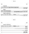
- a COM command with a header with five bytes whether or not followed by a data field
- a RES response starting-possibly with a field of data followed by two status bytes SW1 and SW2
- a WAIT wait comprising a single byte '60'.
- the bytes indicated between two accents or between square brackets are expressed in code hexadecimal.
- the first CLA byte designates an instruction class contained in the next byte
- the INS byte is a instruction code linked to a system command operating the second microcontroller CD
- P1, P2 and P3 are parameters relating to instruction.
- the first two parameters P1 and P2 are at '00'.
- Parameter P3 indicates the length lg expressed in bytes of the command data field COM when it exists. However, the setting P3 can indicate the length of data requested by a response of type [91, lg1] for data to forward in a next type response [90, 00].
- FIG. 3A relates to a pair of command-response without the CD microcontroller retransmits data.
- FIG. 3B relates to data transmission from the CG microcontroller to the CD microcontroller with data transmission from length lg1 by the CD microcontroller.
- Figure 3C relates to sending data of length lg by the microcontroller CD to the microcontroller CG at the following an empty DATA ENVELOPE command with the zero length '00'.
- the CLA class byte is always equal to 'A0'
- the instruction byte INS has three values.
- the value '14' of the INS byte indicates a TERMINAL RESPONSE type instruction for transmit the response from the CG microcontroller to the other CD microcontroller following a command proactive contained in a RES response of type "DECT command”.
- the value '12' of the INS byte denotes a FETCH instruction which, following a type response [91, lg], prompt second CD microcontroller to transfer RES response with a data field containing an order, by example relating to a ringing call or the display of a DECT menu.
- the 'C2' value of the byte INS means an ENVELOPE instruction to transfer data from the first CG microcontroller to the second CD microcontroller when parameter P3 is equal to the length lg of the data field of the ENVELOPE command as shown in Figure 3B, or to allow the second CD microcontroller send a proactive order request with the answer [91, lg] in connection with setting logic "1" of an INT interrupt wire in the LC bond, as will be seen later, when parameter P3 is equal to '00' as shown in the Figure 3C.
- the ENVELOPE statement with a data field having a length other than 0 allows the CG microcontroller to send to CD microcontroller for example a "DECT command", a "command from call control "or a” test command ".
- the TERMINAL RESPONSE instruction responds to a response containing a DECT command. Any DECT command included in a RES response established by CD microcontroller results from the exchange shown in the Figure 4 successively including a command ENVELOPE of length lg or 0, a response [91, lg1], a FETCH command [lg1], a command response Proactive DECT [90, 00], a TERMINAL command RESPONSE [lg2] and an acknowledgment response [9x, xx].
- a COM command such as ENVELOPE, FETCH, or TERMINAL RESPONSE
- the Figure 5 illustrates an example of three units successive WAIT pending response [SW1, SW2] to a TERMINAL RESPONSE command.
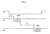
- the second microcontroller selection wire CS (Chip Select) in the LC link between microcontrollers has a first low logic state "0" maintained by the microcontroller CG dedicated to DECT communications during each transmission / reception sequence between the two microcontrollers CG and CD, that is to say during the exchange of a COM command and a RES response as shown in FIG. 6.
- the wire CS is maintained in the second high logic state "1" by the microcontroller CG so that any exchange between the CG and CD microcontrollers is prohibited and the CD microcontroller is in standby state with reduced power consumption, the CG microcontroller can then communicate with the man-machine interface with regard to data excluding DECT mode.
- the microcontroller CG After receiving the RES response, the microcontroller CG sets the CS wire to "1" if no other COM command is transmitted afterwards of the RES response so as to "sleep" the CD microcontroller and thus reduce consumption of energy from it.
- the transition from state “0" to state “1" of the CS wire normally after a response RES, or by mistake during the exchange of a COM command and RES response causes termination immediate order / response sequence and delivery to zero of the data in reception and transmission in the CD microcontroller.
- the CG microcontroller When the CG microcontroller does not receive response at the end of T2 (time-out), or when the CG microcontroller does not understand the RES response sent to him, he stops immediately exchange passing the CS wire of state "0" to state "1", then toggles the state of the wire CS at "0" and re-issues the COM command on the TX wire after a T1 guard time. This re-broadcast may be launched up to three trials. If these three attempts fail, the CG microcontroller abandons the exchange. If it is an ENVELOPE or TERMINAL instruction RESPONSE, the CG microcontroller indicates to the user on the AF display "BD block absent". This principle applies to ENVELOPE instructions of length no null and FETCH instructions, but not ENVELOPE instructions of zero length.
- CG microcontroller numbers COM commands made up of an ENVELOPE of non-zero length. Two successive orders have numbers so that the CG microcontroller differentiates a new command of a repeated command. Through therefore, when the CD microcontroller receives two successive orders containing the same number, it does not ignore the second command and respond with a RES response.
- the second CD microcontroller makes a first logical change of state of the wire INT interrupt, when the CD microcontroller wakes up and intends to send data or a proactive command to the CG microcontroller or to interrogate it.
- the CD microcontroller performs a first change of the high logic state "1" in the low logic state "0" of the INT wire.
- the CD microcontroller performs a second state change of the INT wire from state "0" to state "1".
- the CD microcontroller can relaunch this request three consecutive times. If the third ENVELOPE command request length null fails, CD microcontroller resets according to a first variant, or abandons the request of order in progress according to a second variant, or continues the order request attempts according to a third variant.
- the CD microcontroller positions the INT wire in the state "0". For example, as shown in Figure 8, the CD microcontroller order request intervenes during the choice in a menu relating to DECT mode, after a FETCH command, a response invitation to use the CL keyboard [GET INKEY, 90, 00], pressing a key on the CL keyboard and waiting by the CD microcontroller until the user has choose the menu.
- the microcontroller CD sets to "0" the INT wire which causes the session to be abandoned (menu in progress) by the CG microcontroller which returns to the rest.
- the microcontroller CG transmits the TERMINAL command RESPONSE to the microcontroller CD with the result "session abandoned”.
- the CD microcontroller then puts at "1" the interrupt wire INT and sends a response [91, lg] to start another session specific to the establishment of the incoming call.
- This session begins with a FETCH command transmitted by the CG microcontroller and then a incoming call establishment response [SETUP, 90, 00] so as to trigger the BU buzzer with a ring signal.
- the DMT terminal can work exclusively in GSM or DECT mode, in prohibiting any communication through the interface relating to the other mode of communication so avoid mutual disruption between RG and RD radio interfaces in the DMT terminal.
- the CG microcontroller no longer has need for exclusivity, following the end of a GSM communication, it ends this by a RADIO STATUS command.
- the CG microcontroller goes radio exclusive in DECT mode.
- the hold key TP line which also serves as a Redial key for redial of the last telephone number and key amplified listening is also requested for turn on the terminal, i.e. to turn on the battery included in the BD removable block, electronic circuits of terminal, such as CG and CD microcontrollers.
- the hang up key TR also serves to stop button to de-energize circuits electronic in the BG and BD blocks of the terminal when the latter is no longer in communication.
- the third wire ON in the LC link between the microcontrollers CG and CD also serves to control the stop, that is to say to turn off the power, and to start up, that is to say to be energized, from the second block BD by the microcontroller CG.
- stopping the BD block while the DMT terminal is in GSM mode reduces the power consumption of the DMT terminal.
- the CG microcontroller When the CG microcontroller wishes radio exclusivity for mode communication GSM as shown in figure 9, it sends a envelope with a stop instruction [SHUTDOWN] at CD microcontroller which establishes a response [90, 00] to following which, the CD microcontroller launches stopping all applications and radio communications in progress.
- the CD microcontroller When the CD microcontroller is ready, it sends to the microcontroller CG a stop request according to the sequence described below with reference to the figure 10, as a result of which the microcontroller CG puts in logic low state "0" the wire ON to cut the power supply mainly from the CD microcontroller by BA battery.
- an exchange according to the invention is established as shown in the figure 10, with an ENVELOPE command of zero length, a response [91, xx], a FETCH command, and a response DECT command button [OFF, 90, 00] so that the CD microcontroller asks the CG microcontroller to switch off the BD block battery voltage setting the wire ON to "0".
- This ON wire zeroing of the BD block by the CG microcontroller to cut the BD block supply can precede the transmission a TERMINAL RESPONSE command which is ignored by the CD microcontroller.
- the terminal reboots in dual mode automatic. If the DMT terminal is in another mode than DECT mode, the CG microcontroller tells the CD microcontroller after the CD microcontroller be turned on again by switching the ON wire from state "0" to state "1" by the CG microcontroller followed by a procedure exchange similar to that of Figure 9, in replacing the OFF response with an ON response such as shown in Figure 10. Then, the microcontroller CG can send a COM [SELECT] command to qualify to the CD microcontroller the radio terminal which was in radio link with the RD interface.
Abstract
Description
La présente invention concerne un dialogue entre deux contrôleurs. Un premier contrôleur est maítre et transmet des premières unités de données de protocole à un deuxième contrôleur qui est esclave du premier contrôleur et répond aux premières unités par des deuxièmes unités de données de protocole. Le deuxième contrôleur, l'esclave, ne peut transmettre des données qu'en réponse à une commande du premier contrôleur.The present invention relates to a dialogue between two controllers. A first controller is master and transmits first units of protocol data to a second controller who is a slave to the first controller and responds to the first units with second protocol data units. The second controller, the slave, cannot transmit data that in response to a command from the first controller.
Un tel dialogue est par exemple instauré entre le microcontrôleur dans une carte à puce et le microcontrôleur d'un moyen d'accueil de la carte. Par exemple, la carte à puce est une carte SIM (Subscriber Identity Module) et le moyen d'accueil est un terminal radiotéléphonique mobile. Les microcontrôleurs dans la carte SIM et le terminal dialoguent selon un protocole d'échange de données asynchrone connu sous les termes "SIM application Toolkit" qui permet à la carte de déclencher des actions dans le terminal.For example, such a dialogue is established between the microcontroller in a smart card and the microcontroller of a card reception means. Through example, the smart card is a SIM card (Subscriber Identity Module) and the means of reception is a mobile radiotelephone terminal. The microcontrollers in the SIM card and the terminal interact according to a data exchange protocol asynchronous known as "SIM application Toolkit "which allows the card to trigger actions in the terminal.
Toutefois, le microcontrôleur dans le terminal est encore le maítre du rythme des échanges. Pour que le microcontrôleur dans la carte puisse entreprendre une action, le terminal interroge périodiquement (polling en anglais) la carte SIM pro-active au moyen d'une commande STATUS afin notamment d'inviter la carte à enclencher une action.However, the microcontroller in the terminal is still the master of the rhythm of the exchanges. So that the microcontroller in the card can undertake an action, the terminal periodically interrogates (polling in English) the pro-active SIM card using a STATUS command, in particular to invite the card to trigger an action.
La vitesse de réaction du microcontrôleur dans la carte dépend alors de la périodicité d'interrogation du microcontrôleur dans le terminal et ainsi ne permet pas au microcontrôleur de la carte de lancer une action dès que celle-ci est nécessaire. The reaction speed of the microcontroller in the card then depends on the periodicity interrogation of the microcontroller in the terminal and so does not allow the card microcontroller to launch an action as soon as it is necessary.
L'objectif principal de l'invention est de fournir un procédé de dialogue entre deux contrôleurs de type maítre et esclave tels que définis ci-dessus ne présentant pas l'inconvénient précédent.The main objective of the invention is to provide a method of dialogue between two controllers master and slave type as defined above not having the above drawback.
A cette fin, un procédé de dialogue selon lequel un premier contrôleur transmet des premières unités de données auxquelles un deuxième contrôleur répond par des deuxièmes unités de données, est caractérisé par un premier changement d'état logique d'un premier fil entre les contrôleurs effectué par le deuxième contrôleur lorsque celui-ci décide d'envoyer une commande au premier contrôleur, une transmission d'une première unité de données prédéterminée par le premier contrôleur à la suite du premier changement d'état, et un deuxième changement d'état logique du premier fil opposé au premier changement et la transmission d'une deuxième unité de données effectués par le deuxième contrôleur pour répondre à la commande prédéterminée.To this end, a process of dialogue according to which a first controller transmits first units data to which a second controller responds by second data units, is characterized by a first logical state change of a first wire between the controllers made by the second controller when the latter decides to send a command to the first controller, a transmission of a first unit of data predetermined by the first controller following the first change state, and a second logical state change of the first thread opposed to the first change and the transmission of a second data unit performed by the second controller to respond to the predetermined order.
Le premier changement d'état logique du premier fil, ou de tout autre moyen de liaison entre les deux contrôleurs, est pris à l'initiative du deuxième contrôleur, le contrôleur qui était "esclave", peut ainsi réagir immédiatement, par exemple à un événement extérieur, sans attendre l'envoi périodique d'une première unité de données particulière par le premier contrôleur. L'événement extérieur peut être un appel entrant du deuxième contrôleur lorsque celui-ci est dédié à la gestion de communications téléphoniques et souhaite utiliser immédiatement des moyens périphériques gérés par le premier contrôleur.The first logical state change from the first wire, or any other connecting means between the two controllers, is taken on the initiative of the second controller, the controller who was a "slave", can thus react immediately, for example to a external event, without waiting for periodic sending of a first particular data unit by the first controller. The outdoor event can be an incoming call from the second controller when this one is dedicated to communications management and want to immediately use peripheral means managed by the first controller.
L'unité de données prédéterminée succédant au premier changement d'état logique diffère d'une commande STATUS classique et est, selon une réalisation préférée, une enveloppe contenant un champ de données vide.The predetermined data unit succeeding the first logical state change differs from classic STATUS command and is, according to a preferred embodiment, an envelope containing a empty data field.
En outre, selon l'invention, une commande pro-active peut être lancée depuis le deuxième contrôleur avant qu'une session de séquences commande-réponse soit terminée, ce qui est impossible dans une session entre une carte SIM et un terminal selon la technique antérieure. Ainsi selon l'invention, toute première unité de données transmise par le premier contrôleur entre des premier et deuxième changements d'état du premier fil est ignorée par le deuxième contrôleur lorsque celui-ci décide d'envoyer une commande au premier contrôleur alors qu'une session de dialogue est en cours entre les contrôleurs.Furthermore, according to the invention, a proactive control can be launched from the second controller before a command-response sequence session be completed, which is impossible in a session between a SIM card and a terminal according to the technique anterior. Thus according to the invention, very first data unit transmitted by the first controller between first and second state changes of first wire is ignored by the second controller when the latter decides to send an order to first controller while a dialogue session is in progress between controllers.
La présente invention poursuit également un deuxième objectif pour diminuer la consommation électrique du deuxième contrôleur qui, selon la technique antérieure, est actif même entre deux interrogations successives par le premier contrôleur.The present invention also pursues a second objective to reduce consumption the second controller which, according to the prior art, is active even between two successive interrogations by the first controller.
Pour atteindre ce deuxième objectif, l'invention prévoit un maintien d'un premier état logique d'un deuxième fil entre les contrôleurs par le premier contrôleur seulement pendant chaque échange de première et deuxième unités de données, afin que le deuxième contrôleur ainsi sélectionné par le premier contrôleur soit actif seulement pendant l'échange. Par contre, le deuxième contrôleur est en veille et donc fonctionne avec une consommation électrique réduite lorsque le deuxième fil est à un deuxième état logique entre deux échanges successifs de première et deuxième unités de données, c'est-à-dire de séquences commande-réponse. To achieve this second objective, the invention provides for maintaining a first logical state of a second wire between controllers by the first controller only during each exchange of first and second data units, so that the second controller selected by the first controller is active only during exchange. However, the second controller is on standby and so works with power consumption reduced when the second wire is at a second logical state between two successive exchanges of first and second data units, i.e. command-response sequences.
L'invention prévoit également un maintien d'un troisième fil entre les contrôleurs à un premier état logique par le premier contrôleur pour mettre hors tension le deuxième contrôleur à la suite d'une première unité de données prédéterminée établie par le premier contrôleur, et/ou en réponse à une deuxième unité de données prédéterminée établie par le deuxième contrôleur. Par exemple, le deuxième contrôleur est mis hors tension lorsque le premier contrôleur est à un premier mode de fonctionnement exclusif de toute relation avec le deuxième contrôleur. Cette caractéristique diminue encore la consommation électrique du deuxième contrôleur pendant des périodes de fonctionnement du premier contrôleur pour lesquelles le premier contrôleur n'a aucune utilité.The invention also provides for maintaining a third wire between controllers to a first state logic by the first controller to put out voltage the second controller following a first predetermined data unit established by the first controller, and / or in response to a second predetermined data unit established by the second controller. For example, the second controller is powered off when the first controller is at a first mode of operation exclusive of any relationship with the second controller. This characteristic further decreases the power consumption of the second controller during periods of operation of the first controller for which the first controller has no use.
Selon une réalisation préférée de l'invention, les premier et deuxièmes contrôleurs sont compris dans un terminal radiotéléphonique et dédiés respectivement à des premier et deuxième modes de communication afin que le premier contrôleur mette à disposition du deuxième contrôleur une interface homme-machine. L'interface homme-machine peut comprendre notamment un afficheur et un clavier utilisé quel que soit le mode de communication sélectionné, par exemple le mode GSM auquel est dédié le premier contrôleur et le mode DECT auquel est dédié le deuxième contrôleur, ou inversement.According to a preferred embodiment of the invention, the first and second controllers are included in a radiotelephone terminal and dedicated first and second modes respectively communication so that the first controller puts on layout of the second controller an interface man-machine. The human-machine interface can include a display and a keyboard used regardless of the communication mode selected, for example the GSM mode to which is dedicated the first controller and the DECT mode to which dedicated the second controller, or vice versa.
De préférence, le terminal radiotéléphonique de l'invention est aussi compact que ceux selon la technique antérieure. A cette fin, le premier contrôleur et l'interface homme-machine sont contenus dans un premier bloc, et le deuxième contrôleur et un moyen d'alimentation électrique des contrôleurs sont contenus dans un deuxième bloc emboítable dans le premier bloc.Preferably, the radiotelephone terminal of the invention is as compact as those according to the prior art. To this end, the first controller and human-machine interface are contained in a first block, and the second controller and a means of power supply the controllers are contained in a second nestable block in the first block.
D'autres caractéristiques et avantages de la présente invention apparaítront plus clairement à la lecture de la description suivante de plusieurs réalisations préférées de l'invention en référence aux dessins annexés correspondants dans lesquels :
- la figure 1 est un bloc-diagramme schématique d'un terminal radiotéléphonique bimode muni de deux microcontrôleurs mettant en oeuvre le procédé de dialogue selon l'invention, l'environnement du terminal étant également montré ;
- la figure 2 est un diagramme de première et deuxièmes unités de données de protocole échangées entre les deux microcontrôleurs ;
- les figures 3A, 3B et 3C montrent trois diagrammes principaux de dialogue entre les deux microcontrôleurs ;
- la figure 4 est un diagramme de dialogue entre les microcontrôleurs afin que le deuxième microcontrôleur transmette une commande pro-active au premier microcontrôleur ;
- la figure 5 un diagramme de dialogue entre les microcontrôleurs lorsque le premier microcontrôleur est en attente d'une réponse du deuxième microcontrôleur ;
- la figure 6 est un diagramme d'un signal de sélection de deuxième microcontrôleur en correspondance à une séquence commande-réponse entre les microcontrôleurs ;
- la figure 7 est un diagramme montrant le réveil du deuxième microcontrôleur lorsque celui-ci doit transmettre des données ou une commande pro-active au premier microcontrôleur ou interroger celui-ci ;
- la figure 8 montre l'interruption d'une session de dialogue entre les microcontrôleurs lorsque le deuxième microcontrôleur souhaite signaler un appel ; et
- les figures 9 et 10 sont des diagrammes de dialogue entre les microcontrôleurs respectivement selon deux variantes lorsque le premier microcontrôleur met hors tension le deuxième microcontrôleur.
- FIG. 1 is a schematic block diagram of a dual-mode radiotelephone terminal provided with two microcontrollers implementing the dialogue method according to the invention, the environment of the terminal also being shown;
- Figure 2 is a diagram of first and second protocol data units exchanged between the two microcontrollers;
- FIGS. 3A, 3B and 3C show three main diagrams of dialogue between the two microcontrollers;
- FIG. 4 is a dialogue diagram between the microcontrollers so that the second microcontroller transmits a proactive command to the first microcontroller;
- FIG. 5 a dialogue diagram between the microcontrollers when the first microcontroller is awaiting a response from the second microcontroller;
- FIG. 6 is a diagram of a second microcontroller selection signal in correspondence with a command-response sequence between the microcontrollers;
- FIG. 7 is a diagram showing the awakening of the second microcontroller when the latter must transmit data or a proactive command to the first microcontroller or interrogate the latter;
- FIG. 8 shows the interruption of a dialogue session between the microcontrollers when the second microcontroller wishes to signal a call; and
- Figures 9 and 10 are dialog diagrams between the microcontrollers respectively according to two variants when the first microcontroller turns off the second microcontroller.
Un terminal radiotéléphonique mobile bimode DMT (Dual Mode Terminal) est capable de communiquer en un premier mode de communication dit GSM (Global System for Mobile communication) ou dans un deuxième mode de communication dit DECT (Digital Enhanced Cordless Telecommunications). Dans la description ci-après, le premier mode GSM désigne de manière indifférente une communication avec un réseau de radiotéléphonie RR de type GSM 900 ou de type DCS 1800 (Digital Cellular System) dont le sous-réseau fixe est schématisé dans la figure 1 par une station de base BTS, un contrôleur de station de base BSC et un commutateur de service mobile MSC raccordé à un commutateur CM d'un réseau de téléphonie RT, par exemple le réseau radiotéléphonique public. Lorsque le terminal DMT communique en mode DECT, il échange des signaux à travers une borne radio BR qui est reliée à un commutateur CM d'un réseau téléphonique fixe RT tel que le réseau téléphonique public ou un réseau numérique à intégration de services RNIS à travers une ligne téléphonique d'abonné et éventuellement à travers un commutateur privé PABX. La borne BR dessert notamment d'autres terminaux téléphoniques portables fonctionnant au moins en mode DECT.A dual mode mobile terminal DMT (Dual Mode Terminal) is capable of communicating in a first mode of communication called GSM (Global System for Mobile communication) or in a second mode of communication called DECT (Digital Enhanced Cordless Telecommunications). In the description below, the first GSM mode indifferently designates a communication with a RR radiotelephone network of GSM 900 type or of DCS 1800 (Digital Cellular System) type, the fixed sub-network of which is shown diagrammatically in FIG. 1. a base station BTS, a base station controller BSC and a mobile service switch MSC connected to a switch CM of a telephony network RT, for example the public radiotelephone network. When the terminal DMT communicates in DECT mode, it exchanges signals through a radio terminal BR which is connected to a switch CM of a fixed telephone network RT such as the public telephone network or a digital network with integration of ISDN services through a subscriber telephone line and possibly through a PABX private switch. The BR terminal notably serves other portable telephone terminals operating at least in DECT mode.
Comme montré en détail à la figure 1, le terminal radiotéléphonique mobile bimode DMT comprend une première partie BG principalement dédiée à des communications selon le premier mode GSM et une deuxième partie BD dédiée à des communications selon le deuxième mode DECT. Bien que ces deux parties BG et BD puissent être contenues dans un même boítier de terminal, ces parties selon la réalisation illustrée à la figure 1 sont complètement distinctes et séparées et contenues respectivement dans un boítier appelé ci-après bloc GSM BG et un boítier appelé ci-après bloc DECT BD reliés entre eux par une triple liaison à contacts électriques LC-LA-LB. Selon cette réalisation préférée, le bloc BD dédié aux communications DECT est contenu dans le bloc de batterie BA amovible d'un terminal radiotéléphonique classique GSM dont le boítier avec le clavier constituent le bloc BG. Ainsi, outre la liaison LB relative à l'alimentation électrique du bloc BG par le bloc BD contenant la batterie BA, la liaison entre les blocs BG et BD est complétée par une liaison LC entre des microcontrôleurs et une liaison audio LA entre des interfaces audio. Les liaisons LA, LB et LC sont composées respectivement de trois fils, quatre fils et cinq fils, chaque "fil" étant en pratique constitué par deux rubans conducteurs s'étendant respectivement dans les blocs et dont les extrémités viennent en contact lorsque le bloc BD est fixé par emboítement dans la face arrière du bloc BG.As shown in detail in Figure 1, the DMT dual mode mobile radiotelephone terminal includes a first part BG mainly dedicated to communications according to the first GSM mode and a second BD section dedicated to communications according to the second DECT mode. Although these two parts BG and BD can be contained in the same box terminal, these parts according to the illustrated embodiment in Figure 1 are completely separate and separated and contained respectively in a case hereinafter called GSM BG block and a case hereinafter called DECT BD block linked together by a triple LC-LA-LB electrical contact connection. According to this preferred production, the BD block dedicated to DECT communications is contained in the block of removable BA battery of a radiotelephone terminal classic GSM including the case with the keyboard constitute the block BG. So, in addition to the LB link relating to the power supply of the BG block by the BD block containing the BA battery, the connection between blocks BG and BD is supplemented by an LC link between microcontrollers and an LA audio link between audio interfaces. LA, LB and LC connections are made up of three wires, four sons and five sons, each "thread" being in practice consisting of two conductive tapes extending respectively in the blocks and whose ends come into contact when the BD block is fixed by nesting in the rear face of the BG block.
Chaque bloc BG, BD est organisé autour d'un microcontrôleur respectif CG, CD qui comprend classiquement un microprocesseur, une mémoire ROM et une mémoire RAM et qui gère des communications selon le premier mode GSM, respectivement le deuxième mode DECT comme dans un terminal radiotéléphonique de type GSM, respectivement de type DECT.Each block BG, BD is organized around a respective microcontroller CG, CD which includes conventionally a microprocessor, a ROM memory and a RAM memory which manages communications according to the first GSM mode, respectively the second mode DECT as in a radiotelephone terminal of the type GSM, DECT type respectively.
Chaque microcontrôleur CG, CD contrôle une interface audio AG, AD comprenant principalement un circuit de codage et décodage de parole et une interface radio RG, RD comprenant principalement un modulateur et un démodulateur, des convertisseurs analogique-numérique et numérique-analogique, des circuits de transposition de fréquence et un duplexeur de voies de transmission et de réception.Each microcontroller CG, CD controls an audio interface AG, AD mainly comprising a speech coding and decoding circuit and a radio interface RG, RD mainly comprising a modulator and a demodulator, analog-digital and digital-analog converters, circuits for frequency transposition and a duplexer for transmission and reception channels.
Les interfaces audio AG et AD sont reliées par la liaison LA comprenant un fil de masse M, un fil de transmission de signal audio analogique AUT et un fil de réception audio analogique AUR. Lorsque le terminal DMT est en mode de communication DECT, le fil AUT transmet un signal audio de l'usager du terminal depuis un microphone MI de l'interface AG vers l'interface AD, et le fil AUR reçoit un signal audio d'un interlocuteur distant depuis l'interface AD vers un écouteur EC relié à l'interface AG. En communication de type GSM, l'interface audio AG gère le volume et l'annulation d'écho et ignore l'interface AD. En communication de type DECT, l'interface audio AD gère les demandes de réglage de volume suite à des appuis de touches de clavier VM et VP et l'annulation d'écho par l'intermédiaire de paires de commande-réponse entre les microcontrôleurs CG et CD, comme si l'interface audio AD était reliée directement au microphone MI et à l'écouteur EC à travers l'interface audio AG devenue transparente.The AG and AD audio interfaces are connected by the LA bond comprising a ground wire M, a analog audio signal transmission AUT and one wire AUR analog audio reception. When the DMT terminal is in DECT communication mode, the AUT wire transmits an audio signal from the user of the terminal from MI microphone from AG interface to the AD interface, and the AUR wire receives a signal audio of a remote party from the interface AD to an EC listener connected to the AG interface. In GSM type communication, the AG audio interface manages volume and echo cancellation and ignore the AD interface. In DECT communication, AD audio interface handles requests for adjustment of volume after pressing VM keyboard keys and VP and echo cancellation via command-response pairs between microcontrollers CG and CD, as if the audio interface AD is connected directly to the MI microphone and to the EC earphone at through the AG audio interface that has become transparent.
Les interfaces radio RG et RD fonctionnent sous les commandes respectives du microcontrôleur CG et CD selon les protocoles de communication GSM et DECT et sont ainsi indépendantes.The RG and RD radio interfaces operate under the respective commands of the CG and CD microcontroller according to GSM and DECT communication protocols and are thus independent.
Outre le microphone MI et l'écouteur EC, le premier bloc BG dédié aux communications selon le premier mode GSM met à la disposition du deuxième bloc BD une interface homme-machine comportant un afficheur à cristaux liquides AF, un clavier CL, un buzzer BU et une carte à puce personnelle SIM (Suscriber Identity Module). Le buzzer BU reproduit des mélodies de sonnerie notamment pour divers types d'appel. Les mélodies sont initialement choisies par l'usager et sont sélectionnées pour partie par le microcontrôleur CG pour des communications en mode GSM et pour partie par le microcontrôleur CD pour des communications en mode DECT. La carte SIM est amovible du bloc BG et contient principalement un microcontrôleur avec des algorithmes de communication et d'application spécifiques et le profil d'abonnement de l'usager propriétaire de la carte SIM. Les quatre éléments AF, CL, BU et SIM sont gérés par le microcontrôleur CG naturellement pour une communication de type GSM et indirectement depuis le microcontrôleur CD pour une communication de type DECT.In addition to the MI microphone and the EC earpiece, the first BG block dedicated to communications according to first GSM mode makes available to the second BD block a man-machine interface comprising a AF liquid crystal display, CL keyboard, BU buzzer and a personal SIM card (Suscriber Identity Module). BU buzzer reproduced ringing melodies especially for various types call. The melodies are initially chosen by the user and are selected in part by the CG microcontroller for mode communications GSM and partly by the CD microcontroller for communications in DECT mode. The SIM card is removable from the BG block and mainly contains a microcontroller with communication algorithms and specific application and profile of subscription of the user owner of the card SIM. The four elements AF, CL, BU and SIM are managed by the CG microcontroller naturally for a GSM type communication and indirectly from CD microcontroller for type communication DECT.
L'afficheur AF est relié au microcontrôleurs CG et CD à travers deux fils TX et RX pour échanger des commandes et réponses entre les microcontrôleurs, comme on le verra dans la suite. En particulier, le microcontrôleur CD gère des menus pour communication DECT visualisés sur l'afficheur AF avec des caractères acceptés par les commandes échangées entre la carte SIM et le microcontrôleur CG connues sous l'appellation SIM Application Toolkit. Les caractéristiques de l'afficheur AF sont échangées entre les microcontrôleurs CG et CD lors de l'initialisation du microcontrôleur CD par le microcontrôleur CG, à la mise sous tension du terminal DMT. Le microcontrôleur CD ne gère pas directement l'affichage graphique et tient compte des caractéristiques de l'afficheur AF pour centrer des messages sur l'écran de l'afficheur. Le microcontrôleur CD signale à la borne BR (base DECT) les caractéristiques de l'afficheur conformément au protocole de communication DECT. Le microcontrôleur CG relatif au mode de communication GSM gère les curseurs et les icônes ainsi que tout événement qui pourrait interrompre un affichage. Lorsque le terminal DMT est sous couverture d'une borne radio BR, le mode DECT ayant été sélectionné automatiquement ou manuellement, le microcontrôleur CD visualise sur l'afficheur AF à travers le microcontrôleur CG un identifiant, tel que nom, de la borne radio BR qu'a attribué l'usager du terminal DMT lorsque celui-ci s'est déclaré auprès de la borne BR selon une procédure connue pour le mode DECT. L'identifiant de la borne BR ainsi que l'identifiant, tel que nom, de l'opérateur du réseau de radiotéléphonie RR pour le mode GSM sont affichés au début d'un menu principal notamment après mise sous tension du terminal par sollicitation d'une touche de mise sous tension et composition d'un code confidentiel au clavier CL, ou après réveil du terminal, ou après retour au menu principal.The AF display is connected to the CG and CD microcontrollers through two wires TX and RX to exchange commands and responses between the microcontrollers, as will be seen below. In particular, the CD microcontroller manages menus for DECT communication displayed on the AF display with characters accepted by the commands exchanged between the SIM card and the CG microcontroller known as the SIM Application Toolkit. The characteristics of the AF display are exchanged between the microcontrollers CG and CD during the initialization of the microcontroller CD by the microcontroller CG, when the DMT terminal is powered up. The microcontroller CD does not directly manage the graphic display and takes into account the characteristics of the AF display to center messages on the display screen. The microcontroller CD signals to the BR terminal (DECT base) the characteristics of the display in accordance with the DECT communication protocol. The microcontroller CG relating to the GSM communication mode manages the cursors and the icons as well as any event which could interrupt a display. When the DMT terminal is covered by a BR radio terminal, the DECT mode having been selected automatically or manually, the microcontroller CD displays on the AF display through the microcontroller CG an identifier, such as name, of the radio terminal BR that the user of the DMT terminal assigned when the latter declared himself to the BR terminal according to a procedure known for DECT mode. The identifier of the BR terminal as well as the identifier, such as the name, of the operator of the RR radiotelephony network for GSM mode are displayed at the start of a main menu, in particular after switching on the terminal by requesting a power-on key and dialing a confidential code on the CL keyboard, or after waking up the terminal, or after returning to the main menu.
Outre l'afficheur AF sur la face avant du bloc BG du terminal DNT, celle-ci présente le clavier de numérotation classique à douze touches CL et plusieurs touches supplémentaires précisées ci-après, selon une réalisation connue d'un terminal radiotéléphonique mobile GSM. Les touches supplémentaires sont une touche de raccroché TR, par exemple rouge ; une touche de prise de ligne TP, par exemple verte ; une "touche centrale de navigation" comportant à gauche et à droite une touche d'effacement C (Clear), une touche de validation OK et des touches d'ascenseur avec flèche vers le haut FH et flèche vers'le bas FB ; et deux touches de réglage du volume sonore de l'écouteur, une touche de diminution de volume VM et une touche d'augmentation de volume VP disposées dessous l'écran de l'afficheur AF et respectivement sensiblement au-dessus des touches TR et TP.In addition to the AF display on the front face of the block BG of the terminal DNT, this presents the conventional dialing keyboard with twelve keys CL and several additional keys specified below, according to a known embodiment of a GSM mobile radiotelephone terminal. The additional keys are an on-hook key TR, for example red; a line hold key TP, for example green; a "central navigation key" comprising on the left and right an erasing key C (Clear), an OK validation key and elevator keys with up arrow FH and down arrow FB; and two buttons for adjusting the sound volume of the earpiece, a button for decreasing the volume VM and a button for increasing the volume VP located below the screen of the AF display and respectively substantially above the buttons TR and TP .
Le clavier CL et les touches supplémentaires sont utilisés de la même manière pour une communication en mode GSM comme dans un terminal GSM classique, et pour une communication en mode DECT comme dans un terminal classique DECT. Par exemple, pour un appel sortant, les touches du clavier CL servent à composer le numéro d'appel supposé à au plus N=1 chiffre pour un demandé ayant un terminal desservi par la borne radio BR et supposé comprendre au moins N+1 chiffres pour un demandé équipé d'un terminal téléphonique fixe ou d'un terminal radiotéléphonique mobile ayant généralement au moins dix chiffres, y compris pour une communication internationale. Toutefois, quel que soit le mode de communication, l'usager compose le numéro téléphonique du demandé avant d'appuyer sur la touche de prise de ligne TP, conformément à l'établissement d'un appel sortant en mode GSM, et à l'inverse d'un appel sortant en mode DECT. Ainsi, indépendamment du mode de communication sélectionné, la touche TP déclenche l'établissement d'une communication radio avec la station de base BTS auquel est rattaché le terminal DMT momentanément lorsque celui-ci fonctionne en mode GSM, ou une communication radio avec la borne BR dans-la couverture de laquelle le terminal DMT se trouve momentanément.CL keyboard and additional keys are used in the same way for a communication in GSM mode as in a GSM terminal classic, and for communication in DECT mode as in a classic DECT terminal. For example, for an outgoing call, the keys on the keyboard CL are used to dial the supposed phone number at at plus N = 1 digit for a called party with a terminal served by the BR radio terminal and assumed to include at least N + 1 digits for a called party equipped with a landline telephone terminal or terminal mobile radiotelephone generally having at least ten digits, including for communication international. However, regardless of the mode of communication, the user dials the number telephone of the called party before pressing the key TP line socket, in accordance with the establishment an outgoing call in GSM mode, and unlike a outgoing call in DECT mode. So regardless of communication mode selected, the TP key triggers the establishment of a radio communication with the BTS base station to which the DMT terminal momentarily when this one works in GSM mode, or radio communication with the BR terminal in-the cover of which the DMT terminal is momentarily located.
Deux touches supplémentaires TG et TD qui sont programmables selon l'invention et qui sont mises à la disposition d'un usager d'un terminal DECT apparaissent en bas de l'écran de l'afficheur AF en réponse à une sollicitation de la touche flèche vers le haut FH lorsqu'une communication en mode DECT est établie par le terminal DMT. Relativement à la première touche programmable TG visualisée par un logotype en bas de l'afficheur AF au-dessus de la touche VM, des appuis successifs sur les touches FH et VM sont équivalents à un appui sur la touche "rappel enregistreur" d'un terminal classique DECT. Relativement à la touche programmable de droite TD, des appuis successifs sur les touches FH et VP sont équivalents à une touche d'intercommunication dans un terminal classique DECT. Si l'usager continue à naviguer dans les menus, les deux touches programmables TG et TD disparaissent de l'afficheur AF lorsque l'usager appuie sur une autre touche, par exemple pour consulter un menu avec les touches FH et FB.Two additional keys TG and TD which are programmable according to the invention and which are set the disposition of a user of a DECT terminal appear at the bottom of the AF display screen in response to a request from the arrow key towards the high FH when a communication in DECT mode is established by the DMT terminal. Relative to the first TG programmable key displayed by a logotype at the bottom of the AF display above the VM key, successive presses on the FH keys and VM are equivalent to pressing the key "recorder recall" from a conventional DECT terminal. Relative to the right soft key TD, successive presses on the FH and VP keys are equivalent to an intercom button in a classic DECT terminal. If the user continues to navigate the menus, the two keys programmable TG and TD disappear from the display AF when the user presses another key, for example example for consulting a menu with the FH and FB.
Le terminal DMT présente trois configurations possibles qui sont une configuration en mode DECT seulement, une configuration en mode GSM seulement, et une configuration bimode automatique. L'une de ces trois configurations est sélectionnée préalablement à toute communication dans un menu "REGLAGES/RESEAU" au moyen des touches FH, FB et OK. Si la configuration en mode DECT est sélectionnée, le terminal DMT fonctionne seulement en mode DECT et l'interface radio RG est coupée du réseau de radiotéléphonie RR et le terminal se comporte comme un terminal mobile de type DECT ; dans ce mode DECT, le terminal reçoit les appels entrants externes ou d'intercommunication en mode DECT et établit des appels sortants en mode DECT. Inversement, lorsque la configuration en mode GSM est sélectionnée, l'interface radio RD est coupée de la borne radio BR et le terminal DMT se comporte comme un terminal mobile de type GSM ; dans ce mode GSM, le terminal reçoit des appels entrants de trafic GSM ou de message court SMS et établit des appels sortants en mode GSM. En configuration bimode, le terminal DMT peut commuter automatiquement entre les modes GSM et DECT en raison d'une perte de couverture ou de service relative à l'un des deux modes de communication ; dans cette configuration bimode, le terminal DMT maintient sa localisation par rapport à la station de base BTS et la borne radio BR dans la mesure où il est sous la couverture de ceux-ci.The DMT terminal has three possible configurations which are a configuration in DECT mode only, a configuration in GSM mode only, and an automatic dual mode configuration. One of these three configurations is selected prior to any communication in a "SETTINGS / NETWORK" menu using the FH, FB and OK keys. If the configuration in DECT mode is selected, the DMT terminal operates only in DECT mode and the radio interface RG is cut off from the radiotelephony network RR and the terminal behaves like a mobile terminal of DECT type; in this DECT mode, the terminal receives external incoming or intercom calls in DECT mode and establishes outgoing calls in DECT mode. Conversely, when the configuration in GSM mode is selected, the radio interface RD is cut off from the radio terminal BR and the terminal DMT behaves like a mobile terminal of GSM type; in this GSM mode, the terminal receives incoming GSM traffic or SMS short message calls and establishes outgoing calls in GSM mode. In dual mode configuration, the DMT terminal can automatically switch between GSM and DECT modes due to a loss of coverage or service relating to one of the two communication modes; in this dual-mode configuration, the DMT terminal maintains its location with respect to the base station BTS and the radio terminal BR insofar as it is under the coverage of these.
Le terme "coupée" attribué ci-dessus à une interface radio signifie que le moyen d'émission inclus dans cette interface n'émet pas, c'est-à-dire est hors tension, pour ne pas perturber le fonctionnement dû moyen de réception dans l'interface radio associée à l'autre mode de communication ; par exemple, lorsque le premier mode de communication est sélectionné pour établir une communication avec un réseau de radiotéléphonie DCS 1800, le moyen d'émission dans l'interface radio DECT RD dont la bande de fréquence d'émission est très proche de celle de la bande de fréquence du réseau DCS 1800 est coupé au moins pendant les communications en mode GSM. En variante, afin de diminuer la consommation électrique du terminal, l'interface radio correspondant au mode non sélectionné DECT ou GSM est entièrement coupée pendant une communication selon l'autre mode.The term "cut" attributed above to a radio interface means that the transmission medium included in this interface does not emit, i.e. is off, so as not to disturb the operation of reception means in the interface radio associated with the other mode of communication; through example, when the first mode of communication is selected to establish communication with a DCS 1800 radiotelephony network, the medium in the DECT RD radio interface, the transmit frequency band is very close to the frequency band of the DCS 1800 network is cut at least during mode communications GSM. Alternatively, in order to decrease consumption electrical terminal, radio interface corresponding to the unselected DECT or GSM mode is completely cut off during a call according to the other mode.
La batterie BA du terminal DMT incluse dans le bloc amovible BD est entièrement gérée par le microcontrôleur CG.The battery BA of the terminal DMT included in the removable block BD is entirely managed by the microcontroller CG.
La liaison LB comprend d'une manière connue une paire de fils TP et TM reliés aux bornes d'une thermistance TH dans le bloc BD et une paire de fils BP et BM reliés aux bornes de la batterie BA dans le bloc BD pour alimenter les circuits dans le bloc BC. Le deuxième microcontrôleur CD ainsi que les interfaces AD et RD sont alimentés également par la batterie BA mais sous le contrôle du premier microcontrôleur CG comme expliqué plus loin.The LB link comprises in a known manner a pair of TP and TM wires connected to the terminals of a TH thermistor in the BD block and a pair of wires BP and BM connected to the BA battery terminals in the BD block to supply the circuits in the BC block. The second CD microcontroller and the AD and RD interfaces are also powered by the BA battery but under the control of the first CG microcontroller as explained below.
La liaison LC entre les microcontrôleurs CG et CD comprend un premier fil, dit fil d'interruption INT, un deuxième fil, dit fil de sélection de deuxième contrôleur CS, un fil marche-arrêt de deuxième bloc ON, et deux fils de transmission et réception d'unité de données de protocole TX et RX. Les fils TX et RX sont des liens série asynchrones ayant un débit normalisé compris entre 4800 et 38400 bauds avec des octets représentatifs de caractères comportant un bit de stop, sans bit de parité. Les fils TX et RX respectivement pour des commandes COM et des réponses RES sont multiplexés avec des fils de données de l'afficheur AF. Le premier microcontrôleur CG transmet des unités de données de protocole applicatif APDU (Application Protocol Data Unit) de commande COM au deuxième microcontrôleur CD à travers le fil de transmission TX. Le deuxième microcontrôleur CD transmet des unités de données de protocole applicatif APDU de réponse RES au microcontrôleur CG à travers le fil de réception RX.The LC link between the microcontrollers CG and CD comprises a first wire, said interrupt wire INT, a second wire, said second controller selection wire CS, a second block ON-off wire ON, and two transmission wires and TX and RX protocol data unit reception. The TX and RX wires are asynchronous serial links having a standardized bit rate between 4800 and 38400 bauds with bytes representative of characters comprising a stop bit, without parity bit. The TX and RX wires respectively for COM commands and RES responses are multiplexed with data wires from the AF display. The first microcontroller CG transmits application protocol data APDU (Application Protocol Data Unit) of COM command to the second microcontroller CD through the transmission wire TX. The second microcontroller CD transmits response response application protocol data units APDU RES to the microcontroller CG through the reception wire RX.
En variante, les deux fils de transmission de données TX et RX sont remplacés par un unique fil pour un échange d'unités de données à l'alternat (half-duplex) entre les microcontrôleurs.Alternatively, the two transmission wires of TX and RX data are replaced by a single wire for an exchange of data units in the work-study program (half-duplex) between the microcontrollers.
Les séquences de commande-réponse sont des séquences d'unités de données selon le protocole de communication de l'invention analogues à celles du protocole de communication à l'alternat asynchrone caractère par caractère ou bloc de caractères par bloc de caractères, regroupées sous le terme de SIM Application Toolkit selon la norme pour carte à puce ISO 7816-3/4, c'est-à-dire selon le protocole d'échange entre le premier microcontrôleur CG et la carte SIM. Comme la carte SIM, le deuxième microcontrôleur CD est l'esclave du premier microcontrôleur CG, maítre. Grâce aux paires de commande-réponse, le premier microcontrôleur CG met à la disposition du deuxième microcontrôleur CD les éléments AF, CL, SIM, BU, MI et EC comme si le deuxième microcontrôleur CD était relié directement à ces derniers, le premier microcontrôleur CG ignorant complètement les caractéristiques du protocole de communication selon le deuxième mode DECT.Command-response sequences are sequences of data units according to the communication of the invention analogous to that of the communication protocol for asynchronous work-study character by character or block of characters by block of characters, grouped under the term SIM Application Toolkit according to the standard for smart cards ISO 7816-3 / 4, i.e. according to the protocol between the first CG microcontroller and the SIM card. Like the SIM card, the second CD microcontroller is the slave of the first CG microcontroller, master. Thanks to the pairs of command-response, the first CG microcontroller brings the layout of the second CD microcontroller the AF, CL, SIM, BU, MI and EC elements as if the second CD microcontroller was connected directly to these, the first CG microcontroller ignoring completely the characteristics of the protocol of communication in the second DECT mode.
Comme montré à la figure 2, trois types d'unités de données de protocole applicatif APDU sont prévues selon l'invention : une commande COM avec un en-tête à cinq octets suivi ou non d'un champ de données, une réponse RES débutant -éventuellement par un champ de données suivie de deux octets d'état SW1 et SW2, et une attente WAIT comprenant un seul octet '60'. Dans ce qui suit, les octets indiqués entre deux accents ou entre des crochets sont exprimés en code hexadécimal. As shown in Figure 2, three types of units APDU application protocol data are planned according to the invention: a COM command with a header with five bytes whether or not followed by a data field, a RES response starting-possibly with a field of data followed by two status bytes SW1 and SW2, and a WAIT wait comprising a single byte '60'. In the following, the bytes indicated between two accents or between square brackets are expressed in code hexadecimal.
Dans l'en-tête d'une commande COM, le premier octet CLA désigne une classe de l'instruction contenue dans l'octet suivant, l'octet INS est un code d'instruction lié à une commande du système d'exploitation du deuxième microcontrôleur CD, et P1, P2 et P3 sont des paramètres relatifs à l'instruction. Les deux premiers paramètres P1 et P2 sont à '00'. Le paramètre P3 indique la longueur lg exprimée en octets du champ de données de la commande COM lorsque celui-ci existe. Toutefois, le paramètre P3 peut indiquer la longueur des données demandée par une réponse de type [91, lg1] pour des données à transmettre dans une prochaine réponse de type [90, 00].In the header of a COM command, the first CLA byte designates an instruction class contained in the next byte, the INS byte is a instruction code linked to a system command operating the second microcontroller CD, and P1, P2 and P3 are parameters relating to instruction. The first two parameters P1 and P2 are at '00'. Parameter P3 indicates the length lg expressed in bytes of the command data field COM when it exists. However, the setting P3 can indicate the length of data requested by a response of type [91, lg1] for data to forward in a next type response [90, 00].
Les figures 3A, 3B et 3C montrent les trois cas d'échanges possibles entre les microcontrôleurs CG et CD. La figure 3A est relative à une paire de commande-réponse sans que le microcontrôleur CD retransmette des données. La figure 3B est relative à la transmission de données du microcontrôleur CG vers le microcontrôleur CD avec transmission de données de longueur lg1 par le microcontrôleur CD. La figure 3C est relative à un envoi de données de longueur lg par le microcontrôleur CD vers le microcontrôleur CG à la suite d'une commande ENVELOPE vide de données avec la longueur nulle '00' .Figures 3A, 3B and 3C show the three cases possible exchanges between CG microcontrollers and CD. FIG. 3A relates to a pair of command-response without the CD microcontroller retransmits data. FIG. 3B relates to data transmission from the CG microcontroller to the CD microcontroller with data transmission from length lg1 by the CD microcontroller. Figure 3C relates to sending data of length lg by the microcontroller CD to the microcontroller CG at the following an empty DATA ENVELOPE command with the zero length '00'.
Selon l'invention, l'octet de classe CLA est toujours égal à 'A0', et l'octet d'instruction INS a trois valeurs. La valeur '14' de l'octet INS désigne une instruction de type TERMINAL RESPONSE pour transmettre la réponse du microcontrôleur CG à l'autre microcontrôleur CD à la suite d'une commande pro-active contenue dans une réponse RES de type "commande DECT". La valeur '12' de l'octet INS désigne une instruction FETCH qui, à la suite d'une réponse de type [91, lg], invite le deuxième microcontrôleur CD à transférer une réponse RES avec un champ de données contenant une commande, par exemple relative à une sonnerie d'appel ou l'affichage d'un menu DECT. La valeur 'C2' de l'octet INS désigne une instruction ENVELOPE pour transférer des données du premier microcontrôleur CG vers le deuxième microcontrôleur CD lorsque le paramètre P3 est égal à la longueur lg du champ de données de la commande ENVELOPE comme montré à la figure 3B, ou pour permettre au deuxième microcontrôleur CD d'envoyer une demande de commande pro-active avec la réponse [91, lg] en liaison avec la mise à l'état logique "1" d'un fil d'interruption INT dans la liaison LC, comme on le verra par la suite, lorsque le paramètre P3 est égal à '00' comme montré à la figure 3C.According to the invention, the CLA class byte is always equal to 'A0', and the instruction byte INS has three values. The value '14' of the INS byte indicates a TERMINAL RESPONSE type instruction for transmit the response from the CG microcontroller to the other CD microcontroller following a command proactive contained in a RES response of type "DECT command". The value '12' of the INS byte denotes a FETCH instruction which, following a type response [91, lg], prompt second CD microcontroller to transfer RES response with a data field containing an order, by example relating to a ringing call or the display of a DECT menu. The 'C2' value of the byte INS means an ENVELOPE instruction to transfer data from the first CG microcontroller to the second CD microcontroller when parameter P3 is equal to the length lg of the data field of the ENVELOPE command as shown in Figure 3B, or to allow the second CD microcontroller send a proactive order request with the answer [91, lg] in connection with setting logic "1" of an INT interrupt wire in the LC bond, as will be seen later, when parameter P3 is equal to '00' as shown in the Figure 3C.
L'instruction ENVELOPE avec un champ de données ayant une longueur différente de 0 permet au microcontrôleur CG d'envoyer au microcontrôleur CD par exemple une "commande DECT", une "commande de contrôle d'appel" ou une "commande de test". L'instruction TERMINAL RESPONSE répond à une réponse contenant une commande DECT. Toute commande DECT incluse dans une réponse RES établie par le microcontrôleur CD résulte de l'échange montré à la figure 4 comprenant successivement une commande ENVELOPE de longueur lg ou 0, une réponse [91, lg1], une commande FETCH [lg1], une réponse de commande DECT pro-active [90, 00], une commande TERMINAL RESPONSE [lg2] et une réponse d'acquittement [9x, xx].The ENVELOPE statement with a data field having a length other than 0 allows the CG microcontroller to send to CD microcontroller for example a "DECT command", a "command from call control "or a" test command ". The TERMINAL RESPONSE instruction responds to a response containing a DECT command. Any DECT command included in a RES response established by CD microcontroller results from the exchange shown in the Figure 4 successively including a command ENVELOPE of length lg or 0, a response [91, lg1], a FETCH command [lg1], a command response Proactive DECT [90, 00], a TERMINAL command RESPONSE [lg2] and an acknowledgment response [9x, xx].
A la suite d'une commande COM, telle que ENVELOPE, FETCH, ou TERMINAL RESPONSE, le microcontrôleur CD dédié au mode de communication DECT a parfois besoin de beaucoup plus de temps qu'une durée d'attente maximale prédéterminée T2 = 35 ms pour répondre à la commande. Par exemple, dans un enchaínement de menus, le microcontrôleur CD consulte la borne radio BR par échange radio pour construire des menus. Pendant la durée des échanges entre la borne radio BR et le microcontrôleur CD, des unités de données de protocole applicatif WAIT sont transmises périodiquement toutes les T2 = 35 ms par le microcontrôleur CD afin de faire patienter le microcontrôleur CG. Dès réception d'une unité WAIT, le microcontrôleur CG redémarre un temporisateur de T3 = 40 ms. La réponse WAIT peut être utilisée par le microcontrôleur CD pendant au plus T4 = 300 ms. La figure 5 illustre un exemple de trois unités successives WAIT dans l'attente d'une réponse [SW1, SW2] à une commande TERMINAL RESPONSE.Following a COM command, such as ENVELOPE, FETCH, or TERMINAL RESPONSE, on CD microcontroller dedicated to the communication mode DECT sometimes needs a lot more time that a predetermined maximum waiting time T2 = 35 ms to respond to the command. For example, in a chaining of menus, the microcontroller CD consults the radio terminal BR by radio exchange to build menus. During the duration of the exchanges between the BR radio terminal and CD microcontroller, units of WAIT application protocol data are transmitted periodically every T2 = 35 ms by the CD microcontroller to make the patient wait CG microcontroller. Upon receipt of a WAIT unit, the microcontroller CG restarts a timer of T3 = 40 ms. The WAIT response can be used by the CD microcontroller for at most T4 = 300 ms. The Figure 5 illustrates an example of three units successive WAIT pending response [SW1, SW2] to a TERMINAL RESPONSE command.
Le fil de sélection de deuxième microcontrôleur CS (Chip Select) dans la liaison LC entre microcontrôleurs a un premier état logique bas "0" maintenu par le microcontrôleur CG dédié aux communications DECT pendant chaque séquence d'émission/réception entre les deux microcontrôleurs CG et CD, c'est-à-dire pendant l'échange d'une commande COM et d'une réponse RES comme montré à la figure 6. Le fil CS est maintenu au deuxième état logique haut "1" par le microcontrôleur CG afin que tout échange entre les microcontrôleurs CG et CD soit interdit et le microcontrôleur CD soit en état de veille avec une consommation électrique réduite, le microcontrôleur CG pouvant alors dialoguer avec l'interface homme-machine relativement à des données excluant le mode DECT. The second microcontroller selection wire CS (Chip Select) in the LC link between microcontrollers has a first low logic state "0" maintained by the microcontroller CG dedicated to DECT communications during each transmission / reception sequence between the two microcontrollers CG and CD, that is to say during the exchange of a COM command and a RES response as shown in FIG. 6. The wire CS is maintained in the second high logic state "1" by the microcontroller CG so that any exchange between the CG and CD microcontrollers is prohibited and the CD microcontroller is in standby state with reduced power consumption, the CG microcontroller can then communicate with the man-machine interface with regard to data excluding DECT mode.
Avant la transmission d'une commande COM, le premier microcontrôleur CG positionne le deuxième fil CS à l'état "0" pendant un temps de garde T1 = 5 ms pour réveiller le microcontrôleur CD. Après l'émission de la commande COM à travers le fil TX, le microcontrôleur CG maintient l'état logique "0" du fil CS au maximum pendant une durée d'attente T2 = 35 ms qui succède à la transmission de la commande COM et avant l'expiration de laquelle le microcontrôleur CD doit émettre une réponse RES à travers le fil RX. Comme déjà dit, lorsque le microcontrôleur CD a besoin d'un temps de réponse supérieur à T2, il émet au moins une réponse WAIT à l'expiration de la durée T2, puis périodiquement toutes les T2 = 35 ms.Before transmitting a COM command, the first CG microcontroller positions the second wire CS in state "0" during a guard time T1 = 5 ms to wake up the CD microcontroller. After the transmission of the COM command through the TX wire, the microcontroller CG maintains logic state "0" of the CS wire maximum during a waiting period T2 = 35 ms following the transmission of the COM command and before the expiration of which the microcontroller CD must issue a RES response through the RX wire. As already said, when the CD microcontroller has need a response time greater than T2, it emits at least one WAIT response at the end of the duration T2, then periodically every T2 = 35 ms.
Après réception de la réponse RES, le microcontrôleur CG met à l'état "1" le fil CS si aucune autre commande COM n'est transmise à la suite de la réponse RES de manière à mettre en "sommeil" le microcontrôleur CD et ainsi à réduire la consommation d'énergie de celui-ci. Le passage de l'état "0" à l'état "1" du fil CS normalement après une réponse RES, ou par erreur au cours de l'échange d'une commande COM et d'une réponse RES provoque l'arrêt immédiat de la séquence commande/réponse et la remise à zéro des données en réception et émission dans le microcontrôleur CD.After receiving the RES response, the microcontroller CG sets the CS wire to "1" if no other COM command is transmitted afterwards of the RES response so as to "sleep" the CD microcontroller and thus reduce consumption of energy from it. The transition from state "0" to state "1" of the CS wire normally after a response RES, or by mistake during the exchange of a COM command and RES response causes termination immediate order / response sequence and delivery to zero of the data in reception and transmission in the CD microcontroller.
Lorsque le microcontrôleur CG ne reçoit pas de réponse à l'expiration de la durée T2 (time-out), ou lorsque le microcontrôleur CG ne comprend pas la réponse RES qui lui a été envoyée, il arrête immédiatement l'échange en passant le fil CS de l'état "0" à l'état "1", puis bascule l'état du fil CS à "0" et ré-émet la commande COM sur le fil TX après un temps de garde T1. Cette ré-émission peut être lancée jusqu'à trois essais. Si ces trois essais échouent, le microcontrôleur CG abandonne l'échange. S'il s'agit d'une instruction ENVELOPE ou TERMINAL RESPONSE, le microcontrôleur CG indique à l'usager sur l'afficheur AF "bloc BD absent". Ce principe s'applique aux instructions ENVELOPE de longueur non nulle et aux instructions FETCH, mais pas aux instructions ENVELOPE de longueur nulle.When the CG microcontroller does not receive response at the end of T2 (time-out), or when the CG microcontroller does not understand the RES response sent to him, he stops immediately exchange passing the CS wire of state "0" to state "1", then toggles the state of the wire CS at "0" and re-issues the COM command on the TX wire after a T1 guard time. This re-broadcast may be launched up to three trials. If these three attempts fail, the CG microcontroller abandons the exchange. If it is an ENVELOPE or TERMINAL instruction RESPONSE, the CG microcontroller indicates to the user on the AF display "BD block absent". This principle applies to ENVELOPE instructions of length no null and FETCH instructions, but not ENVELOPE instructions of zero length.
Le microcontrôleur CG numérote les commandes COM constituées d'une ENVELOPE de longueur non nulle. Deux commandes successives portent des numéros différents pour que le microcontrôleur CG différencie une commande nouvelle d'une commande répétée. Par conséquent, lorsque le microcontrôleur CD reçoit deux commandes successives contenant le même numéro, il ne tient pas compte de la deuxième commande et il répond par une réponse RES.CG microcontroller numbers COM commands made up of an ENVELOPE of non-zero length. Two successive orders have numbers so that the CG microcontroller differentiates a new command of a repeated command. Through therefore, when the CD microcontroller receives two successive orders containing the same number, it does not ignore the second command and respond with a RES response.
Au lieu que le premier microcontrôleur CG interroge périodiquement le deuxième microcontrôleur CD, comme l'interrogation périodique (polling) de la carte SIM par le microcontrôleur CD par une commande périodique STATUS, le deuxième microcontrôleur CD effectue un premier changement d'état logique du fil d'interruption INT, lorsque le microcontrôleur CD se réveille et a l'intention d'envoyer des données ou une commande pro-active au microcontrôleur CG ou d'interroger celui-ci.Instead of the first microcontroller CG periodically interrogating the second microcontroller CD, like the periodic polling of the SIM card by the CD microcontroller by a periodic STATUS command, the second CD microcontroller makes a first logical change of state of the wire INT interrupt, when the CD microcontroller wakes up and intends to send data or a proactive command to the CG microcontroller or to interrogate it.
Les échanges suivants sont alors réalisés en référence à la figure 7. Le microcontrôleur CD effectue un premier changement de l'état logique haut "1" à l'état logique bas "0" du fil INT. Le premier microcontrôleur CG amorce alors le dialogue en mettant à "0" le fil de sélection CS, et après T1, en transmettant une enveloppe vide ENVELOPE [lg = 0]. En réponse à l'enveloppe vide, le microcontrôleur CD effectue un deuxième changement d'état du fil INT de l'état "0" à l'état "1". Le dialogue entre les microcontrôleurs CG et CD s'instaure normalement comme à la figure 3C, par l'émission d'une réponse [91, lg] par le microcontrôleur CD dans le fil RX, puis la transmission d'une commande FETCH dans le fil TX par le microcontrôleur CG, etc.The following exchanges are then carried out in reference to figure 7. The CD microcontroller performs a first change of the high logic state "1" in the low logic state "0" of the INT wire. The first microcontroller CG then initiates the dialogue by setting the selection thread CS to "0", and after T1, by transmitting an empty envelope ENVELOPE [lg = 0]. In response to the empty envelope, the CD microcontroller performs a second state change of the INT wire from state "0" to state "1". The dialogue between microcontrollers CG and CD installs normally as in Figure 3C, by issuing a response [91, lg] by the microcontroller CD in the RX wire, then the transmission of a FETCH command in the wire TX by CG microcontroller, etc.
Lorsque le microcontrôleur CG est en état de veille lors de la mise à l'état "0" du fil INT par l'autre microcontrôleur CD, le microcontrôleur CG doit répondre de préférence en moins de T5 = 30 ms.When the microcontroller CG is in the state of standby when setting the INT wire to "0" by the other CD microcontroller, the CG microcontroller should preferably respond in less than T5 = 30 ms.
Si le signal CS ne s'abaisse pas de l'état "1" à l'état "0", alors que le fil INT a été positionné à l'état "0" depuis plus de T5 = 30 s, le microcontrôleur CD remonte l'état du fil INT à "1" ; la demande de transmission de commande pro-active par le microcontrôleur CD n'ayant pas été comprise par le microcontrôleur CG, le microcontrôleur CD relance une demande.If the CS signal does not drop from state "1" to state "0", while the INT wire has been positioned at state "0" for more than T5 = 30 s, the CD microcontroller returns the state of the INT wire to "1"; the request for proactive command transmission by the CD microcontroller not having been understood by the microcontroller CG, the CD microcontroller relaunches a request.
Si le signal CS s'abaisse de l'état "1" à l'état "0" alors que le fil INT a été positionné à l'état "0", et que ce signal remonte de l'état "0" à l'état "1" sans que le microcontrôleur CD n'ait compris la commande COM, le microcontrôleur CD remonte le signal INT de l'état "0" à l'état "1" et après une temporisation T6 = 10 ms, il refait une demande de transmission de commande en abaissant à nouveau le fil INT à l'état "0". Le microcontrôleur CD peut relancer cette demande trois fois consécutives. Si la troisième demande de commande ENVELOPPE de longueur nulle échoue, le microcontrôleur CD se réinitialise selon une première variante, ou abandonne la demande de commande en cours selon une deuxième variante, ou poursuit les tentatives de demande de commande selon une troisième variante. If the CS signal drops from state "1" to state "0" while the INT wire has been positioned in the state "0", and that this signal goes up from the state "0" to the state "1" without the CD microcontroller having understood the COM command, the CD microcontroller raises the signal INT from state "0" to state "1" and after a timer T6 = 10 ms, it requests again command transmission by lowering the INT wire in state "0". The CD microcontroller can relaunch this request three consecutive times. If the third ENVELOPE command request length null fails, CD microcontroller resets according to a first variant, or abandons the request of order in progress according to a second variant, or continues the order request attempts according to a third variant.
Lorsque le deuxième microcontrôleur CD dédié aux communications DECT décide d'envoyer une nouvelle commande vers le microcontrôleur CG alors qu'une session de dialogue entre les microcontrôleurs comme celle montrée à la figure 7 est en cours, le microcontrôleur CD positionne le fil INT à l'état "0". Par exemple, comme montré à la figure 8, la demande de commande par le microcontrôleur CD intervient pendant le choix dans un menu relatif au mode DECT, après une commande FETCH, une réponse d'invitation à utiliser le clavier CL [GET INKEY, 90, 00], l'appui d'une touche au clavier CL et l'attente par le microcontrôleur CD tant que l'usager n'a pas choisi le menu. Si pendant cette période d'attente le microcontrôleur CD a reçu un appel entrant à travers la borne radio BR, le microcontrôleur CD met à "0" le fil INT ce qui entraíne l'abandon de la session (menu en cours) par le microcontrôleur CG qui revient au repos. Pour mettre fin au dialogue en' cours, le microcontrôleur CG transmet la commande TERMINAL RESPONSE au microcontrôleur CD avec le résultat "session abandonnée". Le microcontrôleur CD met alors à "1" le fil d'interruption INT et envoie une réponse [91, lg] afin de commencer une autre session spécifique à l'établissement de l'appel entrant. Cette session commence par une commande FETCH transmise par le microcontrôleur CG et ensuite une réponse d'établissement d'appel entrant [SETUP, 90, 00] de manière à déclencher le buzzer BU par un signal de sonnerie.When the second CD microcontroller dedicated to DECT communications decides to send a new command to the CG microcontroller while a dialogue session between microcontrollers like the one shown in figure 7 is in progress, the CD microcontroller positions the INT wire in the state "0". For example, as shown in Figure 8, the CD microcontroller order request intervenes during the choice in a menu relating to DECT mode, after a FETCH command, a response invitation to use the CL keyboard [GET INKEY, 90, 00], pressing a key on the CL keyboard and waiting by the CD microcontroller until the user has choose the menu. If during this waiting period the CD microcontroller received an incoming call through the radio terminal BR, the microcontroller CD sets to "0" the INT wire which causes the session to be abandoned (menu in progress) by the CG microcontroller which returns to the rest. To end the dialogue in progress, the microcontroller CG transmits the TERMINAL command RESPONSE to the microcontroller CD with the result "session abandoned". The CD microcontroller then puts at "1" the interrupt wire INT and sends a response [91, lg] to start another session specific to the establishment of the incoming call. This session begins with a FETCH command transmitted by the CG microcontroller and then a incoming call establishment response [SETUP, 90, 00] so as to trigger the BU buzzer with a ring signal.
Comme déjà dit, le terminal DMT peut fonctionner exclusivement en mode GSM ou en mode DECT, en interdisant toute communication à travers l'interface relative à l'autre mode de communication afin d'éviter toute perturbation mutuelle entre les interfaces radio RG et RD dans le terminal DMT. Lors d'une communication en mode GSM, grâce à une commande RADIO STATUS, le microcontrôleur CG réclame une exclusivité radio au microcontrôleur CD. Si un lien radio est en cours, le microcontrôleur CD a besoin de T3 = 30 ms pour signaler la libération de la liaison radio en mode DECT à la borne radio BR. Pendant toute cette phase d'exclusion, l'interface radio RD n'émet pas sur ses canaux radio. Par contre, le moyen de réception dans l'interface radio RD continue à suivre la borne BR. Lorsque le microcontrôleur CG n'a plus besoin d'une exclusivité, suite à la fin d'une communication GSM, il met fin à celle-ci par une commande RADIO STATUS.As already said, the DMT terminal can work exclusively in GSM or DECT mode, in prohibiting any communication through the interface relating to the other mode of communication so avoid mutual disruption between RG and RD radio interfaces in the DMT terminal. When a communication in GSM mode, thanks to a command RADIO STATUS, the CG microcontroller requires radio exclusive to CD microcontroller. If a link radio is in progress, the CD microcontroller needs T3 = 30 ms to signal the release of the link radio in DECT mode at the BR radio terminal. During all this exclusion phase, the radio interface RD does not transmit not on its radio channels. On the other hand, the means of reception in the radio interface RD continues to follow the BR terminal. When the CG microcontroller no longer has need for exclusivity, following the end of a GSM communication, it ends this by a RADIO STATUS command.
Réciproquement, en réponse à un message d'établissement d'appel entrant ou sortant en mode DECT de type SETUP transmis par le microcontrôleur CD, le microcontrôleur CG passe en exclusivité radio en mode DECT.Conversely, in response to a message incoming or outgoing call establishment in mode DECT type SETUP transmitted by the microcontroller CD, the CG microcontroller goes radio exclusive in DECT mode.
Sur la face avant du bloc BG, la touche de prise de ligne TP qui sert également de touche Bis pour rappel du dernier numéro téléphonique et de touche d'écoute amplifiée est également sollicitée pour mettre en marche le terminal, c'est-à-dire pour mettre sous tension de la batterie incluse dans le bloc amovible BD, les circuits électroniques du terminal, tels que les microcontrôleurs CG et CD. De même, la touche de raccroché TR sert également de touche d'arrêt pour mettre hors tension les circuits électroniques dans les blocs BG et BD du terminal lorsque celui-ci n'est plus en communication.On the front of the BG block, the hold key TP line which also serves as a Redial key for redial of the last telephone number and key amplified listening is also requested for turn on the terminal, i.e. to turn on the battery included in the BD removable block, electronic circuits of terminal, such as CG and CD microcontrollers. Of even, the hang up key TR also serves to stop button to de-energize circuits electronic in the BG and BD blocks of the terminal when the latter is no longer in communication.
De préférence, le troisième fil ON dans la liaison LC entre les microcontrôleurs CG et CD sert également à commander l'arrêt, c'est-à-dire à mettre hors tension, et à mettre en marche, c'est-à-dire à mettre sous tension, du deuxième bloc BD par le microcontrôleur CG. En particulier, l'arrêt du bloc BD pendant que le terminal DMT est en mode GSM réduit la consommation électrique du terminal DMT.Preferably, the third wire ON in the LC link between the microcontrollers CG and CD also serves to control the stop, that is to say to turn off the power, and to start up, that is to say to be energized, from the second block BD by the microcontroller CG. In particular, stopping the BD block while the DMT terminal is in GSM mode reduces the power consumption of the DMT terminal.
Lorsque le microcontrôleur CG souhaite l'exclusivité radio pour une communication en mode GSM comme montré à la figure 9, il envoie une enveloppe avec une instruction d'arrêt [SHUTDOWN] au microcontrôleur CD qui établit une réponse [90, 00] à la suite de laquelle, le microcontrôleur CD lance l'arrêt de toutes les applications et les communications radio en cours. Lorsque le microcontrôleur CD est prêt, il envoie au microcontrôleur CG une demande d'arrêt selon la séquence décrite ci-après en référence à la figure 10, à la suite de laquelle le microcontrôleur CG met à l'état logique bas "0" le fil ON pour couper l'alimentation principalement du microcontrôleur CD par la batterie BA. Lorsque le microcontrôleur CD souhaite lui-même être désalimenté par exemple à la suite d'un basculement manuel en mode GSM, un échange selon l'invention s'instaure comme montré à la figure 10, avec une commande ENVELOPE de longueur nulle, une réponse [91, xx], une commande FETCH, et une réponse de commande DECT d'arrêt [OFF, 90, 00] afin que le microcontrôleur CD demande au microcontrôleur CG de mettre hors de tension de batterie le bloc BD en mettant à "0" le fil ON. Cette mise à zéro du fil ON du bloc BD par le microcontrôleur CG pour couper l'alimentation du bloc BD peut précédera l'émission d'une commande TERMINAL RESPONSE qui est ignorée par le microcontrôleur CD. When the CG microcontroller wishes radio exclusivity for mode communication GSM as shown in figure 9, it sends a envelope with a stop instruction [SHUTDOWN] at CD microcontroller which establishes a response [90, 00] to following which, the CD microcontroller launches stopping all applications and radio communications in progress. When the CD microcontroller is ready, it sends to the microcontroller CG a stop request according to the sequence described below with reference to the figure 10, as a result of which the microcontroller CG puts in logic low state "0" the wire ON to cut the power supply mainly from the CD microcontroller by BA battery. When the CD microcontroller himself wants to be malnourished for example at the following a manual switch to GSM mode, an exchange according to the invention is established as shown in the figure 10, with an ENVELOPE command of zero length, a response [91, xx], a FETCH command, and a response DECT command button [OFF, 90, 00] so that the CD microcontroller asks the CG microcontroller to switch off the BD block battery voltage setting the wire ON to "0". This ON wire zeroing of the BD block by the CG microcontroller to cut the BD block supply can precede the transmission a TERMINAL RESPONSE command which is ignored by the CD microcontroller.
A la remise sous tension de batterie du microcontrôleur CD, le terminal redémarre en bimode automatique. Si le terminal DMT est dans un autre mode que le mode DECT, le microcontrôleur CG l'indique au microcontrôleur CD après que le microcontrôleur CD soit de nouveau mis sous tension par passage du fil ON de l'état "0" à l'état "1" par le microcontrôleur CG suivi par une procédure d'échange analogue à celui de la figure 9, en remplaçant la réponse OFF par une réponse ON comme montré à la figure 10. Puis, le microcontrôleur CG peut envoyer une commande COM [SELECT] pour qualifier au microcontrôleur CD la borne radio qui était en liaison radio avec l'interface RD.When the battery is switched on again CD microcontroller, the terminal reboots in dual mode automatic. If the DMT terminal is in another mode than DECT mode, the CG microcontroller tells the CD microcontroller after the CD microcontroller be turned on again by switching the ON wire from state "0" to state "1" by the CG microcontroller followed by a procedure exchange similar to that of Figure 9, in replacing the OFF response with an ON response such as shown in Figure 10. Then, the microcontroller CG can send a COM [SELECT] command to qualify to the CD microcontroller the radio terminal which was in radio link with the RD interface.
Claims (11)
Applications Claiming Priority (2)
| Application Number | Priority Date | Filing Date | Title |
|---|---|---|---|
| FR9915232A FR2802050B1 (en) | 1999-12-01 | 1999-12-01 | DIALOGUE BETWEEN TWO CONTROLLERS, PARTICULARLY IN A BIMODE DECT / GSM RADIOTELEPHONE TERMINAL |
| FR9915232 | 1999-12-01 |
Publications (3)
| Publication Number | Publication Date |
|---|---|
| EP1107625A1 true EP1107625A1 (en) | 2001-06-13 |
| EP1107625B1 EP1107625B1 (en) | 2005-04-06 |
| EP1107625B8 EP1107625B8 (en) | 2005-06-01 |
Family
ID=9552830
Family Applications (1)
| Application Number | Title | Priority Date | Filing Date |
|---|---|---|---|
| EP20000403072 Expired - Lifetime EP1107625B8 (en) | 1999-12-01 | 2000-11-06 | Dialogue between two controllers, particularly in a dual mode DECT/GSM radiotelephone terminal |
Country Status (4)
| Country | Link |
|---|---|
| EP (1) | EP1107625B8 (en) |
| DE (1) | DE60019242T2 (en) |
| ES (1) | ES2235803T3 (en) |
| FR (1) | FR2802050B1 (en) |
Cited By (1)
| Publication number | Priority date | Publication date | Assignee | Title |
|---|---|---|---|---|
| WO2007059722A1 (en) * | 2005-11-28 | 2007-05-31 | Winrich Hoseit | Dect telephone and system for dect telephony |
Families Citing this family (1)
| Publication number | Priority date | Publication date | Assignee | Title |
|---|---|---|---|---|
| DE102017007792A1 (en) * | 2017-08-18 | 2019-02-21 | Ulrich Berger | Arrangement with a mobile device and a connection device |
Citations (5)
| Publication number | Priority date | Publication date | Assignee | Title |
|---|---|---|---|---|
| DE4118993A1 (en) * | 1991-06-08 | 1992-12-10 | Aeg Mobile Communication | Mobile subscriber telephone system - has user data card allowing access to different networks using two stored subscriber numbers and separate processors |
| WO1998009462A1 (en) * | 1996-08-30 | 1998-03-05 | Ericsson Inc. | Multi-mode mobile station supporting multiple cellular telephone system operation with limited subscriber identity module card |
| WO1998027766A2 (en) * | 1996-12-19 | 1998-06-25 | Siemens Aktiengesellschaft | Method and device for reducing electricity consumption in mobile multimode telecommunication terminals |
| EP0858237A2 (en) * | 1997-02-05 | 1998-08-12 | Nokia Mobile Phones Ltd. | Intelligent network searching for a multi mode phone |
| DE19914254A1 (en) * | 1999-03-29 | 1999-07-29 | Kunze Ingeburg | Telephone call connection method for dual-mode mobile radio telephone |
-
1999
- 1999-12-01 FR FR9915232A patent/FR2802050B1/en not_active Expired - Lifetime
-
2000
- 2000-11-06 DE DE2000619242 patent/DE60019242T2/en not_active Expired - Lifetime
- 2000-11-06 EP EP20000403072 patent/EP1107625B8/en not_active Expired - Lifetime
- 2000-11-06 ES ES00403072T patent/ES2235803T3/en not_active Expired - Lifetime
Patent Citations (5)
| Publication number | Priority date | Publication date | Assignee | Title |
|---|---|---|---|---|
| DE4118993A1 (en) * | 1991-06-08 | 1992-12-10 | Aeg Mobile Communication | Mobile subscriber telephone system - has user data card allowing access to different networks using two stored subscriber numbers and separate processors |
| WO1998009462A1 (en) * | 1996-08-30 | 1998-03-05 | Ericsson Inc. | Multi-mode mobile station supporting multiple cellular telephone system operation with limited subscriber identity module card |
| WO1998027766A2 (en) * | 1996-12-19 | 1998-06-25 | Siemens Aktiengesellschaft | Method and device for reducing electricity consumption in mobile multimode telecommunication terminals |
| EP0858237A2 (en) * | 1997-02-05 | 1998-08-12 | Nokia Mobile Phones Ltd. | Intelligent network searching for a multi mode phone |
| DE19914254A1 (en) * | 1999-03-29 | 1999-07-29 | Kunze Ingeburg | Telephone call connection method for dual-mode mobile radio telephone |
Cited By (1)
| Publication number | Priority date | Publication date | Assignee | Title |
|---|---|---|---|---|
| WO2007059722A1 (en) * | 2005-11-28 | 2007-05-31 | Winrich Hoseit | Dect telephone and system for dect telephony |
Also Published As
| Publication number | Publication date |
|---|---|
| DE60019242D1 (en) | 2005-05-12 |
| EP1107625B1 (en) | 2005-04-06 |
| FR2802050A1 (en) | 2001-06-08 |
| ES2235803T3 (en) | 2005-07-16 |
| EP1107625B8 (en) | 2005-06-01 |
| DE60019242T2 (en) | 2006-01-19 |
| FR2802050B1 (en) | 2002-01-11 |
Similar Documents
| Publication | Publication Date | Title |
|---|---|---|
| EP0899973B1 (en) | Telephone with subscriber identity card | |
| US6424830B1 (en) | Portable data collection network with telephone and voice mail capability | |
| EP0766438B1 (en) | Cordless telephone system with a remote controlled peripheral device | |
| CA2158896A1 (en) | Power saving in a system including a portable radiotelephone connected to a peripheral device | |
| US20030092453A1 (en) | Methods and apparatus for communicating information from a remote wireless device to a cordless telephone system | |
| EP1107625B1 (en) | Dialogue between two controllers, particularly in a dual mode DECT/GSM radiotelephone terminal | |
| EP1120948B1 (en) | Mobile phone to be used together with a cordless telephone for a DECT base station | |
| EP1178652A1 (en) | Method and system for automatically managing network services | |
| EP3160116B1 (en) | Method for automatically pairing a plurality of wireless terminals to a network access point | |
| EP1280324B1 (en) | Acoustical room monitoring method with cordless telephones | |
| EP1096819A1 (en) | Procedure for selecting a mode with a DECT/GSM dual mode terminal | |
| EP1280323B1 (en) | Intercom method between at least three handsets in a local radiocommunication network and handset therefor | |
| JPH04120922A (en) | Radio telephony equipment | |
| WO2002041612A2 (en) | Methods and apparatus for communicating information from a remote wireless device to a cordless telephone system | |
| EP1026909A1 (en) | Mobile phone with access to a cellular network and the Internet | |
| FR2710485A1 (en) | Computer provided with means for communicating remotely via a telephone network in a wired mode or a radio mode, and a method implemented by the computer. | |
| EP0966170A1 (en) | Method for transferring a data set to a mobile phone while a call is in progress, and terminal therefore | |
| KR20040046866A (en) | Voice message transmission method of download mode | |
| EP0913983A1 (en) | Method for establishing a communication between an Internet terminal and a telephone and telephone for carrying out the method | |
| FR2691865A1 (en) | Portable or fixed handset system for telephone subscribers - has interface module connected in parallel with fixed handset transmitting signals to second set with remote telephone switching | |
| JP2005110304A (en) | System and method for downloading software or data to terminal | |
| EP1280322A1 (en) | Method of setting up an intercom communication in a local radiocommunication network | |
| WO2004084533A1 (en) | Method for downloading a melody on a switched telephone network | |
| JPH10243455A (en) | Portable telephone set | |
| EP1168785A1 (en) | Local wireless telephone network and low-cost radio base station for such a network |
Legal Events
| Date | Code | Title | Description |
|---|---|---|---|
| PUAI | Public reference made under article 153(3) epc to a published international application that has entered the european phase |
Free format text: ORIGINAL CODE: 0009012 |
|
| AK | Designated contracting states |
Kind code of ref document: A1 Designated state(s): DE ES GB IT |
|
| AX | Request for extension of the european patent |
Free format text: AL;LT;LV;MK;RO;SI |
|
| 17P | Request for examination filed |
Effective date: 20010726 |
|
| AKX | Designation fees paid |
Free format text: DE ES GB IT |
|
| GRAP | Despatch of communication of intention to grant a patent |
Free format text: ORIGINAL CODE: EPIDOSNIGR1 |
|
| RAP1 | Party data changed (applicant data changed or rights of an application transferred) |
Owner name: SAGEM SA |
|
| GRAS | Grant fee paid |
Free format text: ORIGINAL CODE: EPIDOSNIGR3 |
|
| GRAA | (expected) grant |
Free format text: ORIGINAL CODE: 0009210 |
|
| AK | Designated contracting states |
Kind code of ref document: B1 Designated state(s): DE ES GB IT |
|
| REG | Reference to a national code |
Ref country code: GB Ref legal event code: FG4D Free format text: NOT ENGLISH |
|
| RAP2 | Party data changed (patent owner data changed or rights of a patent transferred) |
Owner name: SAGEM SA |
|
| REF | Corresponds to: |
Ref document number: 60019242 Country of ref document: DE Date of ref document: 20050512 Kind code of ref document: P |
|
| REG | Reference to a national code |
Ref country code: ES Ref legal event code: FG2A Ref document number: 2235803 Country of ref document: ES Kind code of ref document: T3 |
|
| GBT | Gb: translation of ep patent filed (gb section 77(6)(a)/1977) |
Effective date: 20050824 |
|
| PLBE | No opposition filed within time limit |
Free format text: ORIGINAL CODE: 0009261 |
|
| STAA | Information on the status of an ep patent application or granted ep patent |
Free format text: STATUS: NO OPPOSITION FILED WITHIN TIME LIMIT |
|
| 26N | No opposition filed |
Effective date: 20060110 |
|
| REG | Reference to a national code |
Ref country code: GB Ref legal event code: 732E |
|
| REG | Reference to a national code |
Ref country code: GB Ref legal event code: 732E Free format text: REGISTERED BETWEEN 20090326 AND 20090401 |
|
| REG | Reference to a national code |
Ref country code: DE Ref legal event code: R082 Ref document number: 60019242 Country of ref document: DE Representative=s name: KOHLER SCHMID MOEBUS, DE |
|
| REG | Reference to a national code |
Ref country code: DE Ref legal event code: R082 Ref document number: 60019242 Country of ref document: DE Representative=s name: KOHLER SCHMID MOEBUS, DE Effective date: 20120507 Ref country code: DE Ref legal event code: R081 Ref document number: 60019242 Country of ref document: DE Owner name: SAGEMCOM SAS, FR Free format text: FORMER OWNER: SAGEM COMMUNICATION, PARIS, FR Effective date: 20120507 Ref country code: DE Ref legal event code: R082 Ref document number: 60019242 Country of ref document: DE Representative=s name: KOHLER SCHMID MOEBUS PATENTANWAELTE PARTNERSCH, DE Effective date: 20120507 |
|
| REG | Reference to a national code |
Ref country code: DE Ref legal event code: R082 Ref document number: 60019242 Country of ref document: DE Representative=s name: KOHLER SCHMID MOEBUS, DE |
|
| REG | Reference to a national code |
Ref country code: DE Ref legal event code: R081 Ref document number: 60019242 Country of ref document: DE Owner name: SAGEMCOM SAS, FR Free format text: FORMER OWNER: SAGEM TELECOMMUNICATIONS S. A., PARIS, FR Effective date: 20130129 Ref country code: DE Ref legal event code: R082 Ref document number: 60019242 Country of ref document: DE Representative=s name: KOHLER SCHMID MOEBUS, DE Effective date: 20130129 Ref country code: DE Ref legal event code: R082 Ref document number: 60019242 Country of ref document: DE Representative=s name: KOHLER SCHMID MOEBUS PATENTANWAELTE PARTNERSCH, DE Effective date: 20130129 |
|
| PGFP | Annual fee paid to national office [announced via postgrant information from national office to epo] |
Ref country code: DE Payment date: 20191021 Year of fee payment: 20 |
|
| PGFP | Annual fee paid to national office [announced via postgrant information from national office to epo] |
Ref country code: IT Payment date: 20191021 Year of fee payment: 20 Ref country code: ES Payment date: 20191202 Year of fee payment: 20 |
|
| PGFP | Annual fee paid to national office [announced via postgrant information from national office to epo] |
Ref country code: GB Payment date: 20191022 Year of fee payment: 20 |
|
| REG | Reference to a national code |
Ref country code: DE Ref legal event code: R071 Ref document number: 60019242 Country of ref document: DE |
|
| REG | Reference to a national code |
Ref country code: GB Ref legal event code: PE20 Expiry date: 20201105 |
|
| PG25 | Lapsed in a contracting state [announced via postgrant information from national office to epo] |
Ref country code: GB Free format text: LAPSE BECAUSE OF EXPIRATION OF PROTECTION Effective date: 20201105 |
|
| REG | Reference to a national code |
Ref country code: ES Ref legal event code: FD2A Effective date: 20210226 |
|
| PG25 | Lapsed in a contracting state [announced via postgrant information from national office to epo] |
Ref country code: ES Free format text: LAPSE BECAUSE OF EXPIRATION OF PROTECTION Effective date: 20201107 |