EP1107528B1 - Verfahren der Erkennung von Blöcken für einen schwindenden Kanal - Google Patents
Verfahren der Erkennung von Blöcken für einen schwindenden Kanal Download PDFInfo
- Publication number
- EP1107528B1 EP1107528B1 EP00204219A EP00204219A EP1107528B1 EP 1107528 B1 EP1107528 B1 EP 1107528B1 EP 00204219 A EP00204219 A EP 00204219A EP 00204219 A EP00204219 A EP 00204219A EP 1107528 B1 EP1107528 B1 EP 1107528B1
- Authority
- EP
- European Patent Office
- Prior art keywords
- block
- iteration
- decision
- detection
- transmission system
- Prior art date
- Legal status (The legal status is an assumption and is not a legal conclusion. Google has not performed a legal analysis and makes no representation as to the accuracy of the status listed.)
- Expired - Lifetime
Links
- 238000001514 detection method Methods 0.000 title claims description 16
- 238000000034 method Methods 0.000 title claims description 4
- 238000005562 fading Methods 0.000 title description 4
- 239000011159 matrix material Substances 0.000 claims description 21
- 230000005540 biological transmission Effects 0.000 claims description 18
- 238000001914 filtration Methods 0.000 claims description 16
- 238000004590 computer program Methods 0.000 claims 1
- 230000009466 transformation Effects 0.000 description 8
- 238000004088 simulation Methods 0.000 description 7
- 230000007423 decrease Effects 0.000 description 4
- 239000013598 vector Substances 0.000 description 4
- 230000003321 amplification Effects 0.000 description 3
- 238000003199 nucleic acid amplification method Methods 0.000 description 3
- 241000209094 Oryza Species 0.000 description 2
- 235000007164 Oryza sativa Nutrition 0.000 description 2
- 235000021183 entrée Nutrition 0.000 description 2
- 235000009566 rice Nutrition 0.000 description 2
- 230000001133 acceleration Effects 0.000 description 1
- 238000004364 calculation method Methods 0.000 description 1
- 230000000694 effects Effects 0.000 description 1
- 206010042772 syncope Diseases 0.000 description 1
Images

Classifications
-
- H—ELECTRICITY
- H04—ELECTRIC COMMUNICATION TECHNIQUE
- H04B—TRANSMISSION
- H04B15/00—Suppression or limitation of noise or interference
-
- H—ELECTRICITY
- H04—ELECTRIC COMMUNICATION TECHNIQUE
- H04L—TRANSMISSION OF DIGITAL INFORMATION, e.g. TELEGRAPHIC COMMUNICATION
- H04L25/00—Baseband systems
- H04L25/02—Details ; arrangements for supplying electrical power along data transmission lines
- H04L25/03—Shaping networks in transmitter or receiver, e.g. adaptive shaping networks
- H04L25/03006—Arrangements for removing intersymbol interference
- H04L25/03343—Arrangements at the transmitter end
-
- H—ELECTRICITY
- H04—ELECTRIC COMMUNICATION TECHNIQUE
- H04L—TRANSMISSION OF DIGITAL INFORMATION, e.g. TELEGRAPHIC COMMUNICATION
- H04L25/00—Baseband systems
- H04L25/02—Details ; arrangements for supplying electrical power along data transmission lines
- H04L25/03—Shaping networks in transmitter or receiver, e.g. adaptive shaping networks
- H04L25/03006—Arrangements for removing intersymbol interference
- H04L25/03012—Arrangements for removing intersymbol interference operating in the time domain
- H04L25/03019—Arrangements for removing intersymbol interference operating in the time domain adaptive, i.e. capable of adjustment during data reception
- H04L25/03057—Arrangements for removing intersymbol interference operating in the time domain adaptive, i.e. capable of adjustment during data reception with a recursive structure
-
- H—ELECTRICITY
- H04—ELECTRIC COMMUNICATION TECHNIQUE
- H04L—TRANSMISSION OF DIGITAL INFORMATION, e.g. TELEGRAPHIC COMMUNICATION
- H04L25/00—Baseband systems
- H04L25/02—Details ; arrangements for supplying electrical power along data transmission lines
- H04L25/03—Shaping networks in transmitter or receiver, e.g. adaptive shaping networks
- H04L25/03006—Arrangements for removing intersymbol interference
- H04L2025/03592—Adaptation methods
- H04L2025/03598—Algorithms
- H04L2025/03611—Iterative algorithms
Definitions
- the invention relates to a transmission system comprising at least one transmitter and one receiver to transmit data formatted in blocks through a transmission channel which introduces a distortion defined from multiplicative coefficients, said receiver comprising block detection means by successive iterations, said detection means including themselves means for multiplying blocks by a filtering matrix intended to compensate for said distortion.
- the invention also relates to a receiver for use in such a system, a block detection method for use in such a receiver, and a program computer for the implementation of such a method.
- the invention has important applications in the field of transmissions via a faded channel, for example a Rayleigh or Rice channel. This is the case examples of mobile radio systems and mobile satellite transmission systems.
- the object of the invention is to propose a transmission system of the above kind, having better performance.
- the values of said powers are for example chosen by applying a criterion of error minimization.
- the detector comprises means for determining the convergence of the decisions obtained during successive iterations, and means for terminating the detection when the convergence is determined. This second embodiment makes it possible on average to limit the number of iterations necessary to get closer to the performances obtained with a Gaussian channel (that is to say a channel that is not subject to fainting).
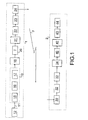
- FIG. 1 there is shown an example of a transmission system according to the invention.
- This system comprises a transmitter 1 capable of transmitting data to a receiver 2, by via a radio channel 3 subject to fading.
- the transmitter 1 comprises channel coding means 10 for coding a bit stream 11 provided by a data source 12.
- the channel coding means 10 comprise an encoder 15 which introduces redundancy on the data 12, a device for coding the data.
- assignment 16 which assigns to a group of bits a symbol chosen in a constellation, and an interleaver 17 which makes it possible to avoid the presence of error packets at the decoding level.
- the symbols delivered by the interleaver 17 are supplied to a serial / parallel converter 18 which groups the symbols in blocks X of length M. These blocks are transmitted to means 20 of orthogonal transformation.
- the output vectors Y are then transmitted to a parallel / series converter 21.
- the resulting symbol flow is interleaved by an interleaver 22 so as to ensure that the attenuation factors that will be introduced into the symbols by the channel are independent of each other. others.
- the symbols delivered by the interleaver 22 are filtered by a low-pass filter 23 and modulated by a modulator 24.
- the radio signal obtained is transmitted by the radio channel 3 which is subject to fading.
- the receiver 2 comprises demodulation means 30 for demodulating a radio signal received.
- These demodulation means 30 further comprise means for estimating and phase compensation, so that there is no phase difference between the emitted symbols and the symbols obtained at the output of the demodulation means.
- the symbols obtained at the output of the demodulation means are filtered by a low-pass filter 32 and then transmitted to a deinterleaver 33.
- the deinterleaved symbols are transmitted to a serial / parallel converter 34 which deliver blocks Z of length M. These blocks Z are transmitted to an iterative block detector 40.
- the detector 40 delivers blocks (L). These blocks (L) are transmitted to a parallel / serial converter 42.
- the stream of symbols obtained is transmitted to a deinterleaver 43, then to a decoder 44. After decoding, the decoder 44 makes final decisions on the received symbols.
- the transmission channel multiplies each transmitted symbol by a coefficient, and adds a Gaussian noise.
- the coefficients ⁇ j are independent variables. They are for example distributed according to a law of Rayleigh or Rice. When there is no phase difference between the transmitted symbols and the symbols applied to the input of the detector 40, the coefficients ⁇ j are real numbers.
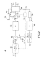
- the output of the filtering means 50 is applied to the input of a loop composed of a forward path and a return path. In its forward path the loop comprises a subtraction member 52 whose output is connected to inverse transformation means 53.
- the output of these inverse transformation means 53 is applied to a first input of a summing element 54.
- the return path includes transformation means 60 for applying the transformation defined by the orthogonal matrix T to the decision X and (i -1) which has been taken at the iteration i-1.
- Multiplication means 62 then multiply the transformed block TX and (i -1) by the product of the diagonal matrix D ⁇ and the filter matrix W (i).
- N is a Gaussian noise.
- the term is a difference between the block actually received after filtering, and the block that would have been received after the same filtering, for the decision taken at the previous iteration. This difference is called inter-symbol interference. It decreases with each iteration.
- the blocks 56 and 59 represent delay devices capable of delivering when from the iteration i the decisions X and (i-1) taken during the previous iteration.
- the elements of the filter matrix W (i) are proportional to a power p (i) of channel coefficients.
- the coefficients of the channel are real since the phase received symbols has been compensated for at the demodulation level.
- the channel coefficients are complex numbers, and the elements of the filter matrix W (i) is proportional to a power p (i) of the modulus of said coefficients.
- the powers p (i) depend on the constellation used and the signal-to-noise ratio. For example, they are chosen by simulations, assuming that the emitted symbols are known, and by applying a criterion for minimizing the bit error rate, or the variance of the difference between the input of the threshold detector. (i) and the block issued.
- the loop of the detector 40 comprises, on its return path, a convergence test member 70.
- This test member has the function of determining the convergence of the decisions obtained during the successive iterations, in order to finish detection when convergence is reached (ie inter-symbol interference is close to zero).
- p (i + 1) 1.
- the elements of the filtering matrix used in the invention are independent of the variance N o of the Gaussian noise.
- the variance No. So Gaussian noise need not be estimated here. This is an additional advantage over the cited prior art, because it decreases computational complexity, and increases the accuracy of the result.
- the transmitter comprises channel coding means 10
- the receiver comprises decoding means which use the block (L).
- the channel decoding means uses the decision X and (L) instead of the block (L).
- the channel coding means are optional, and when the transmitter does not include channel coding means, the final decision on the received symbols is taken by the threshold detector 55. In this case, it is block X and (L) which is transmitted to the parallel / serial converter 42.
- the product of the matrix diagonal D ⁇ and the filter matrix W (i) is normalized. This is an implementation choice advantageous which allows to obtain a single detector usable as well with a constellation to constant envelope with a non-constant envelope constellation. In other modes of realization could be used a non-standardized product, that is to say have a filter matrix W (i) which has a factor of proportionality with the powers of the coefficients of the channel which is different from the one used here.
- the curve obtained with the 8 th iteration is close to the result obtained with a Gaussian channel (AWGN curve) for signal-to noise higher 13,5dB.
- AWGN curve Gaussian channel
Landscapes
- Engineering & Computer Science (AREA)
- Computer Networks & Wireless Communication (AREA)
- Signal Processing (AREA)
- Power Engineering (AREA)
- Digital Transmission Methods That Use Modulated Carrier Waves (AREA)
- Detection And Prevention Of Errors In Transmission (AREA)
- Cable Transmission Systems, Equalization Of Radio And Reduction Of Echo (AREA)
- Mobile Radio Communication Systems (AREA)
Claims (10)
- Übertragungssystem mit mindestens einem Sender (1) und einem Empfänger (2) für die Übertragung in Blöcken von formatierten Daten über einen Übertragungskanal (3), der eine definierte Verzerrung anhand von multiplikativen Koeffizienten (ρj) einbringt, wobei der besagte Empfänger Mittel (40) zur Detektion von Blöcken durch aufeinanderfolgende Iterationen (i) aufweist und die besagten Detektionsmittel selbst Mittel (50, 62) zur Multiplikation der Blöcke in einer Filtermatrix (W(i)) aufweisen, die für den Ausgleich der besagten Verzerrung bestimmt sind,
dadurch gekennzeichnet, dass die Elemente der Filtermatrix anhand einer Potenz (p(i)) des Moduls der besagten Koeffizienten gebildet werden, wobei der Wert der besagten Potenz unter Berücksichtigung der Iteration (i) variiert. - Übertragungssystem nach Anspruch 1, dadurch gekennzeichnet, dass die Werte der besagten Potenzen (p(i)) unter Verwendung eines Kriteriums der Fehlerminimierung gewählt werden.
- Übertragungssystem nach Anspruch 1, dadurch gekennzeichnet, dass der besagte Detektor Mittel (70) zur Bestimmung der Konvergenz der während der aufeinanderfolgenden Iterationen erhaltenen Entscheidungen und Mittel zur Beendigung der besagten Detektion enthält, wenn die Konvergenz bestimmt ist.
- Übertragungssystem nach Anspruch 1, dadurch gekennzeichnet, dass die besagten Detektionsmittel außerdem enthalten:Mittel für das Treffen einer ersten Entscheidung (X and(1)) zu einem erhaltenen Block (Z),Mittel zur Bestimmung während einer laufende Iteration (i) einer Differenz zwischen dem nach der Filterung (Z'(i)) tatsächlich erhaltenen Block und dem Block, der bei der vorhergehenden Iteration (X and(i - 1)) nach derselben Filterung erhalten worden wäre,Mittel zur Bildung eines neuen Blocks ((i)) durch Hinzufügung der besagten Differenz zu der bei der vorhergehenden Iteration (X and(i - 1)) getroffenen Entscheidung,
 Mittel für das Treffen einer Entscheidung (X and (i)) bei der laufenden Iteration (i) anhand des besagten neuen Blocks ((i)).

- Empfänger für die Verwendung in einem Übertragungssystem nach einem der Ansprüche 1 bis 4.
- Verfahren zur Detektion eines Blocks für die Verwendung in einem Empfänger eines Übertragungssystems von in einem Übertragungskanal in Blöcken formatierten Daten, der anhand von Koeffizienten (ρj) eine definierte Verzerrung einbringt, wobei das besagte Verfahren mindestens einen Schritt (50, 62) zur Multiplikation der Blöcke anhand einer Filtermatrix (W(i)) für den Ausgleich der besagten Verzerrung aufweist,
dadurch gekennzeichnet, dass die Elemente der Filtermatrix anhand einer Potenz (p(i)) des Moduls der besagten Koeffizienten gebildet werden, wobei der Wert der besagten Potenz unter Berücksichtigung der Iteration (i) variiert. - Verfahren zur Detektion nach Anspruch 6, dadurch gekennzeichnet, dass die Werte der besagten Potenzen (p(i)) unter Verwendung eines Kriteriums zur Fehlerminimierung gewählt werden.
- Verfahren zur Detektion nach Anspruch 6, dadurch gekennzeichnet, dass es einen Schritt (70) zur Bestimmung der Konvergenz der während der aufeinanderfolgenden Iterationen und einen Schritt zur Beendigung der besagten Detektion erhaltenen Entscheidungen enthält, wenn die Konvergenz bestimmt ist.
- Verfahren zur Detektion nach Anspruch 6, dadurch gekennzeichnet, dass es außerdem enthält:einen Schritt für das Treffen einer ersten Entscheidung für einen erhaltenen Block,einen Schritt zur Bestimmung bei einer laufende Iteration einer Differenz zwischen dem nach der Filterung (Z'(i)) tatsächlich erhaltenen Block und dem Block, der bei der vorhergehenden Iteration (X and(i - 1)) nach derselben Filterung erhalten worden wäre,einen Schritt zur Bildung eines neuen Blocks ((i)) durch Hinzufügung der besagten Differenz zu der bei der vorhergehenden Iteration getroffenen Entscheidung,
 einen Schritt für das Treffen einer Entscheidng (X and(i)) für die besagte laufende Iteration anhand des besagten neuen Blocks.
- Computerprogramm mit Mitteln für die Umsetzung eines Verfahrens nach einem der Ansprüche 6 bis 9.
Applications Claiming Priority (2)
| Application Number | Priority Date | Filing Date | Title |
|---|---|---|---|
| FR9915416 | 1999-12-07 | ||
| FR9915416A FR2802041A1 (fr) | 1999-12-07 | 1999-12-07 | Methode de detection de blocs pour canal soumis a evanouissement |
Publications (2)
| Publication Number | Publication Date |
|---|---|
| EP1107528A1 EP1107528A1 (de) | 2001-06-13 |
| EP1107528B1 true EP1107528B1 (de) | 2005-11-16 |
Family
ID=9552973
Family Applications (1)
| Application Number | Title | Priority Date | Filing Date |
|---|---|---|---|
| EP00204219A Expired - Lifetime EP1107528B1 (de) | 1999-12-07 | 2000-11-28 | Verfahren der Erkennung von Blöcken für einen schwindenden Kanal |
Country Status (7)
| Country | Link |
|---|---|
| US (1) | US6810089B2 (de) |
| EP (1) | EP1107528B1 (de) |
| JP (1) | JP2001211109A (de) |
| KR (1) | KR100681323B1 (de) |
| CN (1) | CN1182734C (de) |
| DE (1) | DE60024043T2 (de) |
| FR (1) | FR2802041A1 (de) |
Families Citing this family (3)
| Publication number | Priority date | Publication date | Assignee | Title |
|---|---|---|---|---|
| US7190721B2 (en) * | 2002-06-28 | 2007-03-13 | Lucent Technologies Inc. | Error convergence measurement circuit for providing convergence of a filter |
| CN100341284C (zh) * | 2002-12-02 | 2007-10-03 | 中兴通讯股份有限公司 | 数字交换系统的误码检测装置及方法 |
| US8218694B2 (en) * | 2004-08-03 | 2012-07-10 | Agency For Science, Technology And Research | Method for transmitting a digital signal, method for receiving a digital signal, transmitter and receiver |
Family Cites Families (7)
| Publication number | Priority date | Publication date | Assignee | Title |
|---|---|---|---|---|
| FR2674710B1 (fr) * | 1991-03-27 | 1994-11-04 | France Telecom | Procede et systeme de traitement des preechos d'un signal audio-numerique code par transformee frequentielle. |
| FR2693062B1 (fr) * | 1992-06-26 | 1994-09-23 | France Telecom | Procédé et dispositif égaliseur à retour de décisions pour la transmission par blocs de symboles d'information. |
| DE69230969D1 (de) * | 1992-07-10 | 2000-05-31 | Ibm | Verfahren und Einrichtung zur adaptiven Entzerrung |
| US5619503A (en) * | 1994-01-11 | 1997-04-08 | Ericsson Inc. | Cellular/satellite communications system with improved frequency re-use |
| EP0767543A3 (de) * | 1995-10-06 | 2000-07-26 | Siemens Aktiengesellschaft | Kodemultiplexnachrichtenübertragung mit Interferenzunterdrückung |
| US5790598A (en) * | 1996-03-01 | 1998-08-04 | Her Majesty The Queen In Right Of Canada | Block decision feedback equalizer |
| US6151358A (en) * | 1999-08-11 | 2000-11-21 | Motorola, Inc. | Method and apparatus, and computer program for producing filter coefficients for equalizers |
-
1999
- 1999-12-07 FR FR9915416A patent/FR2802041A1/fr not_active Withdrawn
-
2000
- 2000-11-28 DE DE60024043T patent/DE60024043T2/de not_active Expired - Lifetime
- 2000-11-28 EP EP00204219A patent/EP1107528B1/de not_active Expired - Lifetime
- 2000-12-04 CN CNB001373188A patent/CN1182734C/zh not_active Expired - Fee Related
- 2000-12-06 KR KR1020000073845A patent/KR100681323B1/ko not_active Expired - Fee Related
- 2000-12-06 US US09/730,675 patent/US6810089B2/en not_active Expired - Fee Related
- 2000-12-07 JP JP2000372396A patent/JP2001211109A/ja not_active Withdrawn
Also Published As
| Publication number | Publication date |
|---|---|
| DE60024043D1 (de) | 2005-12-22 |
| KR100681323B1 (ko) | 2007-02-15 |
| US20010007579A1 (en) | 2001-07-12 |
| CN1299218A (zh) | 2001-06-13 |
| FR2802041A1 (fr) | 2001-06-08 |
| KR20010062175A (ko) | 2001-07-07 |
| DE60024043T2 (de) | 2006-07-20 |
| JP2001211109A (ja) | 2001-08-03 |
| EP1107528A1 (de) | 2001-06-13 |
| CN1182734C (zh) | 2004-12-29 |
| US6810089B2 (en) | 2004-10-26 |
Similar Documents
| Publication | Publication Date | Title |
|---|---|---|
| EP0950306B1 (de) | Verfahren und vorrichtung zum formen des beschneidungsrauschens einer mehrträgermodulation | |
| EP0421532B1 (de) | Vorverzerrungseinrichtung für digitale Übertragungssysteme | |
| EP0808538B1 (de) | Verfahren, modul und vorrichtung zum empfang digitaler signale mit iterativer arbeitsweise | |
| EP0329537A1 (de) | Übertragungssystem mit MSK-Modulation und kohärenter differentieller Detektion | |
| EP0146979A1 (de) | Verfahren und Einrichtung zur Bestimmung der optimalen Lage des Referenzkoeffizienten eines adaptiven Entzerrers | |
| EP1189370A1 (de) | Sendeleistung für Pilot-Symbolen | |
| EP0820157B1 (de) | Verfahren zur digitalen Differenzialdemodulation | |
| EP2070211B1 (de) | Verfahren zur spreizübertragung mit leistungszuweisung pro benutzer und pro symbol | |
| EP1107528A1 (de) | Verfahren der Erkennung von Blöcken für einen Schwindendenkanal | |
| FR3093877A1 (fr) | Méthode de modulation numérique d’ordre élevé robuste au bruit de phase | |
| EP0981881B1 (de) | Entzerrungs- sowie dekodierungseinrichtung für einen frequenzselektiven kanal zur digitalen übertragung | |
| EP0661833A1 (de) | Basisband-Amplitude/Frequenz-Charakteristikschätzer | |
| EP2351305B1 (de) | Mehrfachzustands-modulations-prozess mit kontinuierlicher phasenmodulation und sender für diesen prozess | |
| FR2885471A1 (fr) | Procede de decodage iteratif d'un signal ofdm/oqam utilisant des symboles a valeurs complexes, dispositif et programme d'ordinateur correspondants | |
| FR2719961A1 (fr) | Dispositif d'estimation de la qualité d'un canal de transmission et utilisation correspondante. | |
| FR2953084A1 (fr) | Systeme et procede d'emission-reception d'un signal numerique sur voie radio | |
| EP1299969A1 (de) | Datenübertragungssystem und -verfahren mit raum-zeit-kodierung | |
| EP4213450B1 (de) | Verarbeitungsverfahren in einem drahtlosen kommunikationsempfänger, der ein digital moduliertes einzelträgersignal empfängt, drahtloser telekommunikationsempfänger und computerprogramm dafür | |
| EP2529522B1 (de) | Verfahren zum verkürzen der kanalantwortlänge, entsprechendes filter und signal | |
| FR3157997A1 (fr) | Procédé d'estimation d'un signal de retour souple dans un récepteur turbo basé sur la propagation d'espérance | |
| EP1366608B1 (de) | Entzerrungs- und dekodierungseinrichtung von frequenz-selektiven kanälen | |
| EP1478146A1 (de) | Empfang zweier unkorrelierter, auf einem einzigen Kanal übertragender Signale | |
| FR2810175A1 (fr) | Systemes et procedes de transmission numerique a codage espace-temps | |
| FR2675001A1 (fr) | Procede et dispositif de modulation numerique a composantes en phase et en quadrature et installation de transmission en comportant application. | |
| EP4449642A1 (de) | Verfahren zum empfang von nicht spreizspektrum-radiofrequenzsignalen |
Legal Events
| Date | Code | Title | Description |
|---|---|---|---|
| PUAI | Public reference made under article 153(3) epc to a published international application that has entered the european phase |
Free format text: ORIGINAL CODE: 0009012 |
|
| AK | Designated contracting states |
Kind code of ref document: A1 Designated state(s): DE FR GB IT |
|
| AX | Request for extension of the european patent |
Free format text: AL;LT;LV;MK;RO;SI |
|
| 17P | Request for examination filed |
Effective date: 20011213 |
|
| AKX | Designation fees paid |
Free format text: DE FR GB IT |
|
| GRAP | Despatch of communication of intention to grant a patent |
Free format text: ORIGINAL CODE: EPIDOSNIGR1 |
|
| GRAS | Grant fee paid |
Free format text: ORIGINAL CODE: EPIDOSNIGR3 |
|
| GRAA | (expected) grant |
Free format text: ORIGINAL CODE: 0009210 |
|
| AK | Designated contracting states |
Kind code of ref document: B1 Designated state(s): DE FR GB IT |
|
| PG25 | Lapsed in a contracting state [announced via postgrant information from national office to epo] |
Ref country code: IT Free format text: LAPSE BECAUSE OF FAILURE TO SUBMIT A TRANSLATION OF THE DESCRIPTION OR TO PAY THE FEE WITHIN THE PRESCRIBED TIME-LIMIT;WARNING: LAPSES OF ITALIAN PATENTS WITH EFFECTIVE DATE BEFORE 2007 MAY HAVE OCCURRED AT ANY TIME BEFORE 2007. THE CORRECT EFFECTIVE DATE MAY BE DIFFERENT FROM THE ONE RECORDED. Effective date: 20051116 |
|
| REG | Reference to a national code |
Ref country code: GB Ref legal event code: FG4D Free format text: NOT ENGLISH |
|
| REF | Corresponds to: |
Ref document number: 60024043 Country of ref document: DE Date of ref document: 20051222 Kind code of ref document: P |
|
| GBT | Gb: translation of ep patent filed (gb section 77(6)(a)/1977) |
Effective date: 20060125 |
|
| REG | Reference to a national code |
Ref country code: GB Ref legal event code: 746 Effective date: 20060129 |
|
| PLBE | No opposition filed within time limit |
Free format text: ORIGINAL CODE: 0009261 |
|
| STAA | Information on the status of an ep patent application or granted ep patent |
Free format text: STATUS: NO OPPOSITION FILED WITHIN TIME LIMIT |
|
| 26N | No opposition filed |
Effective date: 20060817 |
|
| REG | Reference to a national code |
Ref country code: GB Ref legal event code: 732E Free format text: REGISTERED BETWEEN 20090312 AND 20090318 |
|
| PGFP | Annual fee paid to national office [announced via postgrant information from national office to epo] |
Ref country code: FR Payment date: 20081118 Year of fee payment: 9 |
|
| REG | Reference to a national code |
Ref country code: FR Ref legal event code: ST Effective date: 20100730 |
|
| PG25 | Lapsed in a contracting state [announced via postgrant information from national office to epo] |
Ref country code: FR Free format text: LAPSE BECAUSE OF NON-PAYMENT OF DUE FEES Effective date: 20091130 |
|
| REG | Reference to a national code |
Ref country code: GB Ref legal event code: 732E Free format text: REGISTERED BETWEEN 20120628 AND 20120704 |
|
| REG | Reference to a national code |
Ref country code: DE Ref legal event code: R081 Ref document number: 60024043 Country of ref document: DE Owner name: PENDRAGON WIRELESS LLC (A NEVADA MANAGED LIMIT, US Free format text: FORMER OWNER: IPG ELECTRONICS 503 LTD., ST. PETER PORT, GB Effective date: 20121213 Ref country code: DE Ref legal event code: R082 Ref document number: 60024043 Country of ref document: DE Representative=s name: PATENTANWAELTE BRESSEL UND PARTNER, DE Effective date: 20121213 Ref country code: DE Ref legal event code: R082 Ref document number: 60024043 Country of ref document: DE Representative=s name: PATENTANWAELTE BRESSEL UND PARTNER MBB, DE Effective date: 20121213 Ref country code: DE Ref legal event code: R081 Ref document number: 60024043 Country of ref document: DE Owner name: PENDRAGON WIRELESS LLC (A NEVADA MANAGED LIMIT, US Free format text: FORMER OWNER: IPG ELECTRONICS 503 LTD., ST. PETER PORT, GUERNSEY, GB Effective date: 20121213 |
|
| PGFP | Annual fee paid to national office [announced via postgrant information from national office to epo] |
Ref country code: GB Payment date: 20131120 Year of fee payment: 14 |
|
| GBPC | Gb: european patent ceased through non-payment of renewal fee |
Effective date: 20141128 |
|
| PG25 | Lapsed in a contracting state [announced via postgrant information from national office to epo] |
Ref country code: GB Free format text: LAPSE BECAUSE OF NON-PAYMENT OF DUE FEES Effective date: 20141128 |
|
| PGFP | Annual fee paid to national office [announced via postgrant information from national office to epo] |
Ref country code: DE Payment date: 20151119 Year of fee payment: 16 |
|
| REG | Reference to a national code |
Ref country code: DE Ref legal event code: R119 Ref document number: 60024043 Country of ref document: DE |
|
| PG25 | Lapsed in a contracting state [announced via postgrant information from national office to epo] |
Ref country code: DE Free format text: LAPSE BECAUSE OF NON-PAYMENT OF DUE FEES Effective date: 20170601 |