EP1107363A1 - Répartiteur modulaire monopolaire - Google Patents
Répartiteur modulaire monopolaire Download PDFInfo
- Publication number
- EP1107363A1 EP1107363A1 EP00403197A EP00403197A EP1107363A1 EP 1107363 A1 EP1107363 A1 EP 1107363A1 EP 00403197 A EP00403197 A EP 00403197A EP 00403197 A EP00403197 A EP 00403197A EP 1107363 A1 EP1107363 A1 EP 1107363A1
- Authority
- EP
- European Patent Office
- Prior art keywords
- housing
- connection
- block
- conductors
- connection block
- Prior art date
- Legal status (The legal status is an assumption and is not a legal conclusion. Google has not performed a legal analysis and makes no representation as to the accuracy of the status listed.)
- Granted
Links
Images


Classifications
-
- H—ELECTRICITY
- H01—ELECTRIC ELEMENTS
- H01R—ELECTRICALLY-CONDUCTIVE CONNECTIONS; STRUCTURAL ASSOCIATIONS OF A PLURALITY OF MUTUALLY-INSULATED ELECTRICAL CONNECTING ELEMENTS; COUPLING DEVICES; CURRENT COLLECTORS
- H01R4/00—Electrically-conductive connections between two or more conductive members in direct contact, i.e. touching one another; Means for effecting or maintaining such contact; Electrically-conductive connections having two or more spaced connecting locations for conductors and using contact members penetrating insulation
- H01R4/28—Clamped connections, spring connections
- H01R4/30—Clamped connections, spring connections utilising a screw or nut clamping member
- H01R4/36—Conductive members located under tip of screw
-
- H—ELECTRICITY
- H01—ELECTRIC ELEMENTS
- H01R—ELECTRICALLY-CONDUCTIVE CONNECTIONS; STRUCTURAL ASSOCIATIONS OF A PLURALITY OF MUTUALLY-INSULATED ELECTRICAL CONNECTING ELEMENTS; COUPLING DEVICES; CURRENT COLLECTORS
- H01R9/00—Structural associations of a plurality of mutually-insulated electrical connecting elements, e.g. terminal strips or terminal blocks; Terminals or binding posts mounted upon a base or in a case; Bases therefor
- H01R9/22—Bases, e.g. strip, block, panel
- H01R9/24—Terminal blocks
- H01R9/2408—Modular blocks
-
- H—ELECTRICITY
- H01—ELECTRIC ELEMENTS
- H01R—ELECTRICALLY-CONDUCTIVE CONNECTIONS; STRUCTURAL ASSOCIATIONS OF A PLURALITY OF MUTUALLY-INSULATED ELECTRICAL CONNECTING ELEMENTS; COUPLING DEVICES; CURRENT COLLECTORS
- H01R31/00—Coupling parts supported only by co-operation with counterpart
- H01R31/02—Intermediate parts for distributing energy to two or more circuits in parallel, e.g. splitter
Definitions
- the present invention relates to a monopolar modular distributor for the connection of several conductors to the same potential supplied by a cable feed.
- a device called a splitter that is used to divide a single input supply in a plurality of output supplies reduced intensities. It can in particular be modular distributors which, with other electrical appliances also qualified as modular, are arranged side by side on the same support rail and whose width is one multiple of a basic module common to all these electrical devices.
- distributors are the most often multipolar insofar as they realize the distribution of several poles of different potentials.
- distributors of this type are bipolar distributors which include two parallel connection bars, each forming by itself a row of terminals for the conductors, with for example a phase strip and a neutral strip, or three-pole or four-pole distributors that have three or four parallel connection strips, with two or three phase strips and one neutral bar.
- the object of the invention is to propose a distributor modular monopolar of the aforementioned type, allowing verification of correct insertion of the conductors into the block receiving holes connection and respecting the space limitations, in particular in depth, of the case imposed by the standards.
- a modular distributor is provided monopolar of the aforementioned type, in which the front wall of the housing having a external protrusion or nose, the second side of the connection block, from which the clamping screws are accessible, has a shaped surface staircase with three steps to each of which is associated one of the rows of receiving holes and the row of clamping screws corresponding, with a first step which is adjacent to the rear wall of the housing and which is equipped with the input terminal and a last step which is received at least partially in the nose of the front wall of the case, each of the three steps of the stepped surface on the second side of the connection block having a counter-face on which a second leads end of the receiving holes of an associated row, through which the conductors stand out, and a step face on which are accessible the heads of the corresponding row of clamping screws.
- the conductors which are introduced on the first side of the block of connection by the first end of the corresponding receiving holes, emerge from these holes by their second end, on the second side of the block of connection.
- the ends of the conductors may protrude from the counter steps of the stepped surface on the second side of the block connection to allow direct viewing by the operator of the proper insertion of each conductor into the hole which receives it, with crossing of the corresponding tightening screw.
- At least one of the counter steps of the stepped surface on the second side of the block connection is in clearance with respect to this second side.
- the first side of the connection block, from which the first end of the holes opens conductor reception area also has a stepped surface three steps with three step faces opposite to the step faces of the stepped surface on the second side of the connection block and on each of which opens the first end of a row corresponding driver reception holes.
- the sinking of each conductor on one end stripped of standard length is facilitated.
- the face of the last step of the surface in staircase on the first side of the connection block is in clearance relative to the second side of this block. This facilitates the introduction of the conductors into the receiving holes by this last step face.
- a distributor modular monopolar for the connection of several conductors (not shown) at the same potential supplied by a cable supply (not shown), comprises a housing 1 of plastic material insulating, of generally parallelepiped shape. This case includes, on four of its opposite sides two by two, two lateral flanges 2, 3, one wall rear 4 and a front wall 5.
- the housing 1 has two other opposite sides, namely, with reference to the representation of Figure 1 where the front walls and rear 5 and 4 and two lateral flanges 2 and 3 are vertical, one upper side on which the housing 1 has an upper wall 6 in which is formed an upper inlet opening 7 for the passage of the cable supply and a lower side on which the housing 1 has a wide lower outlet opening 8 for the passage of conductors.
- the opening lower outlet 8 is simply bounded by the lower edges of the two side plates 2 and 3 and front and rear walls 5 and 4.
- the rear wall 4 of the housing 1 is externally provided with means for fixing 10 for its sliding mounting on a support rail (not shown) a distribution board (not shown).
- the front wall 5 of the housing 1 has a recess or nose 11 projecting from the outside. This nose is intended to carry an inscription, an indicator or a control member, and to cross an insulating cover or faceplate (not shown) of the distribution board to be visible and accessible from the outside of this plastron.
- the case 1 is made from a tulip blank molded flat as illustrated by figures 6 and 7, then set in volume as illustrated by figures 1 and 2.
- This blank made of molded plastic and shown in FIGS. 6 and 7, comprises a rectangular central panel 6 constituting, after setting in volume, the upper wall of the housing 1 in which the opening is formed upper entry 7.
- This central panel 6 has four sides to which connect four side panels.
- first side panel 2 and a second panel side 3 which are symmetrical to each other with respect to a median plane of symmetry of the blank and the housing obtained after shaping and which are connected respectively to a first and a second opposite side of the central panel 6 by hinge connection zones 12, 13.
- These connection zones hinge 12, 13 allow a lifting substantially at right angles to the first and second side panels 2 and 3 for the volume of the housing, such that these first and second side panels form the two side plates 2, 3, as shown in Figures 1 and 2.
- the first and second side panels 2 and 3 each have an internal return at their rear edge 4.1, 4.2 at right angles which extend substantially in a plane passing through a fourth side of the central panel 6 opposite the third side.
- These returns 4.1, 4.2 each constitute one half of the rear wall 4 of the housing 1 and are thus arranged so as to be joined after forming to form the wall rear 4 of the housing 1.
- the returns 4.1, 4.2 have edges free 17, 18 which, after setting in volume, are contiguous. These free edges 17, 18 are provided with locking means which hold the first and second panels 2, 3 in their configuration of volume forming the flanges side 2, 3 and the rear wall 4 of the housing 1.
- These locking means equipping the returns 4.1, 4.2 include the type of latching means 19, 20 as well as nesting means complementary 21, 22 of the tenon and mortise type.
- latching means 19 we thus obtain both a automatic locking by latching means by simple joint reconciliation of returns 4.1, 4.2 of the first and second panels of side 2, 3 and a rigid support in shearing and bending of the rear wall 4 formed by the two returns 4.1, 4.2 in the contiguous interface area of their free edges 17, 18.
- Each of the returns 4.1, 4.2 of the first and second side panels 2, 3 is externally provided with a corresponding part of the fixing means 10 of the rear wall 4 of the housing 1 used for the sliding mounting of this housing on the support rail of a distribution board (not shown).
- first and second side panels 2, 3 each have an inner protruding tab 23, 24 which extends parallel to and at a distance from the return 4.1, 4.2 of said panel.
- These projecting tabs 23, 24 are, after setting volume, joined so as to form a reinforcing spacer intervening between the two side flanges 2, 3 of the housing 1 formed by said panels.
- the spacer thus formed by the projecting legs 23, 24 further reinforce the rigidity of the housing 1 after it has been set in volume and in particular its resistance to possible lateral compression forces exerted on the flanges 2, 3, likely to occur during transport, handling or assembly of the housing 1.
- the projecting tabs 23, 24 have edges free 25, 26 which, after setting in volume, are joined and connected by means complementary socket 27, 28 of the tenon and mortise type. These interlocking means further strengthen the resistance to bending and shear of the spacer formed by the projecting lugs 23, 24 in the area interface between their contiguous free edges 25, 26.
- Each of the lateral flanges 2, 3 has, opposite its return 4.1, 4.2, a front edge 40, 41 which is arranged in correspondence with the lateral edge corresponding to the front wall 5 and which therefore has a slot 42, 43 matching the corresponding lateral edge of the nose 11 of the front wall 5.
- third side panel 5 which is connected to a third side of the central panel 6 by a hinge connection zone 14 allowing this third panel to be raised substantially at a right angle side for the volume of the case, so that this third side panel forms the front wall of the housing 1, as illustrated of figure 1.
- This third side panel 5 is provided with locking means here produced in the form of projecting lugs 30, 31 formed on the edges sides of this side panel 5, at the lower base of the nose 11, which, after the setting up of the first and second side panels 2, 3 to form the lateral flanges and the rear wall 4 of the housing 1, cooperate with means corresponding side flanges 2, 3, here constituted by notches 32, 33 formed on the corresponding front edges 40, 41 of these flanges lateral, at the lower base of the slots 42, 43.
- the engagement of the pins 30, 31 in the notches 32, 33 thus maintains the third panel of side 5 in its volume configuration in which it forms the wall front of the housing 1, as shown in Figure 1.
- the slots 42, 43 of the edge front 40, 41 of the side plates 2, 3 have a dull lower angle 44, for example rounded as in this case or beveled, which forms a ramp for the pins 30, 31 for crossing a hard point forcing bending elastic nose 11.
- the pins 30, 31 of the front wall 5 can be disengaged from the notches 32, 33 by simple elastic deformation in bending of the front wall 5.
- This disengagement of the pins 30, 31 from their engagement with the notches 32, 33 can be implemented independently of the locking means 19, 20, 21, 22 returns 4.1, 4.2 of the first and second side panels 2, 3. It is thus possible to open the front wall 5 of the housing 1 by pivoting around its area connecting the hinge 14 to the central panel 6 in the manner of a cover at the using a screwdriver in the slot F of the front wall 5, while maintaining the first and second side panels in their volume configuration forming the side plates 2, 3 and the rear wall 4.
- the third side panel 5 is simply folded against the front edges correspondents of the two lateral flanges 2, 3.
- the pins 30, 31 of the wall before 5 then come into engagement with the notches 32, 33 formed in the corresponding front edges of the two lateral flanges 2, 3 to maintain this front wall 5 closed.
- the housing 1 is then closed, with the exception of its openings 7, 8 serving for the passage of the conductors connected to the apparatus which it contains, as will be better explained later.
- the wall front 5 can be raised like a hood by disengaging the lugs 30, 31 of their grip with the notches 32, 33, so as to open a wide access and direct inside the housing 1, and therefore to the apparatus it contains.
- the blank from which the housing 1 is made comprises, as is visible in Figures 2, 6 and 7, a fourth side panel 35 which is connected to the fourth side of central panel 6 by a hinge connection zone 36 allowing its raising at right angles to the volume of the housing 1 and which, after placing in volume, forms a lining wall for the rear wall 4.
- This doubling of the rear wall 4 of the housing 1 reinforces the insulation of the apparatus electric it contains vis-à-vis everything that is at the back of the case 1 and in particular with respect to the distribution panel support rail (not shown) on which is reported the housing 1, which is generally made of material conductive metal.
- the lining wall 35 forms, after volume of the case 1, a kind of baffle which lengthens the course creepage distances emanating from the apparatus housed in the housing 1 and risking cross the rear wall 4, between the free edges 17, 18 of the returns 4.1, 4.2 which form the rear wall 4 and between which there necessarily remains a certain empty space conducive to the passage of a possible tracking current.
- this reinforcement of the insulation of the electrical equipment is particularly useful when the housing 1 contains an apparatus subjected to high currents and / or voltages, as is particularly the case for a single-phase distributor box.
- the housing 1 is intended to receive a distributor which, as will be explained later, is subject to strong intensity and / or voltage essentially in its upper part, close to the upper inlet opening 7 through which the apparatus is connected to the source potential.
- a distributor which, as will be explained later, is subject to strong intensity and / or voltage essentially in its upper part, close to the upper inlet opening 7 through which the apparatus is connected to the source potential.
- the back 4.1, 4.2 of each of the first and second side panels 2, 3 is provided with a setting notch 37, 38 which, after setting in volume, receives the free end of the fourth side panel forming the lining wall 35.
- the blank shown in Figures 6 and 7 is thus obtained directly from molding, with all of the main components of the housing 1, to namely the two lateral flanges 2, 3, the front wall 5 and the rear wall 4 formed by the returns 4.1, 4.2 of the side plates 2, 3.
- the housing 1 is then obtained by a simple volume setting operation by rotating the four side panels 2, 3, 5, 35 around their hinge connection zones respective. Specifically, after the fourth side panel 35 has been raised, substantially at right angles, the first and second side panels 2, 3 are raised in their turn, so that their returns 4.1, 4.2 close one against each other, edge to edge, behind the fourth side panel 35, the end free of this fourth panel coming to be housed in the wedging notches associated 37, 38 of returns 4.1, 4.2.
- the locking means 19, 20, 21, 22 equipping the returns 4.1, 4.2 are engaged so as to ensure the maintenance in volume of the two lateral flanges 2, 3, of the rear wall 4 and of the wall of doubling 35 of the housing 1. It only remains to fold the third panel of side 5 between the corresponding front edges of the side plates 2, 3, engaging the pins 30, 31 in the notches 32, 33 so that this third side panel forms the front wall of the housing 1, thus completing the formation of this case.
- the rear wall 4 of the housing 1 is constituted by two returns 4.1, 4.2 in one piece with the side panels 2, 3 forming the side flanges of the housing 1 considerably stiffens, not only the housing 1 itself, but also its connection with the aforementioned support rail of the table distribution (not shown) produced by the fixing means 10 fitted returns 4.1, 4.2. Therefore, the simplicity and low cost of manufacturing of the housing 1 thus formed do not penalize the qualities of mechanical strength essentials of this case.
- connection block 50 for example of brass.
- This connection block 50 has a first side 51 which is located opposite the lower opening outlet 8 of the housing 1 and which will therefore be referred to below side inferior.
- This lower side 51 of the connection block 50 has a surface lower 52 in the form of a staircase with three steps presenting three faces of step 53, 54, 55 oriented opposite the lower opening 8 of the housing 1 and three riser faces 56, 57, 58 oriented opposite the rear wall 4 of the housing 1.
- the stepped surface 52 of the lower side 51 of the connection block 50 thus presents three steps, with a first step formed by the face step 56 and the step face 53, a second step formed by the step face 57 and the step face 54 and a third and last step formed by the step face 58 and the step face 55.
- connection block 50 has a second side 59 which is located at look of the front wall 5 of the housing 1 and which will therefore be referred to below front side.
- This front side 59 of the housing 1 has a shaped surface 60 three-step staircase with three oriented steps 61, 62, 63 facing the front wall 5 of the housing 1 and three counter-step faces 64, 65, 66 oriented opposite the upper inlet opening 7 of the housing 1.
- the stepped surface 60 on the front side 59 of the connection block 50 thus presents three steps, with a first step formed by the face of counter step 64 and the step face 61, a second step formed by the counter step face 65 and step face 62 and a third and last step formed by the step face 66 and the step face 63.
- the face of the last step 63 of the stepped surface 60 and the face of the last step 55 of the stepped surface 52 are adjacent and are connected by an edge common.
- the two lower and front staircase surfaces 52 and 60 of the connection 50 are arranged substantially in correspondence, so that the connection block 50 has on both sides 51 and 59 of the opposite faces two by two.
- the riser faces 56, 57, 58 of the stepped surface 52 of the lower side 51 of the block 50 are respectively opposite to the step faces 61, 62, 63 of the surface in staircase 60 on the front side 59 of this block.
- each of the riser faces 64, 65, 66 of the surface in staircase 60 on the front side 59 of the housing 1 and the step faces 53, 54, 55 of the stepped surface 52 of the lower side 51 of this case is associated with a row of through holes 67, 68, 69 intended to receive the stripped ends of the aforementioned conductors and forming thus by themselves output (or outgoing) terminals for the connection of conductors.
- Each of these receiving holes 67, 68, 69 has a first end 70, 71, 72 which opens onto the step face 53, 54, 55 to which is associated with the corresponding row to which the hole belongs concerned and a second end 73, 74, 75 which opens onto the face of opposite step 64, 65, 66, associated with the same row.
- the conductors which are introduced on the lower side 51 of the connection block 50 by the first end 70, 71, 72 of the receiving bores correspondents 67, 68, 69, emerge from these holes by their second end 73, 74, 75, on the front side 59 of the connection block 50. It follows that the ends of the conductors may extend beyond the riser faces 64, 65, 66 of the stepped surface 60 on the front side 59 of the connection block 50 to allow direct viewing by the operator of the depression suitable for each conductor in the receiving hole 67, 68, 69 which the receives.
- each of the riser faces 64, 65, 66 of the stepped surface 60 of the front side 59 of the connection block 50 is in draft relative to this second side.
- each of these faces of riser extends generally obliquely to the axes of the receiving holes 67, 68, 69 opening onto the counter-face concerned, so as to be visible at an angle by an observer located on the side front 59 of the connection block 50 and looking perpendicular to the axes said holes.
- connection block 50 strips the counter faces 64, 65, 66 of the stepped surface 60 of the front side 59 of the connection block 50 allows you to better visualize the overflow of the end of each conductor emerging from the hole 67, 68, 69 in which it is received, without this overflow is excessive, which further facilitates the verification of proper insertion of the conductors into the receiving holes 67, 68, 69 of connection block 50.
- the face of the last step 55 of the stepped surface 52 of the lower side 51 of the connection block 50 is also undercut by compared to the front side 59 of this block.
- this last face step 55 extends generally obliquely to the axes of the holes reception 69 which lead to this face of the last step, so as to be visible at an angle by an observer located on the front side 59 of the block connection 50 and looking in a direction perpendicular to the axes of the receiving holes 69 associated with the faces of the last step of the surfaces in steps 52 and 60.
- This arrangement in relief facilitates the introduction of conductors in the receiving holes 69 by this last face step 55 of the stepped surface 52 on the lower side of the block 50.
- each of the three rows of receiving holes 67, 68, 69 is associated with a row of transverse clamping screws 80, 81, 82 accessible on the step face 61, 62, 63 adjacent to the step face 64, 65, 66 on which opens the row of receiving holes 67, 68, 69 concerned. More specifically, these transverse clamping screws 80, 81, 82 are engaged in three rows of threaded holes 83, 84, 85 respectively provided on the step faces 61, 62, 63 of the stepped surface 60 on the front side 59 of the connection block 50, along axes perpendicular to the axes of the receiving holes 67, 68, 69 with which they are associated, so as to lead to these receiving holes.
- transverse clamping screws 80, 81, 82 are engaged in the threaded holes 83, 84, 85 in such a way their ends open into the receiving holes 67, 68, 69 associated to realize the connection and the immobilization of the stripped end of a conductor received in the receiving hole 67, 68, 69 concerned.
- Two connecting lugs 76, 77 extend projecting from the face of first step 64 of the stepped surface 60 on the front side 59 of the block connection 50, towards the upper wall 6 of the housing 1, below receiving holes 67 and in the extension of the first face riser 56 of the staircase surface 52 of the lower side 51 of the block connection 50.
- Two stirrups or screw cages 78, 79 are respectively fixed on the legs 76, 77 so as to make an electrical connection of these stirrups or screw cage with the connection block 50.
- the bracket or screw cage 78 which is the most large, forms an input terminal allowing the connection of the power cable cited above (not shown) to the connection block 50.
- the bracket or screw cage 79 which is the smallest, forms an exit (or departure) terminal additional allowing the connection of a conductor with a diameter too large to be received in one of the output terminals formed by the holes receiving unit 67, 68, 69 from connection block 50.
- the invention is not limited to the embodiment which has just been described, but on the contrary includes any variant taking up, with means equivalent, its essential characteristics.
Abstract
Description
- un boítier isolant de forme globalement parallélépipédique possédant, sur quatre de ses côtés opposés deux à deux, deux flasques latéraux, une paroi arrière pourvue de moyens pour son montage sur un rail de support et une paroi avant, et, sur ses deux autres côtés opposés, une ouverture d'entrée pour la connexion au potentiel et une ouverture de sortie pour le passage des conducteurs,
- et, à l'intérieur dudit boítier, un bloc conducteur de connexion comportant, pour sa connexion au potentiel, une borne d'entré et, pour la connexion des différents conducteurs à ce bloc, une pluralité de bornes de sortie constituées par des perçages de réception desdits conducteurs ménagés suivant une direction commune, sur trois rangées étagées, et dans chacun desquels débouche une vis de serrage transversale, chaque perçage ayant une première extrémité d'introduction des conducteurs qui débouche d'un premier côté du bloc de connexion situé en regard de l'ouverture de sortie du boítier, et les différentes vis de serrage étant disposées, suivant une direction commune perpendiculaire à la direction commune des perçages de réception des conducteurs, sur trois rangées étagées correspondant aux trois rangées de perçages de réception des conducteurs, avec leurs têtes accessibles d'un second côté du bloc de connexion situé en regard de la paroi avant du boítier.
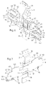
- la figure 1 est une vue en perspective, de l'extérieur, d'un répartiteur conforme à l'invention ;
- la figure 2 est une vue en perspective du répartiteur de la figure 1, montrant l'intérieur de ce répartiteur dont la paroi avant et l'un des flasques latéraux ont été ouverts ;
- la figure 3 est une vue isolée en perspective du bloc de connexion équipé des vis de serrage de ses bornes de sortie et de deux étriers ou cages à vis formant la borne d'entrée et une borne de sortie supplémentaire ;
- la figure 4 est une vue en perspective du bloc de connexion nu, sans les vis de serrage ni les étriers ou cages à vis ;
- la figure 5 est une vue en coupe par le plan V de la figure 4 ;
- les figures 6 et 7 sont des vues en perspective, respectivement des côtés intérieur et extérieur, du flan à plat à partir duquel est réalisé le boítier du répartiteur.
Claims (4)
- Répartiteur modulaire monopolaire pour la connexion de plusieurs conducteurs à un même potentiel comportant :caractérisé en ce que, la paroi avant (5) du boítier (1) présentant un décrochement ou nez (11) en saillie extérieure, le second côté (59) du bloc de connexion (50), duquel les têtes des vis de serrage (80, 81, 82) sont accessibles, présente une surface (60) en forme d'escalier à trois marches à chacune desquelles sont associées l'une des rangées de perçages de réception (67, 68, 69) et la rangée de vis de serrage (80, 81, 82) correspondante, avec une première marche (61, 64) qui est adjacente à la paroi arrière (4) du boítier (1) et qui est équipée de la borne d'entrée (78) et une dernière marche (63, 66) qui est reçue au moins partiellement dans le nez (11) de la paroi avant (5) du boítier (1), chacune des trois marches de la surface en escalier (60) du second côté (59) du bloc de connexion (50) présentant une face de contre-marche (64, 65, 66) sur laquelle débouche une seconde extrémité (73, 74, 75) des perçages de réception (67, 68, 69) d'une rangée associée, par laquelle ressortent les conducteurs, et une face de marche (61, 62, 63) sur laquelle sont accessibles les têtes de la rangée correspondante de vis de serrage (80, 81, 82).un boítier isolant (1) de forme globalement parallélépipédique possédant, sur quatre de ses côtés opposés deux à deux, deux flasques latéraux (2, 3), une paroi arrière (4) pourvue de moyens (10) pour son montage sur un rail de support et une paroi avant (5), et, sur ses deux autres côtés opposés, une ouverture d'entrée (7) pour la connexion au potentiel et une ouverture de sortie (8) pour le passage des conducteurs,et, à l'intérieur dudit boítier, un bloc conducteur de connexion (50) comportant, pour sa connexion au potentiel, une borne d'entrée (78) et, pour la connexion des différents conducteurs à ce bloc, une pluralité de bornes de sortie constituées par des perçages de réception (67, 68, 69) desdits conducteurs ménagés suivant une direction commune, sur trois rangées étagées, et dans chacun desquels débouche une vis de serrage transversale (80, 81, 82), chaque perçage ayant une première extrémité (70, 71, 72) d'introduction des conducteurs qui débouche d'un premier côté (51) du bloc de connexion (50) situé en regard de l'ouverture de sortie (8) du boítier (1), et les différentes vis de serrage (80, 81, 82) étant disposées, suivant une direction commune perpendiculaire à la direction commune des perçages de réception des conducteurs, sur trois rangées étagées correspondant aux trois rangées de perçages de réception des conducteurs, avec leurs têtes accessibles d'un second côté (59) du bloc de connexion (50) situé en regard de la paroi avant (5) du boítier (1),
- Répartiteur selon la revendication 1, caractérisé en ce que l'une au moins des faces de contre-marche (64, 65, 66) de la surface en escalier (60) du second côté (59) du bloc de connexion (50) est en dépouille par rapport à ce second côté.
- Répartiteur selon l'une des revendications précédentes, caractérisé en ce que le premier côté (51) du bloc de connexion (50), duquel débouche la première extrémité (70, 71, 72) des perçages de réception des conducteurs, présente également une surface en escalier (52) à trois marches présentant trois faces de marche (53, 54, 55) opposées aux faces de contre-marche (64, 65, 66) de la surface en escalier (60) du second côté (59) du bloc de connexion (50) et sur chacune desquelles débouche la première extrémité (70, 71, 72) d'une rangée correspondante de perçages de réception (67, 68, 69) des conducteurs.
- Répartiteur selon la revendication 3, caractérisé en ce que la face de dernière marche (55) de la surface en escalier (52) du premier côté (51) du bloc de connexion (50) est en contre-dépouille par rapport au second côté (59) de ce bloc.
Applications Claiming Priority (2)
| Application Number | Priority Date | Filing Date | Title |
|---|---|---|---|
| FR9915283 | 1999-12-03 | ||
| FR9915283A FR2802024B1 (fr) | 1999-12-03 | 1999-12-03 | Repartiteur modulaire monopolaire et bloc de connexion pour un tel repartiteur |
Publications (2)
| Publication Number | Publication Date |
|---|---|
| EP1107363A1 true EP1107363A1 (fr) | 2001-06-13 |
| EP1107363B1 EP1107363B1 (fr) | 2007-02-21 |
Family
ID=9552875
Family Applications (1)
| Application Number | Title | Priority Date | Filing Date |
|---|---|---|---|
| EP00403197A Expired - Lifetime EP1107363B1 (fr) | 1999-12-03 | 2000-11-16 | Répartiteur modulaire monopolaire |
Country Status (8)
| Country | Link |
|---|---|
| EP (1) | EP1107363B1 (fr) |
| AT (1) | ATE354875T1 (fr) |
| BR (1) | BR0005993A (fr) |
| DE (1) | DE60033488T2 (fr) |
| ES (1) | ES2281333T3 (fr) |
| FR (1) | FR2802024B1 (fr) |
| PL (1) | PL196785B1 (fr) |
| TR (1) | TR200003591A2 (fr) |
Cited By (3)
| Publication number | Priority date | Publication date | Assignee | Title |
|---|---|---|---|---|
| EP1587167A1 (fr) * | 2004-04-15 | 2005-10-19 | Erico International Corporation | Assemblage comprenant un bloc pour la distribution de courant fort |
| US7052333B2 (en) | 2004-04-15 | 2006-05-30 | Erico International Corporation | Power distribution block assembly |
| FR2958806A1 (fr) * | 2010-04-09 | 2011-10-14 | Auxel | Bloc de distribution unipolaire |
Families Citing this family (1)
| Publication number | Priority date | Publication date | Assignee | Title |
|---|---|---|---|---|
| HRP20120220B1 (hr) * | 2012-03-07 | 2015-01-30 | Majica, Antonio | Oklopljeni sabirniäśki blok |
Citations (6)
| Publication number | Priority date | Publication date | Assignee | Title |
|---|---|---|---|---|
| US3725851A (en) * | 1972-01-31 | 1973-04-03 | Underwriters Safety Device Co | Connector for high amperage applications |
| US5032092A (en) * | 1989-12-22 | 1991-07-16 | Connection Designs Corporation | Power distribution block |
| EP0772256A2 (fr) * | 1995-11-03 | 1997-05-07 | Legrand | Appareil électrique à bornes de raccordement protégées par un diaphragme à fixation par des ailes |
| EP0779678A1 (fr) * | 1995-12-12 | 1997-06-18 | Legrand | Connecteur pour câble électrique à raccorder à un élément conducteur, notamment pour câble électrique équipé d'un embout de câblage |
| EP0903808A1 (fr) * | 1997-09-18 | 1999-03-24 | Mecelec Industries | Connecteur pour conducteurs électriques et son procédé de fabrication |
| EP0961353A1 (fr) * | 1998-05-28 | 1999-12-01 | Legrand | Mécanisme de connexion, en particulier pour sortie de câble ou dérivation |
-
1999
- 1999-12-03 FR FR9915283A patent/FR2802024B1/fr not_active Expired - Fee Related
-
2000
- 2000-11-16 DE DE60033488T patent/DE60033488T2/de not_active Expired - Lifetime
- 2000-11-16 ES ES00403197T patent/ES2281333T3/es not_active Expired - Lifetime
- 2000-11-16 AT AT00403197T patent/ATE354875T1/de not_active IP Right Cessation
- 2000-11-16 EP EP00403197A patent/EP1107363B1/fr not_active Expired - Lifetime
- 2000-12-01 BR BR0005993-5A patent/BR0005993A/pt not_active IP Right Cessation
- 2000-12-01 PL PL344230A patent/PL196785B1/pl unknown
- 2000-12-01 TR TR2000/03591A patent/TR200003591A2/xx unknown
Patent Citations (6)
| Publication number | Priority date | Publication date | Assignee | Title |
|---|---|---|---|---|
| US3725851A (en) * | 1972-01-31 | 1973-04-03 | Underwriters Safety Device Co | Connector for high amperage applications |
| US5032092A (en) * | 1989-12-22 | 1991-07-16 | Connection Designs Corporation | Power distribution block |
| EP0772256A2 (fr) * | 1995-11-03 | 1997-05-07 | Legrand | Appareil électrique à bornes de raccordement protégées par un diaphragme à fixation par des ailes |
| EP0779678A1 (fr) * | 1995-12-12 | 1997-06-18 | Legrand | Connecteur pour câble électrique à raccorder à un élément conducteur, notamment pour câble électrique équipé d'un embout de câblage |
| EP0903808A1 (fr) * | 1997-09-18 | 1999-03-24 | Mecelec Industries | Connecteur pour conducteurs électriques et son procédé de fabrication |
| EP0961353A1 (fr) * | 1998-05-28 | 1999-12-01 | Legrand | Mécanisme de connexion, en particulier pour sortie de câble ou dérivation |
Cited By (5)
| Publication number | Priority date | Publication date | Assignee | Title |
|---|---|---|---|---|
| EP1587167A1 (fr) * | 2004-04-15 | 2005-10-19 | Erico International Corporation | Assemblage comprenant un bloc pour la distribution de courant fort |
| US7052333B2 (en) | 2004-04-15 | 2006-05-30 | Erico International Corporation | Power distribution block assembly |
| US7134921B2 (en) | 2004-04-15 | 2006-11-14 | Erico International Corporation | Power distribution block assembly |
| CN1684325B (zh) * | 2004-04-15 | 2010-09-15 | 爱瑞柯国际公司 | 配电板组件 |
| FR2958806A1 (fr) * | 2010-04-09 | 2011-10-14 | Auxel | Bloc de distribution unipolaire |
Also Published As
| Publication number | Publication date |
|---|---|
| EP1107363B1 (fr) | 2007-02-21 |
| FR2802024A1 (fr) | 2001-06-08 |
| TR200003591A3 (tr) | 2001-07-23 |
| ES2281333T3 (es) | 2007-10-01 |
| ATE354875T1 (de) | 2007-03-15 |
| DE60033488D1 (de) | 2007-04-05 |
| PL344230A1 (en) | 2001-06-04 |
| FR2802024B1 (fr) | 2002-02-22 |
| DE60033488T2 (de) | 2007-11-15 |
| TR200003591A2 (tr) | 2001-07-23 |
| PL196785B1 (pl) | 2008-01-31 |
| BR0005993A (pt) | 2001-07-17 |
Similar Documents
| Publication | Publication Date | Title |
|---|---|---|
| EP1119088B1 (fr) | Conduit de câblage électrique à multicompartiments présentant une grande capacité de câblage | |
| EP2299552B1 (fr) | Coffret destiné à recevoir un appareillage électrique basse tension associé à une cellule électrique moyenne tension | |
| EP1376638B1 (fr) | Ensemble de protection et de commande électromagnétique | |
| FR2824429A1 (fr) | Bloc modulaire a fusibles pour bornes | |
| FR2913525A1 (fr) | Boitier pour disjoncteur a trappe monobloc | |
| EP0109876B1 (fr) | Dispositif modulaire de distribution d'énergie électrique | |
| EP1107363B1 (fr) | Répartiteur modulaire monopolaire | |
| EP2383849B1 (fr) | Dispositif de raccordement électrique vertical | |
| EP1626467B1 (fr) | Peigne multipolaire de répartition horizontale d'une énergie électrique polyphasée et ensemble le comportant | |
| EP1422799B1 (fr) | Dispositif de distribution d'énergie pour appareillages électriques | |
| EP2849295B1 (fr) | Ensemble de distribution électrique comportant un peigne multipolaire de répartition d une énergie électrique. | |
| EP1655806A1 (fr) | Connecteur, grille de fausse coupure comprenant un tel connecteur et coffret de raccordement équipé d'une telle grille | |
| FR2637131A1 (fr) | Assemblage a utiliser avec des conducteurs electriques | |
| EP0589775B1 (fr) | Support isolant pour barres d'alimentation ou de distribution électrique | |
| FR3061351A1 (fr) | Appareil electrique comportant au moins une borne de connexion automatique | |
| EP0660461B1 (fr) | Socle multiple pour prise de courant | |
| EP1065749B1 (fr) | Accessoire de raccordement pour appareillages électriques, en particulier pour appareillages électriques modulaires. | |
| FR2802027A1 (fr) | Boitier d'appareillage electrique modulaire | |
| EP0629021A1 (fr) | Bornier de raccordement électrique de câbles d'alimentation en énergie électrique | |
| FR2800210A1 (fr) | Support pour le montage d'au moins un appareillage electrique sur une goulotte pour cables et/ou conducteurs. | |
| EP0076183A1 (fr) | Dispositif de distribution électrique | |
| FR2802025A1 (fr) | Bloc de connexion pour repartiteur monopolaire et repartiteur monopolaire comportant un tel bloc | |
| EP1039604A1 (fr) | Système de distribution d'énergie électrique dans les étages d'un immeuble | |
| FR2994346A1 (fr) | Capot d'hebergement de modules electriques a assemblage d'organe de connexion facilite | |
| FR2749708A1 (fr) | Borne d'arrivee pour barre d'alimentation en forme de peigne notamment pour appareils electriques modulaires |
Legal Events
| Date | Code | Title | Description |
|---|---|---|---|
| PUAI | Public reference made under article 153(3) epc to a published international application that has entered the european phase |
Free format text: ORIGINAL CODE: 0009012 |
|
| AK | Designated contracting states |
Kind code of ref document: A1 Designated state(s): AT DE ES GB IT TR |
|
| AX | Request for extension of the european patent |
Free format text: AL;LT;LV;MK;RO;SI |
|
| 17P | Request for examination filed |
Effective date: 20010711 |
|
| AKX | Designation fees paid |
Free format text: AT DE ES GB IT TR |
|
| RAP1 | Party data changed (applicant data changed or rights of an application transferred) |
Owner name: LEGRAND FRANCE Owner name: LEGRAND SNC |
|
| GRAP | Despatch of communication of intention to grant a patent |
Free format text: ORIGINAL CODE: EPIDOSNIGR1 |
|
| GRAS | Grant fee paid |
Free format text: ORIGINAL CODE: EPIDOSNIGR3 |
|
| GRAA | (expected) grant |
Free format text: ORIGINAL CODE: 0009210 |
|
| AK | Designated contracting states |
Kind code of ref document: B1 Designated state(s): AT DE ES GB IT TR |
|
| PG25 | Lapsed in a contracting state [announced via postgrant information from national office to epo] |
Ref country code: AT Free format text: LAPSE BECAUSE OF FAILURE TO SUBMIT A TRANSLATION OF THE DESCRIPTION OR TO PAY THE FEE WITHIN THE PRESCRIBED TIME-LIMIT Effective date: 20070221 |
|
| REG | Reference to a national code |
Ref country code: GB Ref legal event code: FG4D Free format text: NOT ENGLISH |
|
| REF | Corresponds to: |
Ref document number: 60033488 Country of ref document: DE Date of ref document: 20070405 Kind code of ref document: P |
|
| GBT | Gb: translation of ep patent filed (gb section 77(6)(a)/1977) |
Effective date: 20070523 |
|
| REG | Reference to a national code |
Ref country code: ES Ref legal event code: FG2A Ref document number: 2281333 Country of ref document: ES Kind code of ref document: T3 |
|
| PLBE | No opposition filed within time limit |
Free format text: ORIGINAL CODE: 0009261 |
|
| STAA | Information on the status of an ep patent application or granted ep patent |
Free format text: STATUS: NO OPPOSITION FILED WITHIN TIME LIMIT |
|
| 26N | No opposition filed |
Effective date: 20071122 |
|
| PGFP | Annual fee paid to national office [announced via postgrant information from national office to epo] |
Ref country code: IT Payment date: 20071022 Year of fee payment: 8 |
|
| PG25 | Lapsed in a contracting state [announced via postgrant information from national office to epo] |
Ref country code: IT Free format text: LAPSE BECAUSE OF NON-PAYMENT OF DUE FEES Effective date: 20081116 |
|
| PGFP | Annual fee paid to national office [announced via postgrant information from national office to epo] |
Ref country code: DE Payment date: 20091116 Year of fee payment: 10 |
|
| PGFP | Annual fee paid to national office [announced via postgrant information from national office to epo] |
Ref country code: GB Payment date: 20091118 Year of fee payment: 10 |
|
| GBPC | Gb: european patent ceased through non-payment of renewal fee |
Effective date: 20101116 |
|
| REG | Reference to a national code |
Ref country code: DE Ref legal event code: R119 Ref document number: 60033488 Country of ref document: DE Effective date: 20110601 Ref country code: DE Ref legal event code: R119 Ref document number: 60033488 Country of ref document: DE Effective date: 20110531 |
|
| PG25 | Lapsed in a contracting state [announced via postgrant information from national office to epo] |
Ref country code: DE Free format text: LAPSE BECAUSE OF NON-PAYMENT OF DUE FEES Effective date: 20110531 |
|
| PG25 | Lapsed in a contracting state [announced via postgrant information from national office to epo] |
Ref country code: GB Free format text: LAPSE BECAUSE OF NON-PAYMENT OF DUE FEES Effective date: 20101116 |
|
| PGFP | Annual fee paid to national office [announced via postgrant information from national office to epo] |
Ref country code: TR Payment date: 20141023 Year of fee payment: 15 |
|
| PGFP | Annual fee paid to national office [announced via postgrant information from national office to epo] |
Ref country code: ES Payment date: 20151019 Year of fee payment: 16 |
|
| PG25 | Lapsed in a contracting state [announced via postgrant information from national office to epo] |
Ref country code: TR Free format text: LAPSE BECAUSE OF NON-PAYMENT OF DUE FEES Effective date: 20151116 |
|
| PG25 | Lapsed in a contracting state [announced via postgrant information from national office to epo] |
Ref country code: ES Free format text: LAPSE BECAUSE OF FAILURE TO SUBMIT A TRANSLATION OF THE DESCRIPTION OR TO PAY THE FEE WITHIN THE PRESCRIBED TIME-LIMIT Effective date: 20070221 |
|
| REG | Reference to a national code |
Ref country code: ES Ref legal event code: FD2A Effective date: 20180627 |
|
| PG25 | Lapsed in a contracting state [announced via postgrant information from national office to epo] |
Ref country code: ES Free format text: LAPSE BECAUSE OF FAILURE TO SUBMIT A TRANSLATION OF THE DESCRIPTION OR TO PAY THE FEE WITHIN THE PRESCRIBED TIME-LIMIT Effective date: 20161117 |