EP1106855A2 - Annular friction-clutch facing for a multi-disk clutch - Google Patents
Annular friction-clutch facing for a multi-disk clutch Download PDFInfo
- Publication number
- EP1106855A2 EP1106855A2 EP00126063A EP00126063A EP1106855A2 EP 1106855 A2 EP1106855 A2 EP 1106855A2 EP 00126063 A EP00126063 A EP 00126063A EP 00126063 A EP00126063 A EP 00126063A EP 1106855 A2 EP1106855 A2 EP 1106855A2
- Authority
- EP
- European Patent Office
- Prior art keywords
- grooves
- group
- facing
- clutch
- disk
- Prior art date
- Legal status (The legal status is an assumption and is not a legal conclusion. Google has not performed a legal analysis and makes no representation as to the accuracy of the status listed.)
- Granted
Links
- 239000000314 lubricant Substances 0.000 claims abstract description 12
- 230000001154 acute effect Effects 0.000 claims 3
- 230000005540 biological transmission Effects 0.000 description 20
- 239000010687 lubricating oil Substances 0.000 description 20
- 230000008901 benefit Effects 0.000 description 10
- 239000003921 oil Substances 0.000 description 7
- 238000005461 lubrication Methods 0.000 description 4
- 238000005086 pumping Methods 0.000 description 4
- 238000010521 absorption reaction Methods 0.000 description 3
- 230000008859 change Effects 0.000 description 3
- 239000000463 material Substances 0.000 description 3
- 229910000831 Steel Inorganic materials 0.000 description 2
- 230000015572 biosynthetic process Effects 0.000 description 2
- 238000002485 combustion reaction Methods 0.000 description 2
- 238000006073 displacement reaction Methods 0.000 description 2
- 230000000694 effects Effects 0.000 description 2
- 238000004519 manufacturing process Methods 0.000 description 2
- 239000010959 steel Substances 0.000 description 2
- 238000003860 storage Methods 0.000 description 2
- 235000012773 waffles Nutrition 0.000 description 2
- 230000000712 assembly Effects 0.000 description 1
- 238000000429 assembly Methods 0.000 description 1
- 239000000969 carrier Substances 0.000 description 1
- 230000015556 catabolic process Effects 0.000 description 1
- 230000002950 deficient Effects 0.000 description 1
- 239000002657 fibrous material Substances 0.000 description 1
- 238000009434 installation Methods 0.000 description 1
- 238000013532 laser treatment Methods 0.000 description 1
- 230000001050 lubricating effect Effects 0.000 description 1
- 230000007246 mechanism Effects 0.000 description 1
- 239000002184 metal Substances 0.000 description 1
- 238000000034 method Methods 0.000 description 1
- 230000004048 modification Effects 0.000 description 1
- 238000012986 modification Methods 0.000 description 1
- 239000000126 substance Substances 0.000 description 1
Images


Classifications
-
- F—MECHANICAL ENGINEERING; LIGHTING; HEATING; WEAPONS; BLASTING
- F16—ENGINEERING ELEMENTS AND UNITS; GENERAL MEASURES FOR PRODUCING AND MAINTAINING EFFECTIVE FUNCTIONING OF MACHINES OR INSTALLATIONS; THERMAL INSULATION IN GENERAL
- F16D—COUPLINGS FOR TRANSMITTING ROTATION; CLUTCHES; BRAKES
- F16D25/00—Fluid-actuated clutches
- F16D25/06—Fluid-actuated clutches in which the fluid actuates a piston incorporated in, i.e. rotating with the clutch
- F16D25/062—Fluid-actuated clutches in which the fluid actuates a piston incorporated in, i.e. rotating with the clutch the clutch having friction surfaces
- F16D25/063—Fluid-actuated clutches in which the fluid actuates a piston incorporated in, i.e. rotating with the clutch the clutch having friction surfaces with clutch members exclusively moving axially
- F16D25/064—Fluid-actuated clutches in which the fluid actuates a piston incorporated in, i.e. rotating with the clutch the clutch having friction surfaces with clutch members exclusively moving axially the friction surface being grooved
-
- F—MECHANICAL ENGINEERING; LIGHTING; HEATING; WEAPONS; BLASTING
- F16—ENGINEERING ELEMENTS AND UNITS; GENERAL MEASURES FOR PRODUCING AND MAINTAINING EFFECTIVE FUNCTIONING OF MACHINES OR INSTALLATIONS; THERMAL INSULATION IN GENERAL
- F16D—COUPLINGS FOR TRANSMITTING ROTATION; CLUTCHES; BRAKES
- F16D13/00—Friction clutches
- F16D13/58—Details
- F16D13/60—Clutching elements
- F16D13/64—Clutch-plates; Clutch-lamellae
- F16D13/648—Clutch-plates; Clutch-lamellae for clutches with multiple lamellae
-
- F—MECHANICAL ENGINEERING; LIGHTING; HEATING; WEAPONS; BLASTING
- F16—ENGINEERING ELEMENTS AND UNITS; GENERAL MEASURES FOR PRODUCING AND MAINTAINING EFFECTIVE FUNCTIONING OF MACHINES OR INSTALLATIONS; THERMAL INSULATION IN GENERAL
- F16D—COUPLINGS FOR TRANSMITTING ROTATION; CLUTCHES; BRAKES
- F16D25/00—Fluid-actuated clutches
- F16D25/12—Details not specific to one of the before-mentioned types
- F16D25/123—Details not specific to one of the before-mentioned types in view of cooling and lubrication
Definitions
- the present invention relates, generally, to multi-disk devices. More specifically, the present invention relates to friction facings for multi-disk devices having improved lubrication characteristics.
- Multi-disk friction devices are employed in a wide range of applications as clutches or brakes. For example, such devices are frequently used in land-based vehicles. Generally speaking, such vehicles require three basic components: a power plant (such as an intemal-combustion engine), a powertrain, and wheels. The powertrain's main component is typically referred to as the "transmission.” Engine torque and speed are converted in the transmission in accordance with the tractive-power demand of the vehicle.
- a power plant such as an intemal-combustion engine
- the powertrain's main component is typically referred to as the "transmission.”
- Engine torque and speed are converted in the transmission in accordance with the tractive-power demand of the vehicle.
- Transmissions include one or more gear sets, each of which may include an inner sun-gear, intermediate planet gears supported by their carriers, and outer ring-gears. Various components of each gear set are held or powered to change the gear ratios in the transmission.
- the multi-disk pack-clutch is a friction device that is commonly employed as a holding mechanism in a transmission or differential.
- multi-disk friction devices also find use in industrial applications, such as wet brakes for braking the wheels on earth-moving equipment.
- the multi-disk pack-clutch or brake-assembly includes a plurality of ring-shaped disks and has a clutch subassembly.
- the subassembly includes a set of plates arranged in a torsionally rigid manner and fixed against displacement on a disk carrier as well as a set of friction disks interleaved between one another and fixed against displacement on a hub.
- the clutch or brake assembly also typically includes a piston. When a component of a gear set is to be held, as during a particular gear range, a piston is actuated to cause the plates and friction disks to come in contact with one another. The plates mutually engage in a gearing manner, and the friction disks mutually engage in a gearing manner.
- the gear sets are mutually displaceable relative to each other in an axial direction and can be brought into and out of engagement in pairs.
- "open pack” operation the plates and friction disks normally turn past one another without contact.
- several multi-disk friction devices in combination to establish different drive connections throughout the transmission or differential to provide various gear ratios in operation or to brake a component.
- Multi-disk clutches or multi-disk brakes having disks that are interconnected, i.e., made in a single piece from frictional material, are also known in the related art. Examples of such devices are disclosed in DE 31 49 880 C2, DE 35 32 759 C1, and DE 31 18 565 Al.
- Each friction disk includes a carrier plate made of, for instance, steel.
- the plate includes a friction surface on at least one annular face of the plate.
- the friction surface generally includes a fiber material manufactured from paper or a paper-like material.
- the structure of the plate surfaces is generally smooth. The confronting faces of the interleaved plates and friction disks are, therefore, covered with friction surfaces.
- WO 97/32678 discloses a special plate-surface structure made of steel and used to improve the coefficient of friction in the pairings of the friction disks and plates.
- lubrication of the individual components plays an important role. It must be ensured, in particular, that lubricating oil reaches the friction surfaces of the disks. For this purpose, lubricating oil is typically sprayed onto the friction surfaces. High temperatures are maintained, to the extent possible, within limits by the lubricating oil.
- a multi-disk friction device such as a clutch or brake-the service life of which is increased as compared with known units and breakdowns of the disks of which are avoided.
- the present invention arranges the disks such that lubrication is optimized so that they transmit torque in an improved manner.
- the present invention overcomes the disadvantages in the related art in an annular friction-clutch facing for a multi-disk clutch.
- the facing includes an inner edge and an outer edge defining a width of the facing.
- the facing further includes a first group of grooves formed on the facing and having a first cross-sectional area. Each groove of the first group has a first opening at the outer edge and a second opening at the inner edge remote from the first opening and is adapted to direct lubricating agents across the width over a substantial area of the facing.
- the facing further includes a second group of grooves formed on the facing and having a second cross-sectional area smaller than the first cross-sectional area.
- the second group of grooves includes first and second sets of grooves. The grooves of the first set are disposed in intersecting relationship with the grooves of the second set. The second group of grooves is adapted to remove excess of the lubricating agents on the facing.
- one advantage of the present invention is that the friction facings are provided with grooves that ensure that the working face is provided with a residual supply of lubricating oil.
- Another advantage of the present invention is that the grooves discharge the heat incurred during the "closed pack" operating mode of the friction device.
- Another advantage of the present invention is that the grooves improve the friction properties of the multi-disk friction device.
- Another advantage of the present invention is that relatively large streams of lubricating oil flow in the grooves, thereby substantially improving the way frictional heat is carried off within the clutch and, thus, contributing to the increased service life of the disks.
- Another advantage of the present invention is that the grooves entirely wet the friction surfaces with lubricating oil by supplying remote areas of the disks with lubricating oil at all speeds occurring during operation of the disks.
- Another advantage of the present invention is that the grooves counteract the formation of a film by the lubricating oil.
- Another advantage of the present invention is that energy density is increased considerably-the size of the disks can be reduced while maintaining the frictional work, or the frictional work can be increased by maintaining the size of the disks.
- Another advantage of the present invention is that the streams of lubricating oil within the grooves do not obstruct the absorption of load upon engagement of the disks such that no time delay occurs.
- a multi-disk friction device such as a clutch or brake assembly
- the friction device 10 is adapted to be employed in connection with a transmission, differential, or brake system.
- transmission assemblies of transmission systems typically include an input shaft that is operatively coupled to a prime mover, such as an internal-combustion engine.
- the transmission assembly also includes an output shaft that is operatively coupled to driven wheels through other drive-train components, such as a drive shaft and an axle having a differential.
- At least one gear set (often, a plurality of gear sets) is operatively coupled between the input and output shafts.
- a transmission casing supports the input and output shafts and gear sets of the transmission assembly.
- the transmission assembly will typically include at least one friction device 10.
- the transmission assembly may employ any number of friction devices adapted to hold or power the gear sets to change the gear ratio of the transmission.
- the present invention may be employed in a transmission, differential, or brake system whether used in an automotive, non-automotive, or industrial application.
- clutch is used below in any context, this term should be given its broadest possible meaning, including, but not limited to, clutches and brakes for use in transmission, differential, or braking systems of all types.
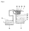
- the friction device, or clutch assembly 10 is provided with a drive member, generally indicated at 12, and a driven member, generally indicated at 14.
- the drive member 12 includes a drive shaft 16.
- Figure 1 shows the drive shaft 16 rigidly connected to a disk carrier 18 for rotation of the drive shaft 16 and the disk carrier 18 about axis "A" as will be described in greater detail below.
- the driven member 14 includes a driven shaft 17 and a driven hub 26.
- the driven hub 26 may include axially extending splines 20 disposed about the annular periphery of the driven hub 26.
- a plurality of annular, outer drive disks 22 are splined or otherwise mounted at 24 for movement in the axial direction relative to the disk carrier 18 and are supported by 24 for rotation about axis "A.”
- a plurality of annular, inner driven disks 28 are splined or otherwise mounted to and carried by the splines 20 for rotation about axis "B.”
- the outer drive disks 22 and the inner driven disks 28 are interleaved and rotate past one another when the clutch 10 is in "open pack” mode as is commonly known in the art.
- Each disk 22, 28 includes a working face having a predetermined thickness and can be brought into engagement with a working face of an adjacent disk 22, 28 to transmit a torque to the adjacent disk 22, 28.
- the working faces include a treated surface that frictionally engages a like surface on the adjacent disk 22,28 as will be described in greater detail below.
- each disk 22, 28 is made of metal.
- the working faces of the disks 22, 28 are provided with an annular friction-clutch facing, generally indicated at 30 in Figures 2a, 2b, 2c, and 3, where like numerals, some of which have been increased by a factor of 100, are used to designate like structure.
- the friction-clutch facing 30 is made of a paper-like substance. Each facing 30 cooperates in an engaged state with the working face of an adjacent disk 22, 28.
- the working faces are bathed with a lubricating agent, such as oil, forming an oil film (not shown).
- each facing 30 includes an inner edge 32 and an outer edge 34 defining a width (w) of the facing 30.
- the facing 30 further includes a first group of grooves 36 formed on the facing 30 and having a first cross-sectional area.
- Each groove of the first group 36 has a first opening 38 at the outer edge 34 and a second opening 40 at the inner edge 32 remote from the first opening 38.
- the grooves of the first group 36 are adapted to direct lubricating agents across the width (w) over a substantial area of the facing 30.
- the facing 30 further includes a second group of grooves 42 formed on the facing 30 and having a second cross-sectional area smaller than the first cross-sectional area.
- the second group of grooves 42 includes a first set of grooves 44 and a second set of grooves 46.
- the grooves of the first set 44 are disposed in intersecting relationship with the grooves of the second set 46.
- the second group of grooves 42 is adapted to remove excess of the lubricating agents on the facing 30.
- the grooves of the first group 36 can be designed to have many orientations, like radials or secants.
- the grooves of the first group 36 extend radially across the width (w) such that each of the grooves of the first group 36 defines a continuously changing angle with respect to a line defining a diameter D 1 of the facing.
- one groove 36 is shown extended at a 40° angle in Figure 2a and at a 30° angle in Figure 3 with respect to a diameter D 1 of the facing 30.
- the angle of each other groove 36 relative to the diameter D 1 changes.
- grooves of the first group 36 may be spaced unevenly from other grooves of the first group 36.
- the first groove 36 is spaced 10° with respect to the diameter D 2 .
- Three other grooves 36 are also shown extending radially across the width (w) at 23°, 34°, and 45°, respectively, from the diameter D 2 .
- the grooves of the first group 136 are spaced in equal increments relative to adjacent grooves 136 and extend arcuately across the width (w) of the facing 30. In this manner, the grooves 136 are shaped similarly to the curve of pump blades. The curve of the grooves 136 is to be adjusted to follow the direction of rotation of the facing 30. In the embodiment of Figure 2b, the direction of rotation of the facing 30 is counter-clockwise.
- the first group of grooves 236 includes a first predetermined sub-group of grooves 248 that extend arcuately in one direction across the width (w) and are spaced in equal increments relative to adjacent grooves 248 and a second predetermined sub-group of grooves 250 that extend arcuately in a direction opposite to that of the grooves 248 across the width (w) and are spaced in equal increments relative to adjacent grooves 250.
- the grooves 248, 250 are arranged independently of the direction of rotation of the facing 30.
- Each of these preferred embodiments also includes a second group of grooves 42 that, in turn, includes a first and second set of grooves 44, 46.
- the grooves of the first set 44 are disposed in parallel relationship with each other, extend radially across the width (w), and are disposed in perpendicular relationship, or at 90°, to the grooves of the second set 46.
- the second group of grooves 42 is arranged in a meshwork or grating manner. This could also be referred to as a "waffle" pattern.
- the grooves of the first set 44 can deviate from extending radially across the width (w) and intersect the grooves of the second set 46 at any angle.
- the grooves of the first and second sets, 44, 46, respectively, are not deeply formed in the facing 30, either.
- adjacent grooves of the first group 36, 136, 236 are disposed one to the other at a first spaced increment
- adjacent grooves of the second group 42 are disposed one to the other at a second spaced increment that is smaller than the increment between the grooves of the first group 36.
- the first group of grooves 36, 136, 236 as well as the second group of grooves 42 can have various relative sizes and shapes.
- the grooves of the first group 36, 136, 236 can be formed deeply within the facing 30 and may define sharp edges on the facing 30.
- the facing 30 defines a depth
- the grooves of the first group 36, 136, 236 are defined into the depth to a greater extent than the grooves of the second group 42 are defined into the depth.
- the grooves of the first group 36, 136, 236 are twice as deep as the grooves of the second group 42.
- the depth of the grooves 36, 136, 236 can be greater by any multiple of the depth of the grooves 42.
- the grooves of the first group 36, 136, 236 are even formed entirely through the depth of the facing 30.
- the grooves of the second group 42 have a second predetermined width
- the grooves of the first group 36, 136, 236 have a first predetermined width that is substantially greater than the second predetermined width.
- the width of the grooves of the first group 36, 136, 236 is twice as great as the width of the grooves of the second group 42.
- the width of the grooves 36, 136, 236 can be greater by any multiple of the width of the grooves 42.
- the number of grooves of the second group 42 is greater than the number of grooves of the first group 36, 136, 236.
- the grooves are formed on at least one, and preferably all, of the facings 30 for the storage of lubricating agents. Those having ordinary skill in the art will appreciate from the description herein that the grooves may be formed on either one of or both adjacent sides of adjacent disks 22, 28.
- the structure of the facings 30 can be produced by any method for applying or removing material, including mechanical means. Non-mechanical means are also possible to achieve the desired structure of the grooves. A laser treatment of the facings 30 may also be employed.
- the first group of grooves 36, 136, 236 is arranged and disposed in such a way that a pumping effect is produced.
- the grooves of the first group 36, 136, 236 are also provided with a relatively large cross-section such that large quantities of lubricating oil can be conveyed.
- the lubricating oil is, thus, effectively circulated by the first group of grooves such that the lubricating oil covers the entire surface of the disks 22, 28.
- the second group of grooves 42 is used to remove excessive lubricating oil and, thus, reduce hydrodynamic effects that could lead to "floating" of the facings 30 on the oil film.
- the grooves 36, 136, 236, 42 ensure that the facings 30 of the disks 22, 28 are provided with a residual supply of lubricating oil and prevent any dry running in the contact zone between the inner disks 22, 28.
- the grooves 36, 136, 236, 42 lead to improvements of the friction properties of the facings 30 and, thus, the disks 22, 28, including constancy of the coefficient of friction and power absorption during the shifting operation. Furthermore, with the facings 30 of the kind discussed above, the grooves 36, 136, 236, 42 can be made to allow for a particular oil flow or catch oil in limited areas of the disk 22, 28 such that the heat incurred during the work of the friction device 10 is discharged.
- the grooves 36, 136, 236, 42 discharge the heat incurred during the "closed pack" operating mode and, thus, improve the friction properties of the friction device 10. Relatively large streams of lubricating oil flow in the grooves 36, 136, 236, 42, thereby substantially improving the way frictional heat is carried off within the clutch 10 and, thus, contributing to the increased service life of the disks 22, 28.
- the grooves 36, 136, 236, 42 entirely wet the facings 30 with lubricating oil by supplying remote areas of the disks 22, 28 with lubricating oil at all speeds occurring during operation of the disks 22, 28.
- the grooves 36, 136, 236, 42 counteract the formation of a film by the lubricating oil.
- Figure 4 shows another embodiment of the present invention.
- Ring-shaped facing L is as well based on a ring-shaped disk carrier T having a friction lining R.
- Friction lining R shows two groups of grooves, the second group of grooves - waffle grooves as they are called - which are formed by parallely extending grooves 20, parallely extending grooves 30 - as known already - as well as the first group of grooved - pumping grooves as they are called.
- first group of grooves there are three variations of the first group of grooves (pumping grooves).
- a first group of grooves of the first kind 10a which are radially arranged on the periphery of the ring-shaped disk carrier T and the position of which is offset from center M of the ring-shaped disk carrier T and which extend at an angle ⁇ to radius r of the ring-shaped disk carrier.
- the first group of grooves of the second/third or further kind 10b and lOc differ from the first group of grooves of the first kind 10a in that they extend at angles ⁇ and ⁇ to radius r of the ring-shaped disk carrier T, with angles ⁇ and ⁇ being different from angle ⁇ .
Landscapes
- Engineering & Computer Science (AREA)
- General Engineering & Computer Science (AREA)
- Mechanical Engineering (AREA)
- Mechanical Operated Clutches (AREA)
Abstract
Description
Claims (22)
- An annular friction-clutch facing (30) for a multi-disk clutch (10) comprising:an inner edge (32) and an outer edge (34) defining a width (w) of said facing (30);a first group of grooves (136, 236) formed on said facing (30) and having a first cross-sectional area, each groove of said first group (136, 236) having a first opening (38) at said outer edge (34) and a second opening (40) at said inner edge (32) remote from said first opening (38) and adapted to direct lubricating agents across said width (w) over a substantial area of said facing (30); anda second group of grooves (42) formed on said facing (30) and having a second cross-sectional area smaller than said first cross-sectional area, said second group of grooves (42) including first and second sets of grooves (44, 46), the grooves of said first set (44) being disposed in intersecting relationship with the grooves of said second set (46), said second group of grooves (42) adapted to remove excess of the lubricating agents on said facing (30).
- An annular friction-clutch facing (30) for a multi-disk clutch (10) as set forth in claim 1, wherein the grooves of said first group (36) extend radially across said width (w) such that each of the grooves of said first group (36) defines a continuously changing angle with respect to a diameter D1 of said facing (30).
- An annular friction-clutch facing (30) for a multi-disk clutch (10) as set forth in claim 1, wherein the grooves of said first group (136) are spaced in equal increments relative to adjacent grooves (136) and extend arcuately across said width (w) of said facing (30).
- An annular friction-clutch facing (30) for a multi-disk clutch (10) as set forth in claim 1, wherein said first group of grooves (236) includes a first predetermined sub-group of grooves (248) that extend arcuately in one direction across said width (w) and are spaced in equal increments relative to adjacent grooves of said first predetermined sub-group (248) and a second predetermined sub-group of grooves (250) that extend arcuately in a direction opposite to that of the grooves of said first predetermined sub-group (248) across said width (w) and are spaced in equal increments relative to adjacent grooves of said second predetermined sub-group (250).
- An annular friction-clutch facing (30) for a multi-disk clutch (10) as set forth in claim 1, wherein the grooves of said first set (44) are disposed in parallel relationship with each other.
- An annular friction-clutch facing (30) for a multi-disk clutch (10) as set forth in claim 1, wherein the grooves of said first set (44) extend radially across said width (w).
- An annular friction-clutch facing (30) for a multi-disk clutch (10) as set forth in claim 1, wherein the grooves of said first set (44) are disposed in perpendicular relationship to the grooves of said second set (46).
- An annular friction-clutch facing (30) for a multi-disk clutch (10) as set forth in claim 1, wherein adjacent grooves of said first group (136, 236) are disposed one to the other at a first spaced increment and adjacent grooves of said second group (42) are disposed one to the other at a second spaced increment that is smaller than the first spaced increment.
- An annular friction-clutch facing (30) for a multi-disk clutch (10) as set forth in claim 1, wherein said facing (30) defines a depth and the grooves of said first group (136, 236) are defined into said depth to a greater extent than the grooves of said second group (42) are defined into said depth.
- An annular friction-clutch facing (30) for a multi-disk clutch (10) as set forth in claim 9, wherein the grooves of said first group (136, 236) are twice as deep as the grooves of said second group (42).
- An annular friction-clutch facing (30) for a multi-disk clutch (10) as set forth in claim 9, wherein the grooves of said first group (136, 236) are formed entirely through said depth of said facing (30).
- An annular friction-clutch facing (30) for a multi-disk clutch (10) as set forth in claim 1, wherein the grooves of said second group (42) have a second predetermined width and the grooves of said first group (136, 236) have a first predetermined width that is substantially greater than the second predetermined width.
- An annular friction-clutch facing (30) for a multi-disk clutch (10) as set forth in claim 12, wherein the width of the grooves of said first group (136, 236) is twice as great as the width of the grooves of said second group (42).
- An annular friction-clutch facing (10a) as set forth in claim 1, wherein the first group of grooves of the first kind are provided for which are radially arranged on the periphery of the ring-shaped disk carrier T and which are set off from the center M of the ring-shaped disk carrier and which extend in a first acute angle α to radius r of the disk carrier T and wherein at least a further first group of grooves of second (10b) and/or third (10c) and/or a further kind are provided for which are radially arranged on the periphery of the disk carrier T, which are set off from the center M of the disk carrier T and which extend to the radius r of the disk carrier T at a second and third or further acute angle β or γ which is different to the first acute angle α.
- An annular friction clutch facing (10) as set forth in claim 1, wherein the first group of grooves of the first kind are provided for which extend along radial lines, sectants or arcs as well as the first group of grooves of the second kind which extend along radial lines, sectants or arcs and/or the first group of grooves of a third or a further kind which extend along radial lines, sectants or arcs.
- An annular friction-clutch facing (30) for a multi-disk clutch (10) as set forth in claim 1, wherein the number of grooves of said second group (42) is greater than the number of grooves of said first group (136, 236).
- A multi-disk friction device (10) comprising:a drive member (12) having a plurality of drive disks (22) supported for rotation with said drive member (12) and a driven member (14) having a plurality of driven disks (28) supported for rotation with said driven member (14), said drive and driven disks (22, 28) interleaved relative to each other such that each drive disk (22) is adjacent a driven disk (28) and moveable toward and away from one another for providing selective frictional engagement therebetween and to transmit torque between said drive and driven members (12, 14);each of said drive and driven disks (22, 28) including an annular facing (30) that is disposed for frictional engagement with annular facings (30) of an adjacent one of said disks (22, 28), at least one of said annular facings (30) on said adjacent one of said disks (22, 28) including an inner edge (32) and an outer edge (34) defining a width (w) of said facing (30), a first group of grooves (136, 236) formed on said facing (30) having a first relatively larger cross-sectional area, each groove of said first group (136, 236) having an opening (38) at said outer edge (34) and an opening (40) at said inner edge (32) remote from said other opening (38) and adapted to direct lubricating agents across said width (w) over a substantial area of said facing (30), and a second group of grooves (42) formed on said facing (30) having a second smaller cross-sectional area relative to said first group of grooves (136, 236), said second group of grooves (42) including first and second sets of grooves (44, 46), the grooves of said first set (44) being disposed in intersecting relationship with the grooves of said second set (46), with said second group of grooves (42) adapted to remove excess of the lubricating agents on said facing (30).
- A multi-disk friction device (10) as set forth in claim 15, wherein the grooves of said first group (36) extend radially across said width (w) such that each of the grooves of said first group (36) defines a continuously changing angle with respect to a diameter D1 of said facing (30).
- A multi-disk friction device (10) as set forth in claim 15, wherein the grooves of said first group (136) are spaced in equal increments relative to adjacent grooves (136) and extend arcuately across said width (w) of said facing (30).
- A multi-disk friction device (10) as set forth in claim 15, wherein said first group of grooves (236) includes a first predetermined sub-group of grooves (248) that extend arcuately in one direction across said width (w) and are spaced in equal increments relative to adjacent grooves of said first predetermined sub-group (248) and a second predetermined sub-group of grooves (250) that extend arcuately in a direction opposite to that of the grooves of said first predetermined sub-group (248) across said width (w) and are spaced in equal increments relative to adjacent grooves of said second predetermined sub-group (250).
- A multi-disk friction device (10) as set forth in claim 15, wherein the grooves of said first set (44) are disposed in parallel relationship with each other.
- A multi-disk friction device (10) as set forth in claim 15, wherein the grooves of said first set (44) extend radially across said width (w).
Applications Claiming Priority (3)
| Application Number | Priority Date | Filing Date | Title |
|---|---|---|---|
| DE19957511A DE19957511A1 (en) | 1999-11-30 | 1999-11-30 | Slat for a power transmission unit, for example for a clutch |
| DE19957511 | 1999-11-30 | ||
| US09/702,447 US6454072B1 (en) | 1999-11-30 | 2000-10-31 | Annular friction-clutch facing for a multi-disk clutch |
Publications (3)
| Publication Number | Publication Date |
|---|---|
| EP1106855A2 true EP1106855A2 (en) | 2001-06-13 |
| EP1106855A3 EP1106855A3 (en) | 2001-10-17 |
| EP1106855B1 EP1106855B1 (en) | 2006-12-20 |
Family
ID=26055675
Family Applications (1)
| Application Number | Title | Priority Date | Filing Date |
|---|---|---|---|
| EP00126063A Expired - Lifetime EP1106855B1 (en) | 1999-11-30 | 2000-11-29 | Annular friction-clutch facing for a multi-disk clutch |
Country Status (4)
| Country | Link |
|---|---|
| US (1) | US6454072B1 (en) |
| EP (1) | EP1106855B1 (en) |
| JP (1) | JP2001187927A (en) |
| DE (1) | DE19957511A1 (en) |
Cited By (3)
| Publication number | Priority date | Publication date | Assignee | Title |
|---|---|---|---|---|
| WO2013060313A1 (en) * | 2011-10-24 | 2013-05-02 | Schaeffler Technologies AG & Co. KG | Method for machining a metallic frictional surface using lasers; and a corresponding sheet-metal part |
| ES2556541A1 (en) * | 2014-07-18 | 2016-01-18 | Wartsila Ibérica, S.A. | Method of treatment of metallic, ceramic or stone surfaces and surface obtainable with said method (Machine-translation by Google Translate, not legally binding) |
| CN111486183A (en) * | 2020-04-20 | 2020-08-04 | 北京理工大学 | A wet multi-plate shift clutch |
Families Citing this family (20)
| Publication number | Priority date | Publication date | Assignee | Title |
|---|---|---|---|---|
| ATE370346T1 (en) * | 2001-03-02 | 2007-09-15 | Zf Sachs Ag | CLUTCH ARRANGEMENT |
| US7014024B2 (en) * | 2003-06-11 | 2006-03-21 | Sulzer Euroflamm Us Inc. | System and method for improving cooling in a friction facing environment |
| DE10342271B4 (en) * | 2003-09-12 | 2014-07-10 | Zf Friedrichshafen Ag | Friction lining plate |
| US7168544B2 (en) * | 2003-10-02 | 2007-01-30 | Sulzer Euroflamm Us Inc. | Friction facing material for use in a friction environment |
| US7069636B2 (en) | 2003-10-02 | 2006-07-04 | Euroflamm Select Inc. | Friction facing method for use in a friction environment |
| US20060236523A1 (en) * | 2003-10-02 | 2006-10-26 | Sulzer Euroflamm Us Inc | Friction facing method for use in a friction environment |
| DE502004005292D1 (en) | 2004-12-15 | 2007-11-29 | Borgwarner Inc | Slat for power transmission unit and power transmission unit with lamella |
| US20070000747A1 (en) * | 2005-06-28 | 2007-01-04 | Tomoyuki Miyazaki | Wet clutch friction plate and multiple disc friction clutch apparatus |
| JP2007040525A (en) * | 2005-06-28 | 2007-02-15 | Nsk Warner Kk | Wet clutch friction plate and multiple disc friction clutch apparatus |
| JP2007040526A (en) * | 2005-06-28 | 2007-02-15 | Nsk Warner Kk | Wet clutch friction plate and multiple disc friction clutch apparatus |
| US20070270069A1 (en) * | 2006-05-18 | 2007-11-22 | Sulzer Euroflamm Us Inc. | Friction material and system and method for making the friction material |
| DE102006031035A1 (en) | 2006-07-05 | 2008-01-10 | Zf Friedrichshafen Ag | Friction disc for a wet-running clutch for a vehicle |
| DE102007006164A1 (en) * | 2007-02-07 | 2008-08-14 | Siemens Ag | Friction brake with a provided between two brake elements contact surface |
| JP2008309317A (en) * | 2007-06-18 | 2008-12-25 | Aisin Aw Co Ltd | Starter |
| JP5143925B2 (en) * | 2011-04-25 | 2013-02-13 | 株式会社エクセディ | Friction member, clutch plate, clutch device, and torque converter |
| US9022183B2 (en) * | 2013-07-26 | 2015-05-05 | Deere And Company | Self-centering wet clutch or brake plate |
| DE102014225654A1 (en) | 2014-12-12 | 2016-06-16 | Schaeffler Technologies AG & Co. KG | Friction lining, in particular clutch lining |
| DE102015122200B4 (en) | 2015-12-18 | 2022-09-08 | Chr. Mayr Gmbh + Co. Kg | Quiescent current brake with improved counter-friction surface due to laser processing of the same |
| CN108138860B (en) * | 2016-02-16 | 2020-08-14 | 吉凯恩传动系统日本株式会社 | Multi-plate clutch |
| AT522252B1 (en) * | 2019-03-13 | 2022-06-15 | Miba Frictec Gmbh | friction assembly |
Citations (4)
| Publication number | Priority date | Publication date | Assignee | Title |
|---|---|---|---|---|
| DE3118565A1 (en) | 1981-05-11 | 1982-11-25 | Zahnradfabrik Friedrichshafen Ag, 7990 Friedrichshafen | Multi-disc clutch |
| DE3149880C2 (en) | 1980-12-19 | 1985-07-04 | Nissan Motor Co., Ltd., Yokohama, Kanagawa | Pressure fluid operated multi-plate clutch |
| DE3532759C1 (en) | 1985-09-13 | 1987-03-05 | Daimler Benz Ag | Multi-plate clutch with a ring cylinder and means for fixing its position relative to an outer plate carrier |
| WO1997032678A1 (en) | 1996-03-06 | 1997-09-12 | Zf Friedrichshafen Ag | Method and device for producing stamped parts |
Family Cites Families (32)
| Publication number | Priority date | Publication date | Assignee | Title |
|---|---|---|---|---|
| US2523501A (en) | 1947-01-15 | 1950-09-26 | Caterpillar Tractor Co | Clutch disk separator |
| US2869701A (en) | 1954-04-26 | 1959-01-20 | Twin Disc Clutch Co | Oil pressure actuated clutch |
| US2927673A (en) | 1956-04-19 | 1960-03-08 | Gen Motors Corp | Energy transmitting device |
| US3048250A (en) * | 1959-10-26 | 1962-08-07 | Lambert & Brake Corp | Friction disc for brakes, clutches and the like |
| US3249189A (en) | 1963-09-12 | 1966-05-03 | Gen Motors Corp | Transmission clutch control and pump drive mechanism |
| US3586134A (en) * | 1969-07-16 | 1971-06-22 | Paul J Westfall | Cooling liquid circulating system for disc brake |
| JPS5114995Y2 (en) * | 1971-04-14 | 1976-04-20 | ||
| DE2215922C3 (en) | 1972-04-01 | 1980-10-02 | Zahnradfabrik Friedrichshafen Ag, 7990 Friedrichshafen | Hydraulically operated alternating friction clutch |
| JPS49109754A (en) * | 1973-02-21 | 1974-10-18 | ||
| US3897860A (en) | 1973-11-19 | 1975-08-05 | Borg Warner | Wet clutch with coolant distributor |
| US4134483A (en) | 1975-07-28 | 1979-01-16 | International Harvester Company | Lubricant cooled friction clutch with two rates of flow |
| US4022298A (en) * | 1976-03-29 | 1977-05-10 | D.A.B. Industries, Inc. | Wet disc brake |
| US4205739A (en) | 1976-09-08 | 1980-06-03 | Caterpillar Tractor Co. | Metering device for steering brake lube systems |
| DE2802676C3 (en) | 1978-01-21 | 1981-10-15 | Zahnradfabrik Friedrichshafen Ag, 7990 Friedrichshafen | Lubricating oil metering device for switchable multi-plate clutches that run in an oil bath |
| US4450944A (en) | 1980-12-19 | 1984-05-29 | Nissan Motor Co., Ltd. | Wet type multiple disc clutch |
| EP0143898B1 (en) | 1983-09-05 | 1988-01-27 | ZF FRIEDRICHSHAFEN Aktiengesellschaft | Friction brake or clutch with forced cooling |
| WO1985001332A1 (en) | 1983-09-15 | 1985-03-28 | Zahnradfabrik Friedrichshafen Ag | Lamella coupling |
| EP0308048B1 (en) * | 1987-07-28 | 1991-05-15 | LUCAS INDUSTRIES public limited company | Rotatable member for a vehicle disc brake of the liquid cooled type |
| JPH0171227U (en) * | 1987-10-30 | 1989-05-12 | ||
| US5174420A (en) | 1991-05-02 | 1992-12-29 | Clark Equipment Company | Wet disc brake |
| DE4237075C1 (en) | 1992-11-03 | 1994-06-23 | Deere & Co | Fluid-operated friction disc clutch |
| US5305863A (en) | 1992-12-30 | 1994-04-26 | Eaton Corporation | Clutch assembly for an automatic mechanical transmission |
| US5495927A (en) | 1994-06-24 | 1996-03-05 | General Motors Corporation | Controlled cooling apparatus for torque transfer devices |
| DE4432624C1 (en) | 1994-09-14 | 1996-04-04 | Fichtel & Sachs Ag | Hydrodynamic torque converter with a lock-up clutch |
| JP3020017B2 (en) * | 1994-11-07 | 2000-03-15 | 大同メタル工業株式会社 | Wet friction member |
| US5613588A (en) | 1995-02-02 | 1997-03-25 | Clark Equipment Company | Clutch coolant flow control device |
| US5577588A (en) | 1995-03-17 | 1996-11-26 | General Motors Corporation | Lube assembly for a transmission friction device |
| US5469943A (en) | 1995-04-28 | 1995-11-28 | Caterpillar Inc. | Brake assembly having a dump valve |
| JP2884483B2 (en) | 1995-08-29 | 1999-04-19 | 本田技研工業株式会社 | Lubrication structure of wet multi-plate clutch |
| DE19539968C2 (en) | 1995-10-27 | 2003-07-10 | Deere & Co | Valve, valve body and friction disc clutch |
| JPH09229090A (en) | 1995-12-18 | 1997-09-02 | Nsk Warner Kk | Start clutch |
| US5791447A (en) | 1996-08-21 | 1998-08-11 | Case Corporation | Tolerance and wear compensating friction clutch |
-
1999
- 1999-11-30 DE DE19957511A patent/DE19957511A1/en not_active Ceased
-
2000
- 2000-10-31 US US09/702,447 patent/US6454072B1/en not_active Expired - Lifetime
- 2000-11-29 EP EP00126063A patent/EP1106855B1/en not_active Expired - Lifetime
- 2000-11-30 JP JP2000365375A patent/JP2001187927A/en active Pending
Patent Citations (4)
| Publication number | Priority date | Publication date | Assignee | Title |
|---|---|---|---|---|
| DE3149880C2 (en) | 1980-12-19 | 1985-07-04 | Nissan Motor Co., Ltd., Yokohama, Kanagawa | Pressure fluid operated multi-plate clutch |
| DE3118565A1 (en) | 1981-05-11 | 1982-11-25 | Zahnradfabrik Friedrichshafen Ag, 7990 Friedrichshafen | Multi-disc clutch |
| DE3532759C1 (en) | 1985-09-13 | 1987-03-05 | Daimler Benz Ag | Multi-plate clutch with a ring cylinder and means for fixing its position relative to an outer plate carrier |
| WO1997032678A1 (en) | 1996-03-06 | 1997-09-12 | Zf Friedrichshafen Ag | Method and device for producing stamped parts |
Cited By (4)
| Publication number | Priority date | Publication date | Assignee | Title |
|---|---|---|---|---|
| WO2013060313A1 (en) * | 2011-10-24 | 2013-05-02 | Schaeffler Technologies AG & Co. KG | Method for machining a metallic frictional surface using lasers; and a corresponding sheet-metal part |
| ES2556541A1 (en) * | 2014-07-18 | 2016-01-18 | Wartsila Ibérica, S.A. | Method of treatment of metallic, ceramic or stone surfaces and surface obtainable with said method (Machine-translation by Google Translate, not legally binding) |
| CN111486183A (en) * | 2020-04-20 | 2020-08-04 | 北京理工大学 | A wet multi-plate shift clutch |
| CN111486183B (en) * | 2020-04-20 | 2021-09-21 | 北京理工大学 | Wet-type multiplate formula clutch of shifting |
Also Published As
| Publication number | Publication date |
|---|---|
| US6454072B1 (en) | 2002-09-24 |
| JP2001187927A (en) | 2001-07-10 |
| EP1106855B1 (en) | 2006-12-20 |
| DE19957511A1 (en) | 2001-06-21 |
| EP1106855A3 (en) | 2001-10-17 |
Similar Documents
| Publication | Publication Date | Title |
|---|---|---|
| EP1106855B1 (en) | Annular friction-clutch facing for a multi-disk clutch | |
| US6244407B1 (en) | Multi-disk friction device having forced lubrication on demand | |
| US6189669B1 (en) | Multi-disk friction device having forced lubrication on demand | |
| US6840363B2 (en) | Multi-disk friction device selective lubrication on demand | |
| US6543596B2 (en) | Multi-disk friction device having low-drag characteristics | |
| US6202814B1 (en) | Automatic transmission having grounded clutch with convergent cooling | |
| US8157071B2 (en) | Clutch for a transmission | |
| KR100255094B1 (en) | Ceramic clutch separator plates | |
| CA2386460C (en) | Wet friction plate | |
| US7886885B2 (en) | Clutch for a transmission | |
| US6206163B1 (en) | Flow control capsule for clutch lubrication and cooling | |
| US6318534B1 (en) | Multi-disk friction device having improved lubrication characteristics | |
| US20100044179A1 (en) | Frictional engagement apparatus | |
| US6648117B2 (en) | Starting clutch and method for controlling same | |
| US8037990B2 (en) | Lubrication controlling method for starting clutch | |
| RU1831606C (en) | Friction clutch | |
| CA2325221A1 (en) | Annular friction-clutch facing for a multi-disk clutch | |
| US6662920B2 (en) | Multiple disk in oil bath clutch for a vehicle drive train, especially for a speed difference sensing clutch | |
| US3648545A (en) | Differential clutch mechanism | |
| CN113446326A (en) | Clutch assembly pressure plate with conical surface | |
| JPH04181022A (en) | Wet friction member | |
| JP2004125059A (en) | Wet multi-plate clutch device | |
| KR20020034592A (en) | Clutch for automatic transmission | |
| KR20050045081A (en) | Friction device for an automatic transmission |
Legal Events
| Date | Code | Title | Description |
|---|---|---|---|
| PUAI | Public reference made under article 153(3) epc to a published international application that has entered the european phase |
Free format text: ORIGINAL CODE: 0009012 |
|
| AK | Designated contracting states |
Kind code of ref document: A2 Designated state(s): DE FR GB IT Kind code of ref document: A2 Designated state(s): AT BE CH CY DE DK ES FI FR GB GR IE IT LI LU MC NL PT SE TR |
|
| AX | Request for extension of the european patent |
Free format text: AL;LT;LV;MK;RO;SI |
|
| PUAL | Search report despatched |
Free format text: ORIGINAL CODE: 0009013 |
|
| AK | Designated contracting states |
Kind code of ref document: A3 Designated state(s): AT BE CH CY DE DK ES FI FR GB GR IE IT LI LU MC NL PT SE TR |
|
| AX | Request for extension of the european patent |
Free format text: AL;LT;LV;MK;RO;SI |
|
| 17P | Request for examination filed |
Effective date: 20020209 |
|
| AKX | Designation fees paid |
Free format text: DE FR GB IT |
|
| 17Q | First examination report despatched |
Effective date: 20041209 |
|
| GRAP | Despatch of communication of intention to grant a patent |
Free format text: ORIGINAL CODE: EPIDOSNIGR1 |
|
| GRAS | Grant fee paid |
Free format text: ORIGINAL CODE: EPIDOSNIGR3 |
|
| GRAA | (expected) grant |
Free format text: ORIGINAL CODE: 0009210 |
|
| AK | Designated contracting states |
Kind code of ref document: B1 Designated state(s): DE FR GB IT |
|
| REG | Reference to a national code |
Ref country code: GB Ref legal event code: FG4D |
|
| REF | Corresponds to: |
Ref document number: 60032442 Country of ref document: DE Date of ref document: 20070201 Kind code of ref document: P |
|
| RAP2 | Party data changed (patent owner data changed or rights of a patent transferred) |
Owner name: BORGWARNER INC. |
|
| ET | Fr: translation filed | ||
| REG | Reference to a national code |
Ref country code: GB Ref legal event code: 732E |
|
| PLBE | No opposition filed within time limit |
Free format text: ORIGINAL CODE: 0009261 |
|
| STAA | Information on the status of an ep patent application or granted ep patent |
Free format text: STATUS: NO OPPOSITION FILED WITHIN TIME LIMIT |
|
| 26N | No opposition filed |
Effective date: 20070921 |
|
| REG | Reference to a national code |
Ref country code: FR Ref legal event code: TP Ref country code: FR Ref legal event code: CD |
|
| PGFP | Annual fee paid to national office [announced via postgrant information from national office to epo] |
Ref country code: IT Payment date: 20081124 Year of fee payment: 9 |
|
| PGFP | Annual fee paid to national office [announced via postgrant information from national office to epo] |
Ref country code: GB Payment date: 20081008 Year of fee payment: 9 |
|
| GBPC | Gb: european patent ceased through non-payment of renewal fee |
Effective date: 20091129 |
|
| PG25 | Lapsed in a contracting state [announced via postgrant information from national office to epo] |
Ref country code: GB Free format text: LAPSE BECAUSE OF NON-PAYMENT OF DUE FEES Effective date: 20091129 |
|
| PG25 | Lapsed in a contracting state [announced via postgrant information from national office to epo] |
Ref country code: IT Free format text: LAPSE BECAUSE OF NON-PAYMENT OF DUE FEES Effective date: 20091129 |
|
| REG | Reference to a national code |
Ref country code: FR Ref legal event code: PLFP Year of fee payment: 16 |
|
| REG | Reference to a national code |
Ref country code: FR Ref legal event code: PLFP Year of fee payment: 17 |
|
| REG | Reference to a national code |
Ref country code: FR Ref legal event code: PLFP Year of fee payment: 18 |
|
| REG | Reference to a national code |
Ref country code: FR Ref legal event code: PLFP Year of fee payment: 19 |
|
| PGFP | Annual fee paid to national office [announced via postgrant information from national office to epo] |
Ref country code: DE Payment date: 20181015 Year of fee payment: 19 |
|
| PGFP | Annual fee paid to national office [announced via postgrant information from national office to epo] |
Ref country code: FR Payment date: 20181017 Year of fee payment: 19 |
|
| REG | Reference to a national code |
Ref country code: DE Ref legal event code: R119 Ref document number: 60032442 Country of ref document: DE |
|
| PG25 | Lapsed in a contracting state [announced via postgrant information from national office to epo] |
Ref country code: FR Free format text: LAPSE BECAUSE OF NON-PAYMENT OF DUE FEES Effective date: 20191130 Ref country code: DE Free format text: LAPSE BECAUSE OF NON-PAYMENT OF DUE FEES Effective date: 20200603 |