EP1106357A1 - Method and printer with fault masking - Google Patents
Method and printer with fault masking Download PDFInfo
- Publication number
- EP1106357A1 EP1106357A1 EP00403350A EP00403350A EP1106357A1 EP 1106357 A1 EP1106357 A1 EP 1106357A1 EP 00403350 A EP00403350 A EP 00403350A EP 00403350 A EP00403350 A EP 00403350A EP 1106357 A1 EP1106357 A1 EP 1106357A1
- Authority
- EP
- European Patent Office
- Prior art keywords
- drops
- substrate
- voltage
- advance
- charge
- Prior art date
- Legal status (The legal status is an assumption and is not a legal conclusion. Google has not performed a legal analysis and makes no representation as to the accuracy of the status listed.)
- Granted
Links
Images


Classifications
-
- B—PERFORMING OPERATIONS; TRANSPORTING
- B41—PRINTING; LINING MACHINES; TYPEWRITERS; STAMPS
- B41J—TYPEWRITERS; SELECTIVE PRINTING MECHANISMS, i.e. MECHANISMS PRINTING OTHERWISE THAN FROM A FORME; CORRECTION OF TYPOGRAPHICAL ERRORS
- B41J29/00—Details of, or accessories for, typewriters or selective printing mechanisms not otherwise provided for
- B41J29/38—Drives, motors, controls or automatic cut-off devices for the entire printing mechanism
- B41J29/393—Devices for controlling or analysing the entire machine ; Controlling or analysing mechanical parameters involving printing of test patterns
-
- B—PERFORMING OPERATIONS; TRANSPORTING
- B41—PRINTING; LINING MACHINES; TYPEWRITERS; STAMPS
- B41J—TYPEWRITERS; SELECTIVE PRINTING MECHANISMS, i.e. MECHANISMS PRINTING OTHERWISE THAN FROM A FORME; CORRECTION OF TYPOGRAPHICAL ERRORS
- B41J2/00—Typewriters or selective printing mechanisms characterised by the printing or marking process for which they are designed
- B41J2/005—Typewriters or selective printing mechanisms characterised by the printing or marking process for which they are designed characterised by bringing liquid or particles selectively into contact with a printing material
- B41J2/01—Ink jet
- B41J2/07—Ink jet characterised by jet control
- B41J2/075—Ink jet characterised by jet control for many-valued deflection
- B41J2/08—Ink jet characterised by jet control for many-valued deflection charge-control type
- B41J2/085—Charge means, e.g. electrodes
-
- B—PERFORMING OPERATIONS; TRANSPORTING
- B41—PRINTING; LINING MACHINES; TYPEWRITERS; STAMPS
- B41J—TYPEWRITERS; SELECTIVE PRINTING MECHANISMS, i.e. MECHANISMS PRINTING OTHERWISE THAN FROM A FORME; CORRECTION OF TYPOGRAPHICAL ERRORS
- B41J2/00—Typewriters or selective printing mechanisms characterised by the printing or marking process for which they are designed
- B41J2/005—Typewriters or selective printing mechanisms characterised by the printing or marking process for which they are designed characterised by bringing liquid or particles selectively into contact with a printing material
- B41J2/01—Ink jet
- B41J2/21—Ink jet for multi-colour printing
- B41J2/2132—Print quality control characterised by dot disposition, e.g. for reducing white stripes or banding
Abstract
Description
L'invention se situe dans le domaine des imprimantes à jet d'encre dans lesquelles des gouttes d'encre sont formées et électriquement chargées puis déviées pour aller frapper un substrat d'impression. Elle concerne un procédé destiné à masquer ou réduire des défauts de lignage et l'imprimante appliquant un tel procédé.The invention lies in the field of inkjet printers in which drops ink are formed and electrically charged then deflected to strike a printing substrate. It relates to a process intended to mask or reduce line faults and the printer applying a such process.
Il est connu qu'un jet d'encre sous pression
éjecté par une buse d'impression peut être brisé en une
succession de gouttes individuelles chaque goutte étant
chargée de façon individuelle, de façon contrôlée. Sur
le trajet de ces gouttes ainsi individuellement
chargées, des électrodes de potentiel constant dévient
plus ou moins les gouttes selon la charge qu'elles
possèdent. Si une goutte ne doit pas atteindre le
substrat d'impression, sa charge est contrôlée de telle
sorte qu'elle est déviée vers un récupérateur d'encre.
Le principe de fonctionnement de telles imprimantes à
jet d'encre est bien connu et est décrit par exemple
dans le brevet US-A-4 160 982. Comme décrit dans ce
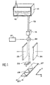
brevet et représenté figure 1, une telle imprimante
comporte un réservoir 11 contenant de l'encre
électriquement conductrice 10 qui est distribuée par un
canal de distribution 13 vers un générateur de gouttes
16. Le rôle du générateur de gouttes 16 est de former à
partir de l'encre sous pression contenue dans le canal
de distribution 13 un ensemble de gouttes
individuelles. Ces gouttes individuelles sont
électriquement chargées au moyen d'une électrode de
charge 20 alimentée par un générateur de tension 21.
Les gouttes chargées passent au travers d'un espace
compris entre deux électrodes de déviation 23, 24 et
selon leur charge sont plus ou moins déviées. Les
gouttes les moins ou non déviées sont dirigées vers un
récupérateur 22 d'encre tandis que les gouttes déviées
sont dirigées vers un substrat 27. Les gouttes
successives d'une salve atteignant le substrat 27
peuvent ainsi être déviées vers une position extrême
basse, une position extrême haute et des positions
intermédiaires successives, l'ensemble des gouttes de
la salve formant un trait vertical de hauteur ΔX
sensiblement perpendiculaire à une direction d'avancée
relative de la tête d'impression et du substrat. La
tête d'impression est formée par le générateur de
gouttes 16, l'électrode de charge 20, les électrodes de
déviation 23, 24 et le récupérateur 22. Cette tête est
en général enfermée dans un capotage non représenté. Le
mouvement de déviation imprimé aux gouttes chargées par
les électrodes de déviation 23, 24 est complété par un
mouvement selon un axe Y perpendiculaire à l'axe X,
entre la tête d'impression et le substrat. Le temps
écoulé entre la première et la dernière goutte d'une
salve est très court. Il en résulte que malgré un
mouvement continu entre la tête d'impression et le
substrat, on peut considérer que le substrat n'a pas
bougé par rapport à la tête d'impression pendant le
temps d'une salve. Les salves sont tirées à intervalles
spatiaux réguliers. Si toutes les gouttes de chaque
salve étaient dirigées vers le substrat on imprimerait
une succession de traits de hauteur ΔX. En général
seules certaines gouttes d'une salve sont dirigées vers
le substrat. Dans ces conditions, la combinaison du
mouvement relatif de la tête et du substrat, et de la
sélection des gouttes de chaque salve qui sont dirigées
vers le substrat permet d'imprimer un motif quelconque
tel que celui représenté en 28 sur la figure 1. Si le
trait que l'on trace avec les gouttes d'une salve est
dans une direction X, le mouvement relatif de la tête
et du substrat est, dans le plan du substrat dans une
direction Y perpendiculaire à X. Les gouttes non
déviées sont dirigées vers le récupérateur selon une
trajectoire Z perpendiculaire au plan x, y du substrat.
Les gouttes imprimées arrivent sur le substrat en
suivant des trajectoires légèrement déviées par rapport
à la direction Z.It is known that an ink jet under pressure
ejected from a print nozzle can be broken into a
succession of individual drops each drop being
charged individually, in a controlled manner. Sure
the path of these drops so individually
charged, electrodes of constant potential deviate
more or less the drops depending on the charge they
own. If a drop should not reach the
printing substrate, its charge is controlled in such a way
so that it is diverted to an ink collector.
The operating principle of such printers
inkjet is well known and is described for example
in patent US-A-4,160,982. As described in this
patent and shown in Figure 1, such a printer
has a
Si le mouvement relatif de la tête et du
substrat s'effectue en continu selon la dimension la
plus grande du substrat, il y aura en général plusieurs
têtes d'impression imprimant des bandes parallèles les
unes aux autres. Un exemple d'une telle utilisation est
représenté sur les figures 1 et 2 du brevet délivré à
IBM sous le numéro FR 2 198 410.If the relative movement of the head and
substrate is carried out continuously according to the dimension
larger of the substrate, there will usually be several
printheads printing parallel strips the
to each other. An example of such use is
shown in Figures 1 and 2 of the patent issued to
IBM under
Si le mouvement relatif de la tête d'impression et du substrat dans la direction Y s'effectue selon la dimension la plus petite du substrat, l'impression est réalisée bande par bande le substrat ayant un mouvement d'avance intermittent dans la direction X après chaque balayage. Le mouvement relatif de la tête d'impression et du substrat est appelé mouvement de balayage. Le mouvement de balayage se compose ainsi d'un mouvement d'aller et de retour entre un premier bord du substrat et un second bord du substrat. Le mouvement entre un bord et l'autre bord du substrat permet d'imprimer à la volée une bande de hauteur L ou assez souvent une partie de la bande de hauteur ΔX, ΔX étant le plus souvent un sous-multiple de L. L'ensemble des bandes successivement imprimées constitue ainsi le motif à imprimer sur le substrat. Après chaque impression d'une bande ou de partie de bande, le substrat est avancé de l'espace compris entre deux bandes ou partie de bande pour impression de la bande ou partie de bande suivante. L'impression peut se faire à l'aller simplement ou à l'aller et au retour du mouvement de la tête d'impression par rapport au substrat.If the relative movement of the print head and of the substrate in the Y direction is carried out according to the smallest dimension of the substrate, the impression is carried out strip by strip the substrate having a movement intermittent advance in direction X after each scanning. The relative movement of the print head and the substrate is called the sweeping motion. The sweep movement thus consists of a movement back and forth between a first edge of the substrate and a second edge of the substrate. The movement between a edge and the other edge of the substrate allows to print to the stolen a strip of height L or quite often a part of the height band ΔX, ΔX being the most often a sub-multiple of L. The set of bands successively printed thus constitutes the motif to print on the substrate. After each impression of a strip or part of the strip, the substrate is advanced the space between two strips or part of a strip for printing the strip or part of the strip next. Printing can be done on the way simply or back and forth from the movement of the print head relative to the substrate.
Lorsque le graphisme à imprimer est coloré, les nuances multiples de couleurs sont le résultat de la superposition et de la juxtaposition des impacts d'encre provenant de buses alimentées par des encres de différentes couleurs. Le système de déplacement relatif du substrat par rapport aux têtes d'impression est réalisé de façon telle qu'un point donné du substrat est présenté successivement sous les jets d'encre de chacune des couleurs. Le système d'impression présente généralement plusieurs jets de la même encre fonctionnant simultanément, soit par la juxtaposition de têtes multiples, soit par l'utilisation de têtes multijets, soit enfin par la combinaison de ces deux types de têtes afin de parvenir à des cadences d'impressions élevées. Dans ce cas, chaque jet d'encre imprime une partie limitée du substrat. Les gouttes peuvent être produites, de façon continue, comme décrit ci-dessus en liaison avec la figure 1. Elles peuvent aussi être produites "à la demande", c'est-à-dire uniquement quand elles sont nécessaires pour les besoins de l'impression. Dans ce cas, un circuit de récupération d'encre non utilisée n'est pas nécessaire. Les moyens connus de commande des différents jets seront maintenant décrits en référence à la figure 2.When the graphics to be printed are colored, the multiple shades of colors are the result of the overlay and juxtaposition of impacts ink from nozzles supplied with inks of different colours. The relative displacement system of the substrate relative to the printheads is produced in such a way that a given point on the substrate is presented successively under the ink jets of each of the colors. The printing system presents usually multiple jets of the same ink operating simultaneously, either by juxtaposition multiple heads, either by the use of heads multijets, or finally by the combination of these two types of heads in order to achieve rates high impressions. In this case, each inkjet prints a limited part of the substrate. Drops can be produced, continuously, as described above in conjunction with Figure 1. They may also be produced "on demand", that is to say only when necessary for them printing needs. In this case, a recovery of unused ink is not necessary. Known means for controlling the different jets will now be described with reference to FIG. 2.
Le motif à imprimer est défini par un fichier
numérique. Ce fichier peut être formé à l'aide d'un
scanner, d'une palette graphique de création assistée
par ordinateur (CAO), transmis au moyen d'un réseau
informatique d'échanges de données, ou, tout
simplement, lu à partir d'un périphérique de lecture de
support de stockage de données numériques (disque
optique, CD-ROM). Le fichier numérique représentant le
motif coloré à imprimer est tout d'abord scindé en
plusieurs motifs binaires (ou bitmap) pour chacune des
encres. Il convient de noter que le cas du motif
binaire est un exemple non limitatif ; dans certaines
imprimantes, le motif à imprimer est de type "contone",
c'est-à-dire que chaque position peut être imprimée par
un nombre de gouttes variable de 1 à M. Une partie du
motif binaire est extraite du fichier pour chacun des
jets correspondants à la largeur de la bande qui va
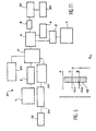
être imprimée. Sur la figure 2 où l'on s'intéresse à
l'électronique de commande d'un jet, on a représenté en
1 une mémoire de stockage du motif numérique découpée
en bande, cette mémoire de stockage contenant les
indications relatives à une couleur. Pour l'impression
de chaque bande, une mémoire intermédiaire 2 reçoit les
données nécessaires pour l'impression de la bande par
ladite couleur. Les données descriptives de la bande à
imprimer sont ensuite introduites dans un calculateur 3
des tensions de charge des différentes gouttes qui vont
former la bande relativement à cette couleur. Ces
données sont introduites dans le calculateur sous forme
d'une succession de descriptifs des trames qui ensemble
vont constituer la bande. Le calculateur 3 des tensions
de charge des gouttes se présente souvent sous la forme
d'un circuit intégré dédié. Ce calculateur 3 calcule en
temps réel la séquence de tensions à appliquer aux
électrodes de charge 20 pour imprimer une trame donnée
définie par son descriptif de trame, tel que chargé à
partir de la mémoire intermédiaire 2. Un circuit
électronique aval 4, appelé séquenceur de charge de
gouttes, assure la synchronisation des tensions de
charge avec d'une part, les instants de formation de
gouttes et, d'autre part, l'avance relative de la tête
d'impression et du substrat. L'avance du substrat par
rapport à la tête est matérialisée par une horloge de
trame 5 dont le signal est dérivé du signal d'un codeur
incrémental de position de l'unité d'impression
relativement au substrat. Le séquenceur 4 de charge des
gouttes reçoit également un signal d'une horloge de
gouttes 6. Cette horloge de gouttes est synchrone avec
le signal de commande du générateur de gouttes 16. Elle
permet de définir les instants de transitions des
différentes tensions de charges appliquées aux gouttes
pour différencier leurs trajectoires. Les données
numériques en provenance du séquenceur 4 de charge des
gouttes sont converties en valeur analogique par un
convertisseur numérique analogique 8. Ce convertisseur
délivrant un niveau de tension bas nécessite en général
la présence d'un amplificateur haute tension 21 qui va
alimenter les électrodes de charge 20. Les
illustrations de l'art antérieur données en référence
aux figures 1 et 2, sont destinées à bien faire
comprendre le domaine et l'apport de l'invention, mais
il est évident que l'art antérieur n'est pas limité aux
descriptions faites en référence à ces figures.
D'autres arrangements des électrodes et des collecteurs
de récupération des gouttes d'encre non utilisées sont
décrits dans une littérature abondante. Un arrangement
électromécanique des buses d'impression de l'électrode
de charge et des électrodes de déviation tel que décrit
dans le brevet d'invention n° FR 2 198 410 délivré à
International Business Machine Corporation (IBM) en
référence aux figures 1 à 3 de ce brevet pourrait
parfaitement être utilisé dans la présente invention.
De même, le circuit électronique de commande des
électrodes de charge pourrait être illustré par le
circuit décrit en relation avec la figure 4 de ce même
brevet. Egalement, les données à imprimées pourraient
ne pas se présenter sous forme de fichiers binaires,
mais sous formes de fichiers contenant des mots de
plusieurs bits, pour traduire le fait que chaque
position du substrat peut recevoir plusieurs gouttes
d'encre de la même couleur. On comprend que pour une
impression, en particulier en couleur, la nécessaire
superposition des gouttes provenant des différentes
buses délivrant les différentes couleurs d'encre doit
être très précise. Les défauts principaux d'impression
qui sont générés par tous les systèmes d'impression
connus, sont les défauts relatifs aux lignages dans le
sens du mouvement relatif de la tête d'impression par
rapport au substrat. Ce défaut se traduit par
l'apparition de lignes claires ou foncées lors de
l'impression par balayages successifs. Ces défauts
peuvent se trouver dans l'espace compris entre deux
bandes qui doit en principe être égal à l'intervalle
entre gouttes adjacentes d'une trame, ou à l'intérieur
d'une même bande, dans l'espace délimitant les zones
imprimées par différents jets, voire à l'intérieur de
la trame imprimée par un jet au niveau de l'espace
entre deux gouttes adjacentes de la trame. Ces défauts
de lignage peuvent provenir soit de défauts propres à
certains jets de la tête d'impression, ce sont alors
des défauts d'origine mécanique ou électrique, soit
d'erreurs de positionnement du substrat, ou bien
d'erreur de positionnement entre têtes d'impression, ou
encore entre jets d'une même tête d'impression.
Diverses solutions ont été proposées pour limiter ou
éliminer les problèmes de lignage, mais toutes se
traduisent soit par une limitation de la cadence
d'impression, dans un rapport parfois très élevé
vis-à-vis de la cadence nominale d'impression, soit par
une redondance de têtes d'impression et donc un coût
important. Des exemples de solutions connues couramment
mises en oeuvre pour limiter le lignage vont être
exposés succinctement ci-après : un premier type de
solution repose sur des réglages mécaniques fins de la
position des têtes d'impression, grâce à des tables
micrométriques. Cette solution est à la fois onéreuse,
par le nombre de tables micrométriques qui sont
nécessaires, et souvent fastidieuse, par les
tâtonnements qu'elle nécessite.The pattern to print is defined by a file
digital. This file can be formed using a
scanner, a graphic palette for assisted creation
by computer (CAD), transmitted over a network
data exchange computing, or, all
simply read from a playback device of
digital data storage medium (disc
optical, CD-ROM). The digital file representing the
colored pattern to print is first split into
several binary patterns (or bitmap) for each of
inks. It should be noted that the case of the pattern
binary is a nonlimiting example; in certain
printers, the pattern to be printed is of the "contone" type,
that is, each position can be printed by
a number of drops varying from 1 to M. Part of the
binary pattern is extracted from the file for each of
jets corresponding to the width of the strip that goes
be printed. In Figure 2 where we are interested in
the control electronics of a jet, there is shown in
1 a memory for storing the cut digital pattern
in band, this storage memory containing the
indications relating to a color. For printing
of each band, an
Un autre type de solutions courantes consiste à utiliser un taux de chevauchements très élevé entre gouttes voisines, de manière à éviter les lignages blancs. Ces lignages blancs correspondent à l'absence de couverture du substrat. Les lignages foncés sont moins visibles et on préfère avoir un défaut de lignage de lignes foncées plutôt qu'un défaut de lignage blanc. La solution consistant à augmenter le taux de chevauchements entre gouttes voisines est efficace pour compenser les défauts à l'intérieur d'une même bande et dans une certaine mesure les défauts de lignage entre bandes mais elle présente l'inconvénient de nécessiter une quantité d'encre très élevée par unité de surface du substrat et génère des difficultés de séchage ou de déformation du substrat.Another type of common solution is to use a very high overlap rate between neighboring drops, so as to avoid lineages whites. These white lines correspond to the absence substrate cover. Dark lineages are less visible and we prefer to have a lineage defect dark lines rather than a white line defect. The solution of increasing the rate of overlap between neighboring drops is effective for compensate for faults within the same band and to some extent the lineage defects between bands but it has the disadvantage of requiring a very high amount of ink per unit area of the substrate and generates difficulties in drying or deformation of the substrate.
Un troisième type de solution pour effacer les défauts de lignage sur les imprimantes fonctionnant en balayage consiste à imprimer partiellement le substrat lors de chaque balayage. En multipliant le nombre de balayages de substrat on obtient la couverture totale du substrat. Cette impression en plusieurs passages exploite diverses stratégies d'entrelacement des positions des gouttes provenant des différents jets. Un exemple d'entrelacement de lignes paires et impaires est donné dans le brevet n° US-A-4 604 631 délivré à la Société RICOH. Un avantage de cette solution souvent liée à un taux de chevauchements élevé est qu'elle autorise un temps de séchage du substrat, mais elle aboutit à la réduction de la cadence d'impression d'un facteur pouvant aller de 2 à 16.A third type of solution to erase line faults on printers operating in scanning consists in partially printing the substrate during each scan. By multiplying the number of substrate scans we get full coverage of the substrate. This impression in several passages uses various interleaving strategies positions of the drops from the different jets. A example of interleaving of even and odd lines is given in patent no. US-A-4,604,631 issued to the RICOH company. An advantage of this solution often related to a high overlap rate is that it allows a drying time for the substrate, but it results in a reduced print rate of one factor ranging from 2 to 16.
Les performances des systèmes d'impression de graphiques colorés évoluant naturellement vers des résolutions et des cadences de plus en plus élevées, il devient critique de limiter efficacement les problèmes de lignage sans faire de compromis pénalisant les cadences d'impression.The performance of printing systems colorful graphics naturally evolving towards increasingly higher resolutions and cadences it becomes critical to effectively limit problems lineage without compromising penalizing printing rates.
Le procédé selon l'invention vise à masquer certains problèmes de lignage sans conséquence sur la vitesse d'impression.The method according to the invention aims to mask some lineage issues with no impact on the printing speed.
La présente invention ne nécessite pas de taux élevé de chevauchement de gouttes. Elle permet d'atteindre des cadences d'impression élevées avec un nombre de têtes d'impression relativement réduit. Lorsqu'on minimise le chevauchement entre gouttes adjacentes il peut subsister un défaut de lignage, en particulier un défaut de lignage blanc apparaissant de façon régulière. Ce défaut est très perceptible par l'oeil lorsqu'il est régulier. De façon à diminuer la perceptibilité de cet éventuel défaut, on superpose à une tension nominale de charge des gouttes une tension additionnelle de bruit destinée à donner par rapport à la position nominale de chaque goutte une position réelle présentant un caractère de dispersion aléatoire. Grâce à cette dispersion de la position réelle de chaque goutte autour de sa position nominale, le défaut de lignage n'apparaít plus comme une ligne droite continue. Il devient donc moins perceptible à l'oeilThe present invention does not require a rate high overlapping drops. She permits achieve high print rates with a relatively few print heads. When minimizing the overlap between drops adjacent there may remain a lineage defect, in particular a white line defect appearing from on a regular basis. This defect is very noticeable by the eye when it is regular. In order to decrease the perceptibility of this possible defect, we superimpose on a nominal charge voltage of the drops a voltage additional noise intended to give compared to the nominal position of each drop a position real with a random dispersion character. Thanks to this dispersion of the actual position of each drop around its nominal position, the default no longer appears as a straight line keep on going. It therefore becomes less noticeable to the eye
L'invention est donc relative à un procédé de modification de la position d'arrivée sur un substrat de gouttes d'encre électriquement chargées de façon réglable et séquentielle par des électrodes de charge, les gouttes provenant d'une tête d'impression, les trajectoires des gouttes étant modifiables, par des électrodes de déviation, entre N positions nominales une première position X1, une dernière position XN et N-2 positions intermédiaires, les N positions définissant une trame sous forme d'un segment de droite parallèle à une direction X du substrat, procédé caractérisé en ce qu'on applique en superposition à une tension nominale appliquée aux électrodes de charge des gouttes, une tension algébrique aléatoire additionnelle masquant ainsi un éventuel défaut de lignage par dispersion de la position réelle de chaque goutte autour de sa position nominale.The invention therefore relates to a method for modifying the position of arrival on a substrate of ink drops electrically charged in an adjustable and sequential manner by charging electrodes, the drops coming from a print head, the trajectories of the drops being modifiable, by deflection electrodes, between N nominal positions a first position X 1 , a last position X N and N-2 intermediate positions, the N positions defining a frame in the form of a line segment parallel to a direction X of the substrate, a method characterized in that an additional random algebraic voltage is applied in superposition to a nominal voltage applied to the charge electrodes of drops, thus masking a possible defect in lineage by dispersion of the real position of each drop around from its nominal position.
L'amplitude moyenne de cette tension de bruit sera fonction du rang j de la goutte dans la trame. De préférence l'amplitude maximum de la tension additionnelle de bruit sera égale à une fraction inférieure à 1 de la plus petite différence entre la tension nominale Vj à appliquer à la goutte de rang j et la tension nominale VJ+1 ou Vj-1 à appliquer à l'une des deux gouttes immédiatement adjacente dans la trame imprimée à la goutte de rang j, c'est à dire les gouttes de rang j+1 et de rang j-1. The average amplitude of this noise voltage will depend on the rank j of the drop in the frame. Of preferably the maximum amplitude of the voltage additional noise will be equal to a fraction less than 1 of the smallest difference between the nominal voltage Vj to be applied to the drop of row j and the nominal voltage VJ + 1 or Vj-1 to be applied to one of the two drops immediately adjacent in the frame printed with a drop of row j, i.e. drops of row j + 1 and of row j-1.
Comme les différences de tension de charge appliquées aux gouttes imprimées adjacentes ont des valeurs assez voisines entre elles, on pourra prendre pour la valeur maximum de tension additionnelle aléatoire une fraction d'une valeur moyenne, cette valeur moyenne étant la valeur moyenne des différences de tensions nominales entre deux gouttes adjacentes imprimées dans la trame.As the differences in charging voltage applied to the adjacent printed drops have fairly close to each other, we can take for the maximum additional voltage value random a fraction of an average value, this mean value being the mean value of the differences nominal voltages between two adjacent drops printed in the frame.
De préférence l'amplitude minimum de la tension additionnelle de bruit sera égale à la valeur de l'écart de tension que l'on peut obtenir en faisant varier la valeur du bit de moindre poids d'un convertisseur analogique numérique dont la sortie alimente un amplificateur haute tension couplé aux électrodes de charge des gouttes.Preferably the minimum amplitude of the voltage additional noise will be equal to the value of the voltage difference that can be obtained by doing vary the value of the least significant bit by one analog to digital converter whose output supplies a high voltage amplifier coupled to charge electrodes for drops.
De préférence l'amplitude de la tension additionnelle de bruit correspondra à une valeur numérique aléatoire générée par un algorithme de génération de nombre pseudo aléatoire. La correspondance entre la valeur numérique aléatoire et la tension additionnelle de bruit résultera de l'application de cette valeur numérique au convertisseur numérique analogique. Le défaut régulier de lignage foncé ou blanc n'apparaítra plus ou apparaítra moins.Preferably the amplitude of the tension additional noise will correspond to a value random numeric generated by an algorithm of pseudo random number generation. The correspondence between the random numerical value and additional noise voltage will result from applying this numeric value to digital to analog converter. The regular defect of dark or white lineage will no longer appear or will appear less.
L'invention est également relative à une imprimante équipée de moyens pour réaliser le procédé selon l'invention, il s'agit d'une imprimante à jet continu dévié projetant en salve des gouttes de rang 1 à N dans la salve, les gouttes d'une salve étant dirigées ou non vers un substrat d'impression en fonction de données définissant un motif à imprimer, l'imprimante ayant au moins :
- une tête d'impression, cette tête comportant des moyens de fractionnement en gouttes d'au moins un jet d'encre et une électrode de charge des gouttes associés, des moyens de déviation d'une partie des gouttes vers le substrat d'impression,
- des moyens de contrôle de l'impression disposant d'un moyen de fixation de la charge des gouttes à diriger vers le substrat en fonction de leur rang dans la salve couplés à l'électrode de charge des gouttes,
- a print head, this head comprising means for splitting into drops of at least one ink jet and an electrode for charging the associated drops, means for deflecting part of the drops towards the printing substrate,
- printing control means having a means for fixing the charge of the drops to be directed towards the substrate as a function of their rank in the burst, coupled to the electrode for charging the drops,
Dans le mode préféré de réalisation de l'invention pour une imprimante fonctionnant en balayage, l'imprimante comporte en outre un détecteur de la position d'une marque imprimée avant chaque première trame d'une bande, ce détecteur fournissant une valeur représentative d'un écart entre les positions réelles et nominales du substrat et en ce que les moyens de contrôle de l'impression comportent en outre un calculateur d'une tension de correction de translation dynamique ϕ d'avance du substrat, ce calculateur déterminant une tension de correction de translation dynamique ϕ d'avance substrat pour chaque goutte d'une salve en fonction de son rang, cette tension de correction prenant en compte une valeur d'écart d'avance du substrat délivrée par des moyens couplés au détecteur et calculant une valeur d'écart par rapport à une position nominale, le calculateur de tension de correction de translation dynamique ϕ d'avance du substrat étant couplé aux moyens de fixation de la charge des gouttes, le moyen de fixation de la charge des gouttes prenant en compte la valeur de la tension de correction d'avance substrat générée par le calculateur de tension de correction de translation dynamique ϕ d'avance du substrat pour modifier la tension de charge de chaque goutte en fonction de la tension de correction de translation dynamique ϕ d'avance du substrat.In the preferred embodiment of the invention for a printer operating in scanning, the printer also includes a detector the position of a printed mark before each first frame of a band, this detector providing a value representative of a difference between the real and nominal positions of the substrate and that the printing control means include besides a calculator of a correction voltage of dynamic translation ϕ of the substrate in advance, this computer determining a correction voltage of dynamic translation ϕ of substrate advance for each drop of a salvo depending on its rank, this correction voltage taking into account a value deviation in advance of the substrate delivered by means coupled to the detector and calculating a deviation value with respect to a nominal position, the dynamic translation correction voltage ϕ in advance of the substrate being coupled to the means of fixing the load of the drops, the fixing means of the charge of the drops taking into account the value of the substrate advance correction voltage generated by the translation correction voltage calculator dynamic ϕ in advance of the substrate to modify the charge voltage of each drop depending on the dynamic translation correction voltage ϕ in advance of the substrate.
Une imprimante comprenant des moyens pour réaliser le procédé selon l'invention et d'autres détails du procédé selon l'invention seront maintenant décrits en regard des dessins annexés dans lesquels :
- la figure 1 déjà décrite est une représentation schématique des moyens nécessaires à la création de gouttes d'encre et à leur déviation vers un substrat ;
- la figure 2 déjà décrite comme la figure 1 dans le cadre de la description de l'art antérieur représente l'ensemble des moyens de calcul nécessaire au fonctionnement des moyens représentés sur la figure 1 ;
- la figure 3 est un schéma destiné à expliquer les modifications de l'impression obtenues par le procédé de l'invention, elle comporte trois parties A, B et C ;
- la figure 4 donne une représentation physique
agrandie de la position des gouttes :
- dans une partie A dans leurs positions nominales,
- dans une partie B dans des positions avec erreurs systématiques,
- dans une partie C dans des positions avec erreurs systématiques masquées selon l'invention ;
- la figure 5 est un schéma destiné à expliquer le mode de correction des écarts de déplacement du substrat ;
- les figures 6
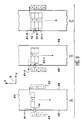
et 7 sont des schémas illustrant les éléments matériels d'une imprimante ; - la figure 8 comporte les parties A, B et C, chaque partie correspondant à une phase de la cinématique d'impression de bandes successives ;
- la figure 9 illustre un cas où un capteur de marque est mécaniquement solidaire d'une table d'impression soutenant le substrat face aux têtes d'impression ;
- la figure 10 illustre le cas où deux capteurs sont montés de part et d'autre d'un chariot portant les têtes d'impression, l'un dans une direction amont du mouvement et l'autre dans une direction aval ;
- la figure 11 est un schéma représentant les moyens de calcul d'une imprimante fonctionnant selon le procédé de l'invention ; et
- la figure 12 est une illustration du mode de détermination d'une position exacte de la marque de repérage de l'avance du substrat à partir du calcul du barycentre de l'image de la marque sur le détecteur.
- Figure 1 already described is a schematic representation of the means necessary for the creation of ink drops and their deviation to a substrate;
- Figure 2 already described as Figure 1 in the context of the description of the prior art shows all of the calculation means necessary for the operation of the means shown in Figure 1;
- FIG. 3 is a diagram intended to explain the modifications of the printing obtained by the method of the invention, it comprises three parts A, B and C;
- FIG. 4 gives an enlarged physical representation of the position of the drops:
- in part A in their nominal positions,
- in part B in positions with systematic errors,
- in part C in positions with hidden systematic errors according to the invention;
- FIG. 5 is a diagram intended to explain the mode of correction of the displacement deviations of the substrate;
- Figures 6 and 7 are diagrams illustrating the hardware of a printer;
- FIG. 8 comprises parts A, B and C, each part corresponding to a phase of the kinematics of printing successive bands;
- FIG. 9 illustrates a case where a mark sensor is mechanically secured to a printing table supporting the substrate facing the printing heads;
- FIG. 10 illustrates the case where two sensors are mounted on either side of a carriage carrying the print heads, one in an upstream direction of movement and the other in a downstream direction;
- FIG. 11 is a diagram representing the calculation means of a printer operating according to the method of the invention; and
- FIG. 12 is an illustration of the method of determining an exact position of the marking mark for the advance of the substrate from the calculation of the barycenter of the image of the mark on the detector.
La figure 3 est destinée à expliquer ce que sont les écarts provoqués par la tension algébrique additionnelle de bruit. Pour cela, on a représenté dans différentes configurations sur le plan du substrat matérialisé par des axes XY, 9 différentes positions nominales de gouttes d'une trame tracée par une salve de gouttes. Dans l'exemple représenté et pour simplifier l'explication, on a pris neuf gouttes, que l'on a représenté de façon exagérément espacée.Figure 3 is intended to explain what are the deviations caused by the algebraic tension additional noise. For this, we have represented in different configurations on the substrate plane materialized by XY axes, 9 different positions nominal drops of a frame drawn by a salvo drops. In the example shown and for simplify the explanation, we took nine drops, that one has represented it in an exaggeratedly spaced way.
En partie A de la figure 3, trois trames de
neuf gouttes numérotées de 1 à 9 sont représentées
conformément à leur position nominale par des points.
Ces trois trames font partie d'une même bande A. On
suppose que la position réelle de la goutte numéro 4
est systématiquement décalée vers la goutte numéro 5.
Cette position réelle est représentée par une croix.
L'écartement d entre les positions réelles et nominales
des gouttes de rang 4 provoque un défaut de lignage
blanc matérialisé en partie A de la figure 3 par
l'écart entre deux droites, l'une joignant les
positions nominales des gouttes, l'autre joignant les
positions réelles. Ce défaut de lignage blanc est en
général accompagné d'un défaut de lignage noir moins
visible dû au chevauchement plus accentué, dans
l'exemple ici représenté, des gouttes de rang 4 et 5
par rapport au chevauchement des autres gouttes.In part A of Figure 3, three frames of
nine drops numbered from 1 to 9 are represented
in accordance with their nominal position by dots.
These three frames are part of the same A band.
suppose the real position of the
Il convient de comprendre que le défaut réel résultant d'un écart de positionnement de deux gouttes l'une par rapport à l'autre n'est pas aussi important que ce qui a été représenté par la distance d, figure 3. Une vision plus réaliste de défaut d'écart systématique a été représentée figure 4. Cette figure comporte les parties A, B et C. En partie A, on a représenté deux successions de cinq trames comportant chacune neuf gouttes numérotées de 1 à 9. Les gouttes sont représentées par des cercles dont les surfaces se chevauchent partiellement entre trames et entre gouttes d'une même trame.It should be understood that the actual defect resulting from a positioning drop of two drops one over the other is not as important that what has been represented by the distance d, figure 3. A more realistic vision of a gap fault was shown in Figure 4. This figure contains parts A, B and C. In part A, we have depicted two successions of five frames comprising each nine drops numbered from 1 to 9. The drops are represented by circles whose surfaces are partially overlap between frames and between drops of the same frame.
L'une des successions de cinq trames représentées en partie A est obtenue au cours d'un premier balayage l'autre au cours d'un second balayage par exemple, un balayage aller et un balayage retour comme matérialisé par des flèches sur les trois parties de la figure 4. En parie A, les positions des neuf gouttes sont conformes à leurs positions nominales comme cela apparaít sur les cinq trames consécutives et sur une trame fictive sur laquelle on a porté les numéros des gouttes.One of the successions of five frames shown in part A is obtained during a first scan the other during a second scan for example, a forward scan and a return scan as materialized by arrows on the three parts of figure 4. In bet A, the positions of the nine drops conform to their nominal positions as it appears on the five consecutive frames and on a fictitious frame on which we wore the drop numbers.
En partie B, on a représenté une seule bande
également sur cinq trames consécutives et une trame
fictive portant les numéros des positions des gouttes.
En partie B on a supposé que la goutte de rang 5 était
systématiquement déplacée par rapport à sa position
nominale vers la goutte de rang 4. De même on a supposé
que la goutte de rang 6 était systématiquement déplacée
par rapport à sa position nominale vers la goutte de
rang 7. Chacune des positions réelles et nominales de
chacune de ces deux gouttes 5 et 6 est représentée par
un losange en partie B.In Part B, a single band is shown
also on five consecutive frames and one frame
fictitious bearing the numbers of the positions of the drops.
In part B it was assumed that the drop of
Dans l'exemple représenté les écarts d sont
tels que les gouttes de rang 5 et 6 ne se chevauchent
plus et sont tangentes l'une à l'autre. On a là,
l'amorce d'un défaut visible qui se traduit, comme
représenté figure B par une succession de points
blancs.In the example shown, the differences d are
such that the drops of
En partie C de la figure 4, on a représenté une succession de cinq trames pour lesquelles les gouttes 5 et 6 présentent le même défaut que celui commenté en liaison avec la partie B. En partie C, la position des gouttes de chaque trame est modifiée selon l'invention par une tension aléatoire ajoutée aux électrodes de charge. Il en résulte un bruitage de position. Ce bruitage casse la régularité de la succession de points blancs en sorte que le défaut est moins visible.In part C of Figure 4, there is shown a succession of five frames for which drops 5 and 6 have the same defect as that commented on in link with part B. In part C, the position of drops of each frame is modified according to the invention by a random voltage added to the electrodes of charge. This results in a position sound effect. This sound effects breaks the regularity of the succession of points white so that the fault is less visible.
Revenant à la figure 3, en partie B, on a représenté deux trames. Ces deux trames se situent dans l'ensemble des trames formant une bande immédiatement consécutive à la bande de trames représentées en partie A. Normalement les bandes A et B sont espacées l'une de l'autre d'une distance égale à la distance égale entre deux gouttes adjacentes d'une salve.Returning to FIG. 3, in part B, we have shown two frames. These two frames are located in all the frames forming a band immediately consecutive to the strip of frames represented in part A. Normally bands A and B are spaced one of each other by a distance equal to the equal distance between two adjacent drops of a salvo.
Si la distance entre la goutte 1 d'une trame de
la bande B et la goutte 9 d'une trame de la bande A est
par suite d'un défaut de positionnement systématique de
la goutte 1 ou de la goutte 9, trop grande ou trop
petite, comme représenté par des croix sur les deux
trames en partie B, on a également un défaut de lignage
blanc ou noir respectivement. On voit ainsi que le
défaut de lignage entre bandes consécutives ou à
l'intérieur d'une même bande peut avoir la même origine
consistant en un décalage systématique d'une goutte par
rapport à sa position nominale, que cette goutte soit
une première ou dernière goutte d'une salve ou une
goutte intermédiaire.If the distance between
Dans le cas d'un défaut de lignage entre bande consécutives, le défaut de lignage peut avoir une autre origine. Si l'avance du substrat par rapport à la tête d'impression n'est pas égale à l'avance nominale, un défaut de lignage peut apparaítre ou être augmenté par l'écart entre la position nominale du substrat et sa position réelle.In the event of a line-to-line defect consecutive, the lineage defect may have another origin. If the substrate advance in relation to the head is not equal to the nominal advance, a lineage defect may appear or be increased by the difference between the nominal position of the substrate and its actual position.
Un complément possible à la présente invention tenant compte de cette origine éventuelle d'un défaut de lignage sera maintenant expliqué en référence à la figure 5.A possible complement to the present invention taking into account this possible origin of a defect of lineage will now be explained with reference to the figure 5.
Ce complément de l'invention est relatif à un écart de position d'une bande dû à un écart dans l'avance du substrat. Cette correction concerne les imprimantes dans lesquelles le substrat est avancé pas à pas après l'impression de chaque bande. Selon cet aspect de l'invention, on va imprimer lors de l'impression d'une bande courante une première marque représentée en A sur la figure 5. Cette marque pourra être constituée d'un simple trait imprimé au moyen d'une ou plusieurs gouttes de rang consécutif. This complement of the invention relates to a band position deviation due to a deviation in advance of the substrate. This correction concerns printers in which the substrate is not advanced step by step after the printing of each strip. According to this aspect of the invention, we will print when printing a running tape a first mark represented at A in FIG. 5. This mark may consist of a single line printed using one or more drops of consecutive row.
Après avance du substrat la marque A est déplacée et occupe la position représentée en B sur la figure 5. Afin de matérialiser l'erreur d'écart εx d'avance du substrat, on a représenté également la position en C d'une marque fictive représentant la position nominale qu'aurait dû avoir la marque A en l'absence d'écart entre la position nominale et la position réelle. La marque C n'est pas présente sur le substrat de façon réelle. L'écart entre la marque fictive C et la marque en position B permet de déterminer l'écart εx entre la position nominale marquée en C et la position réelle marquée en B. Cet écart dans l'avance du substrat sera compensé selon cet aspect de l'invention par une modification de la charge des gouttes imprimées au cours de la bande suivante.After advance of the substrate the mark A is moved and occupies the position represented in B in FIG. 5. In order to materialize the error of deviation ε x in advance of the substrate, the position in C of a mark has also been represented fictitious representing the nominal position that the mark A should have had in the absence of difference between the nominal position and the actual position. Mark C is not actually present on the substrate. The difference between the fictitious mark C and the mark in position B makes it possible to determine the difference ε x between the nominal position marked in C and the real position marked in B. This difference in the advance of the substrate will be compensated according to this aspect of the invention by modifying the charge of the drops printed during the following strip.
L'impression de la bande suivante comportera comme l'impression de la bande courante, l'impression d'une marque de bande suivante imprimée en tenant compte de l'avance réelle du substrat. Il s'ensuit que les marques et les bandes seront toutes espacées entre elles de leur espacement nominal.The next tape will print like printing the current tape, printing of a mark of the following strip printed while holding account of the actual advance of the substrate. It follows that the marks and bands will all be spaced between them from their nominal spacing.
La détection de l'écart εx entre la marque B et
la position nominale C de la bande qui va être imprimée
sera effectuée au moyen d'un capteur 12, par exemple un
capteur CCD permettant de mesurer cette distance, par
exemple en comptant l'écart de numéro entre un élément
capteur 12a qui reçoit la marque lorsqu'elle est en
position nominale et un élément capteur 12b qui la
reçoit réellement. Ce capteur sera placé de préférence
face au substrat et disposé de telle sorte que son
champ de mesure permette de détecter la marque avec des
tolérances assez larges. Ce capteur sera de préférence
capteur d'une longueur d'onde lumineuse déterminée et
sera complété par un émetteur en direction du substrat
de cette longueur d'onde déterminée.The difference ε x between the mark B and the nominal position C of the strip which is going to be printed will be detected by means of a
Les figures 6 et 7 sont des schémas de principe d'imprimantes de motifs colorés, par jet d'encre faisant apparaítre quelques particularités nécessaires à l'incorporation de l'invention.Figures 6 and 7 are block diagrams inkjet printers showing some necessary features to the incorporation of the invention.
Le système représenté sur les figures 6 et 7
correspond à une architecture pour impression de
formats larges choisis uniquement à titre d'exemples
non limitatifs. L'impression est réalisée par balayages
successifs dans la direction Y. Le système met en oeuvre
de façon connue un substrat 27 à partir d'une bobine 28
dont le déroulement est assuré en amont d'une unité
d'impression 29 par une paire 36 de cylindres 37, 38
d'entraínement en contact.The system shown in Figures 6 and 7
corresponds to an architecture for printing
wide formats chosen only as examples
not limiting. Printing is done by scanning
successive in direction Y. The system implements
in a known manner a
Un premier cylindre 37 est motorisé, un
deuxième cylindre 38 assure une contre pression au
point de contact. Les deux cylindres 37, 38 pincent le
substrat et l'entraínent sans glissement. L'avance du
substrat 27 est contrôlée par un codeur, non représenté
car en lui-même connu, de positions angulaires montées
sur l'axe d'un des cylindres. Après chaque avance
intermittente du substrat, la zone à imprimer de celui-ci
est maintenue à plat sur une table d'impression 30,
située sous le chemin de balayage de l'unité
d'impression 29. Ce maintien à plat est assuré grâce à
un deuxième système d'entraínement 39 situé en aval de
l'unité d'impression. A
Ce deuxième système d'entraínement 39 maintient
une tension constante du substrat 27. Une mise en
dépression intermittente de la table d'impression est
parfois réalisée pour améliorer la planéité du substrat
27 dans la zone d'impression.This
L'unité d'impression 29 par jet d'encre est
composée de plusieurs têtes d'impression 25 comme
celles représentées par exemple figure 1, chaque tête
étant alimentée par une des encres de couleurs
primaires, à partir de réservoirs 11 grâce à un ombilic
ou canal de distribution 13.The
Les différentes têtes d'impression 25 impriment
simultanément le substrat alors qu'il est immobile.
L'impression d'une bande est assurée par un balayage
dans la direction Y de l'unité d'impression. Le
mouvement de balayage de l'unité d'impression par
rapport au substrat est assuré par une courroie 40
solidaire de l'unité d'impression et entraínée par une
poulie motorisée 41. Le guidage de l'unité d'impression
est assuré de façon connue par un axe mécanique non
représenté.The
Chaque tête d'impression imprime une bande de largeur constante L. Les têtes d'impression peuvent être décalées dans la direction X d'avance du substrat en sorte qu'une tête n'imprime pas nécessairement la même bande au même moment qu'une autre tête d'impression correspondant à une couleur d'encre différente. Après chaque balayage, le substrat est avancé d'un incrément spatial ΔX au plus égal à la largeur de bande L mais qui est plus généralement un sous-multiple de L pour une impression en plusieurs passes.Each print head prints a strip of constant width L. The print heads can be shifted in the X direction of advance of the substrate so that a head does not necessarily print the same strip at the same time as another head ink color different. After each scan, the substrate is advanced by a spatial increment ΔX at most equal to the bandwidth L but which is more generally a submultiple of L for multiple printing passes.
L'écart des têtes d'impression selon la direction Y et éventuellement selon la direction X permet d'une part, un temps de séchage suffisant entre le dépôt des différentes couleurs d'encre et permet d'autre part, d'assurer un ordre de superposition identique des couleurs mêmes lorsque l'impression est réalisée lors de l'aller et du retour de la tête d'impression.The distance between the printheads according to the direction Y and possibly along direction X on the one hand, sufficient drying time between deposition of different ink colors and allows on the other hand, to ensure an overlay order same colors same when printing is performed during the return and return of the head printing.
Par rapport au système d'impression connu tel
que représenté sur les figures 6 et 7, l'invention
selon ce mode de réalisation présente la particularité
d'être équipée d'un détecteur 12 de détection de
l'avance réelle du substrat. La position de ce
détecteur 12 par rapport au substrat et aux têtes
d'impression est commentée ci-après en liaison avec les
figures 8 à 10.Compared to the known printing system such
as shown in Figures 6 and 7, the invention
according to this embodiment has the peculiarity
to be equipped with a
La figure 8 comprend des parties A, B et C correspondant chacune à une phase de la cinématique d'impression d'un ensemble de bandes.Figure 8 includes parts A, B and C each corresponding to a phase of the kinematics printing a set of bands.
Dans le mode de positionnement décrit en
liaison avec la figure 8, le détecteur 12 est fixe, et
fixé par exemple à un dispositif de maintien de l'axe
de translation des têtes d'impression 16. Sur les
figures 8 à 10 on a représenté quatre têtes
d'impression 25, une pour chacune des couleurs, cyan
marquée C, magenta marquée M, jaune marquée Y et noire
marquée K. Le dispositif de maintien de l'axe de
translation n'a pas été représenté car sa géométrie est
spécifique à chaque imprimante. Au surplus, il s'agit
d'un exemple. L'homme du métier saura trouver ou créer
un support pour la fixation du détecteur sachant que ce
détecteur doit remplir les fonctions qui sont décrites
ci-après.In the positioning mode described in
connection with FIG. 8, the
Le détecteur doit être capable de détecter une
marque 51, imprimée par l'une des têtes d'impression 25
entre le bord gauche 52 ou droit 53 du substrat 27 et
le début ou la fin respectivement du motif imprimé.The detector must be able to detect a
mark 51, printed by one of the
Sur la partie A de la figure 8, on a représenté
une première bande marquée 1 imprimée alors que les
têtes d'impression 25 se déplacent entre un premier
bord 52, sur la figure le bord gauche, et un second
bord 53, sur la figure le bord droit du substrat, comme
indiqué par une flèche parallèle à la direction Y de
balayage et perpendiculaire à la direction X d'avance
du substrat 27.In part A of Figure 8, there is shown
a first strip marked 1 printed while the
Comme représenté sur les parties A, B et C de
la figure 8, le détecteur 12 est placé en bordure du
substrat 27, au voisinage de la tête d'impression 25
située en seconde position dans l'ensemble des têtes.
La seconde position s'entend en comptant les têtes dans
la direction Y d'avance du substrat 27. La première
tête est celle qui se trouve le plus en amont par
rapport au sens de défilement du substrat.As shown in parts A, B and C of
FIG. 8, the
Dans une direction Z perpendiculaire au plan du
substrat, le détecteur 12 est à une hauteur par rapport
au substrat inférieure à la hauteur des parties basses
de la tête d'impression de façon à leur laisser le
passage. La proximité du substrat permet une meilleure
précision de lecture. In a direction Z perpendicular to the plane of the
substrate,
L'usage des marques 51 et du détecteur 12, en
relation avec la cinématique d'impression sera
maintenant explicité.The use of marks 51 and
Avant l'impression d'une première bande marquée
1, la marque 51-1 est imprimée par la tête 25 cyan.
Cette même tête cyan imprime ensuite la bande 1 dans le
sens du balayage indiqué par une flèche dans la
direction Y. Avant le balayage, les têtes 25 se
trouvent dans la position représentée en pointillés en
partie gauche de la figure 8 partie A. En fin de
balayage, les têtes 25 se trouvent dans la position
représentée en traits pleins à droite du substrat 27.Before printing a marked
Ensuite, chronologiquement, le substrat 27 est
avancé de un pas. La marque 51-1 se trouve dans le
champ du détecteur 12. Le détecteur 12 détecte un écart
éventuel de l'avance du substrat par rapport à l'avance
nominale, et les moyens de calcul 34, 35 calculent des
corrections à apporter aux tensions de charge des
gouttes de la tête cyan et de la tête magenta, pour que
la modification de trajectoire des gouttes compense
l'écart d'avance du substrat.Then, chronologically, the
Dans le mouvement de retour des têtes, la tête
25 magenta, imprime la seconde couleur sur la bande 1
et la tête 25 cyan imprime la seconde bande puis la
marque 51-2. En fin de balayage retour, les têtes 16 se
retrouvent du côté du premier bord tel que représenté
en partie B.In the return movement of the heads, the
Le substrat est à nouveau avancé en sorte que
la marque 51-2 arrive dans le champ du détecteur 12,
comme représenté en partie C figure 8. The substrate is again advanced so that
the mark 51-2 arrives in the field of the
Le détecteur détecte un écart éventuel de la marque 51-2 par rapport à sa position nominale.The detector detects a possible deviation of the mark 51-2 from its nominal position.
Ensuite, au cours d'un balayage du premier bord
52 vers le second bord 53, la marque 51-3 et la
troisième bande sont imprimées par la tête amont cyan.
La tête 25 magenta imprime la seconde bande avec des
corrections de tension de charge des gouttes pour tenir
compte de la valeur du dernier écart εx, la tête Y jaune
imprime la première bande.Then, during a scan from the
A la fin du troisième balayage, les têtes 25 se
trouvent du côté du second bord 53. Le cycle continu.
Le substrat est avancé. Le détecteur détecte un écart
éventuel de la marque 51-3 par rapport à sa position
nominale. Une correction tenant compte de cet écart est
appliquée pour charger les gouttes de la tête noire qui
va imprimer par superposition la première bande, à la
tête Y jaune qui va imprimer la deuxième bande et aux
têtes magenta et cyan qui vont imprimer respectivement
la troisième bande et la marque 51-4 suivi de la
quatrième bande.At the end of the third scan, the
Le cycle continue ainsi modulo le nombre de têtes d'impression juxtaposé, par exemple quatre dans le cas représenté en liaison avec la figure 8.The cycle thus continues modulo the number of print heads side by side, for example four in the case shown in connection with FIG. 8.
La cinématique qui vient d'être décrite concerne une impression dans laquelle les têtes impriment dans le mouvement de balayage aller et dans le mouvement de balayage retour.The kinematics which has just been described concerns an impression in which the heads print in the sweep movement go and in the back sweep movement.
La cinématique serait la même en cas
d'impression uniquement par balayage aller, l'avance du
substrat se faisant en même temps que le mouvement de
retour des têtes vers le premier bord 52. The kinematics would be the same in case
print only by forward scan, advance of
substrate taking place at the same time as the movement of
heads return to the
On remarque que le fonctionnement qui vient d'être décrit, suppose implicitement que la somme algébrique cumulée des écarts d'avance du substrat, reste faible.We notice that the functioning which comes to be described, implicitly assumes that the sum cumulative algebraic of deviations in advance of the substrate, remains weak.
Pour pallier à des dérives importantes de l'avance du substrat, la commande moteur d'avance du substrat pourra comporter un asservissement qui tient compte des écarts d'avance du substrat. Cet asservissement connu de l'homme de l'art pourra être du type "proportionnel intégral et dérivé" c'est-à-dire qu'il tient compte des écarts réels, de leur cumul et de leur variation dans le temps afin d'éviter les dérives.To overcome significant deviations from substrate advance, motor advance control of substrate may include a servo which holds account for deviations in advance of the substrate. This enslavement known to those skilled in the art could be "proportional integral and derivative" type, that is to say that it takes into account the actual differences, their cumulation and of their variation over time in order to avoid drifts.
La lecture des marques, la détermination de l'écart d'avance du substrat et la correction des trames permet à tout instant d'assurer la bonne superposition des bandes.Reading brands, determining substrate advance deviation and correction of frames allows at all times to ensure good overlapping bands.
Selon une amélioration de logiciel, on cherche à se prémunir contre un blocage inopiné de l'avance du substrat qui ne serait pas dû à un non fonctionnement des systèmes de déroulement et de traction du substrat détectés par ailleurs.According to a software improvement, we are looking for to guard against an unexpected blocking of the advance of the substrate which is not due to non-functioning substrate unwinding and traction systems otherwise detected.
En cas de blocage du substrat, la marque
imprimée lors de l'impression d'une bande courante et
qui sert de référence de position pour l'impression de
la bande suivante, n'arrive pas dans le champ du
détecteur 12. Le détecteur 12 va donc réutiliser la
marque ayant servi pour l'impression de la bande
courante avec les mêmes corrections, en sorte que si
l'on ne détecte pas le blocage ou le quasi blocage du
substrat la bande suivante va s'imprimer en
chevauchement sur la bande précédente.If the substrate is blocked, the mark
printed when printing a current strip and
which serves as a position reference for printing
the following strip, does not arrive in the field of
Pour éviter cet éventuel chevauchement, le
motif imprimé des marques de rang pair est différent de
celui des marques de rang impair. Un autre cas où la
reconnaissance de la marque courante par rapport à la
marque suivante est intéressante est le cas où ces deux
marques seraient apparentes simultanément sur le
détecteur 12, par exemple l'une sur une partie extrême
amont du détecteur et l'autre sur une partie extrême
aval par rapport au sens de déplacement du substrat.
Cette situation peut se présenter en cas de cumul
d'écart d'avance atteignant une valeur positive ou
négative d'une demi-avance nominale. Dans ce cas, le
programme permettra de choisir la marque de référence
pour l'impression de la bande suivante.To avoid this possible overlap, the
printed pattern of even rank marks is different from
that of marks of odd rank. Another case where the
recognition of the current brand in relation to the
next mark is interesting is where these two
marks would appear simultaneously on the
Le programme en cas de détection d'un blocage ou quasi blocage pourra comprendre un déclenchement d'une autre avance substrat puis le déclenchement d'une alerte si un blocage est détecté à nouveau, ou au contraire le déclenchement immédiat d'une alarme.The program in case of blocking detection or quasi blocking may include a trigger of another substrate advance then the triggering of a alert if a blockage is detected again, or at otherwise the immediate triggering of an alarm.
Le motif des marques de bande de rang pair et impair sera une fonction du détecteur.The pattern of even rank band marks and odd will be a function of the detector.
Si par exemple, le détecteur ne comporte qu'une
barrette d'éléments détecteurs, les motifs pair et
impair se distingueront l'un de l'autre par le nombre
de lignes de l'un comparé au nombre de lignes de
l'autre, l'écart entre lignes étant tel que chaque
ligne soit détectée par un élément capteur différent.
Il pourra s'agir aussi du même nombre de lignes mais
avec des écartements différents entre lignes
correspondant à des numéros différents des éléments
capteurs détectant ces lignes. Si le capteur 12
comporte des éléments capteurs disposés de façon
matricielle, ou si le capteur 12 est, comme il sera
décrit plus loin, mobile dans la direction X du
balayage, les motifs pairs ou impairs pourront se
distinguer, en outre, par des variations dans le sens
du balayage par exemple des points pour l'un et des
traits pour l'autre ou des écarts différents du même
motif.If for example, the detector has only one
array of detector elements, even patterns and
will be distinguished from each other by the number
of lines of one compared to the number of lines of
the other, the distance between lines being such that each
line is detected by a different sensor element.
It could also be the same number of lines but
with different spacings between lines
corresponding to different numbers of the elements
sensors detecting these lines. If the
La figure 8 a été utilisée pour décrire dans le détail le principe de la mesure et du contrôle de l'avance du substrat. En pratique, le détecteur de marque du substrat doit être placé en aval de la tête d'impression qui imprime les marques, mais dans un lieu compatible avec son encombrement. Ainsi, le positionnement du capteur dans une zone balayée par les têtes d'impression comme à la figure 8 nécessiterait un ajustement mécanique très fin de telle sorte que la tête d'impression puisse passer au-dessus du capteur lors des balayages sans risque de le heurter. Par ailleurs, ce positionnement peut créer des difficultés au niveau de la répétitivité des conditions de l'éclairage de la marque au niveau du capteur, selon que la tête est située au niveau du bord droit ou du bord gauche du substrat lors de la détection/mesure de la marque. En pratique, l'imprimante comporte sous le substrat au niveau de la zone balayée par les têtes d'impression une table d'impression qui assure un bon maintien du substrat. Le capteur pourra donc être positionné de manière fixe, en aval de la dernière tête d'impression, mais dans un lieu où le substrat est solidement maintenu par la table d'impression. Ceci permet un fonctionnement adéquat sans contrainte exigeante sur l'encombrement du capteur et son éclairage.Figure 8 was used to describe in the detail the principle of measurement and control of advance of the substrate. In practice, the substrate mark should be placed downstream of the head printing that prints the marks but in a place compatible with its size. So the positioning of the sensor in an area swept by printheads as in Figure 8 would require a very fine mechanical adjustment so that the print head can pass over the sensor during sweeps without risk of hitting it. Through elsewhere, this positioning can create difficulties at the level of the repeatability of the conditions of brand lighting at the sensor, depending on the head is located at the right edge or left edge of the substrate when detecting / measuring the brand. In practice, the printer has under the substrate in the area scanned by the heads printing a printing table that ensures good maintenance of the substrate. The sensor can therefore be fixedly positioned, downstream of the last head but in a place where the substrate is securely held by the printing table. This allows proper operation without constraint demanding on the size of the sensor and its lighting.
C'est cette position qui est représentée figure
9. Le détecteur 12 est mécaniquement couplé à la table
d'impression 30 immédiatement en aval des têtes
d'impression 25.It is this position which is represented figure
9. The
Au lieu d'être imprimée par la tête amont, la marque est imprimée, dans l'exemple représenté, par la tête aval K noire.Instead of being printed by the upstream head, the mark is printed, in the example shown, by the downstream head K black.
A cette différence près la cinématique d'impression est la même que celle décrite en relation avec la figure 8.With this difference near the kinematics is the same as that described in relation with figure 8.
Lorsque l'avance du substrat est délicate, ou lorsque la table d'impression n'est pas de taille suffisante, on aura intérêt à utiliser deux capteurs, montés de part et d'autre de la tête d'impression. Chaque capteur, respectivement noté "gauche" et "droite" détectera la marque imprimée sur le bord gauche (respectivement droit) du substrat, lors de l'impression de la marque de balayage d'indice pair qui s'effectue du bord droit vers le bord gauche (respectivement impair pour le balayage du bord gauche vers le bord droit).When the advance of the substrate is delicate, or when the printing table is not large sufficient, it would be beneficial to use two sensors, mounted on either side of the print head. Each sensor, respectively marked "left" and "right" will detect the mark printed on the edge left (respectively right) of the substrate, when printing the even index scan mark which runs from the right edge to the left edge (respectively odd for scanning the left edge towards the right edge).
Ce cas est celui représenté en figure 10. Le
détecteur 12 est porté par l'ensemble mécanique mobile
comportant les têtes d'impression qui sera appelé
chariot par la suite. This case is that shown in Figure 10. The
Sur cette figure on a représenté le cas d'une imprimante imprimant en balayage aller et en balayage retour. Le chariot comporte dans ce cas deux détecteurs, un détecteur 12-1 qui se trouve en amont des têtes d'impression lors d'un balayage aller et un détecteur 12-2 qui se trouve en amont des têtes d'impression lors d'un balayage retour. A cette fin les détecteurs 12-1, 12-2 sont situés de part et d'autre des têtes d'impression 25.In this figure the case of a printer printing in scanning and scanning return. In this case, the carriage has two detectors, a 12-1 detector which is located upstream printheads during a go scan and a detector 12-2 which is located upstream of the heads when scanning back. To this end the detectors 12-1, 12-2 are located on both sides print heads 25.
Par rapport à un détecteur fixe situé à proximité de l'un des bords du substrat le fonctionnement est légèrement différent.Compared to a fixed detector located proximity to one of the edges of the substrate the operation is slightly different.
La marque 51-1 est toujours imprimée en fin de
balayage. Il en résulte que les marques de rang impair
sont toutes du côté du second bord 53 et que les
marques de rang pair sont toutes du côté du premier
bord 52.The 51-1 mark is always printed at the end of
scanning. As a result, the odd rank marks
are all on the side of the
Ainsi, par exemple la marque 51-1 imprimée à la
fin du premier balayage sur le second bord 53 du
substrat 27 est détectée par le détecteur 12-2 qui est
en amont des têtes d'impression 25 lors du balayage
retour. Les corrections de charges des gouttes sont
effectuées et la bande numéro 2 est imprimée puis la
marque 51-2 à proximité du premier bord. Après avance
du substrat 27, cette marque 51-2 est détectée par le
détecteur 12-1. L'écart constaté est utilisé pour la
correction de l'impression de la bande 3 et de la
marque 51-3 imprimée en fin de balayage. Cette solution
présente l'avantage d'un positionnement plus aisé des
détecteurs, d'une distinction de position des marques
paires et impaires. L'inconvénient est qu'il faut un
détecteur 12 supplémentaire. La commutation pour
commuter l'entrée des moyens 34, 35 sur le détecteur
12-1 ou 12-2 est nécessaire, et peut être effectuée au
niveau du logiciel par un changement de l'adresse de
lecture de l'information d'écart substrat εx.Thus, for example, the mark 51-1 printed at the end of the first scan on the
Une autre différence importante d'une imprimante selon l'invention par rapport à une imprimante connue provient des moyens de commande de la tension de l'électrode de charge des gouttes. Un dispositif selon l'art antérieur a été décrit précédemment en relation avec la figure 2.Another important difference from a printer according to the invention compared to a known printer comes from the control means of the voltage of the drop charging electrode. A device according to the prior art has been described previously in connection with FIG. 2.
La figure 11 représente des moyens de commande
31 selon l'invention. Dans ces moyens 31 de contrôle de
l'impression, les éléments ayant même fonction que ceux
représentés sur la figure 2 portent le même numéro de
référence. Par rapport aux moyens de contrôle de
l'impression 26 représentés sur la figure 2, le
dispositif selon l'invention comprend un générateur 32
de bruit aléatoire dont la sortie est appliquée au
calculateur 3' de fixation des tensions de charge des
gouttes en fonction de leur rang de façon à modifier de
façon aléatoire la charge de chaque goutte. Ce
générateur délivre une valeur numérique aléatoire selon
un algorithme de délivrance pseudo aléatoire de nombre.
L'homme du métier sait fabriquer de tels algorithmes.
De préférence, l'algorithme sera conçu pour délivrer en
moyenne pour au moins trois quarts des valeurs générées
pour les gouttes d'un nombre de trames supérieur à une
quantité prédéterminée, une valeur inférieure au tiers
de la différence entre la tension nominale à appliquer
aux électrodes de charge pour ladite goutte et la
tension nominale à appliquer aux électrodes de charge
pour l'une des deux gouttes immédiatement adjacentes de
la trame. De préférence également, le quotient du
nombre de fois où le signe de la valeur de la tension
algébrique additionnelle est positif, au nombre de
tensions additionnelles total sera en moyenne sur un
grand nombre de valeurs additionnelles égal à ½. Cela
reflète le fait que, en moyenne, une goutte de rang j
sera écartée de sa position centrale correspondant à
une tension aléatoire additionnelle nulle, avec la même
probabilité vers la goutte de rang supérieur ou vers la
goutte de rang inférieur. Pour les gouttes d'extrémité
il s'agira d'un écart vers l'extérieur ou vers la
goutte la plus proche de la trame.Figure 11 shows control means
31 according to the invention. In these
De cette façon, la position des gouttes sera légèrement bruitée. Les trois quarts des gouttes seront à une distance de leur position nominale sans variation aléatoire de tension, inférieur au 1/3 de la distance nominale séparant deux gouttes avec une probabilité égale que cette distance soit vers la goutte de rang supérieur ou inférieur. la quantité prédéterminée de trames sur laquelle sera calculée la moyenne des écarts des gouttes par rapport à la position réelle qu'elles occupent lorsqu'on leur applique la tension nominale qui correspond à leur rang pourra par exemple être égale au nombre de trames contenues dans trois bandes. Naturellement, il est possible de choisir des algorithmes de génération de façon différente ou même de disposer de plusieurs algorithmes aux choix par exemple en fonction d'une densité locale de points imprimés par la buse. In this way, the position of the drops will be slightly noisy. Three quarters of the drops will at a distance from their nominal position without variation voltage random, less than 1/3 of the distance nominal separating two drops with a probability equal that this distance is towards the drop of rank higher or lower. the predetermined amount of frames on which the average of the deviations will be calculated drops from the actual position they occupy when applied to nominal voltage which corresponds to their rank could for example be equal to the number of frames contained in three bands. Naturally, it is possible to choose generation algorithms differently or even to have several algorithms to choose from example according to a local density of points printed by the nozzle.
En raison de la dispersion des gouttes autour de la position réelle qu'elles occupent lorsqu'on leur applique la tension nominale de charge qui correspond à leur rang un éventuel défaut de lignage tel que celui matérialisé, figure 3, par les deux droites séparées de la distance d, n'apparaít plus ou apparaít moins car des gouttes vont se trouver dans l'espace entre ces deux droites, rompant la linéarité du défaut et rendant donc sa perception plus difficile.Due to the dispersion of the drops around of the actual position they occupy when they are applies the nominal charging voltage which corresponds to their rank a possible lineage defect such as that materialized, figure 3, by the two lines separated from the distance d, no longer appears or appears less because drops will be in the space between these two straight lines, breaking the linearity of the defect and rendering therefore its perception more difficult.
Dans le mode préféré de réalisation
l'imprimante comporte le détecteur 12 d'écart entre
l'avance réelle du substrat et son avance nominale. Les
moyens de contrôle 31 de l'impression comportent donc
de plus, un calculateur 34 d'écart de position du
substrat. Les éléments, détecteurs 12, calculateur 34
d'écart de position sont connectés en série l'un à
l'autre et à un calculateur 35 de tension de correction
de translation dynamique ϕ d'avance du substrat. Les
corrections de translation dynamique ϕ déterminées par
le calculateur 35 en fonction de la valeur de l'erreur
d'écart εx de la position réelle du substrat par rapport
à sa position nominale et en fonction du rang j de la
goutte, sont appliquées au calculateur 3' des tensions
de charge des gouttes. Le calcul de tension de charge
additionnelle à appliquer à chaque goutte de la salve
en fonction de son rang peut utiliser des valeurs
mémorisées de tension additionnelle à appliquer pour
corriger des écarts εx figurant dans une table d'écarts.
Ces valeurs seront interpolées en fonction de l'écart
réel. Le calcul peut aussi utiliser un algorithme
faisant intervenir outre l'écart εx, des données connues
du constructeur de l'imprimante telle que la masse
unitaire des gouttes, la valeur du champ électrique
créé par la tension des électrodes de déviation, des
lois de variation de la position des gouttes en
fonction de la tension appliquée aux électrodes de
charge 20.In the preferred embodiment, the printer comprises the
Le fonctionnement est le suivant.The operation is as follows.
Le détecteur 12 détecte l'écart entre une
marque relative à la bande courant qui va être imprimée
et la position nominale de cette bande. Cet écart est
introduit dans le calculateur 34 de calcul d'écart. ce
calculateur calcule en fonction du signal transmis par
le capteur 12, la valeur εx d'écart d'avance du substrat
27. Cet écart est introduit dans le calculateur 35 de
translation dynamique qui va calculer des corrections à
appliquer au calculateur 3' des tensions de charge des
gouttes pour corriger cette translation dynamique. Le
calculateur 3' de la tension de charge des gouttes va
calculer la somme algébrique des tensions à appliquer à
l'électrode de charge des gouttes en additionnant la
tension nominale résultant du descriptif de la trame
provenant de la mémoire 2, la valeur sortie par le
générateur de bruit aléatoire 32, et enfin la valeur de
correction résultant de la correction d'écart effectué
par le calculateur 35 de correction de translation
dynamique ϕ.The
Une autre fonction du calculateur 34 est
relative à la reconnaissance de la marque et au
traitement des informations transmises par le capteur
12 pour en déduire un écart de la marque par rapport à
sa position nominale. Il a été signalé rapidement plus
haut qu'un traitement simple pour déterminer la valeur
de l'écart d'avance du substrat consistait à compter le
nombre d'éléments de capteurs entre l'élément de
capteur correspondant à la position nominale numérotée
0 et l'élément de capteur recevant la marque. Cette
façon de faire suppose implicitement que l'épaisseur de
la marque est du même ordre de grandeur que la
résolution du capteur. Dans ces conditions, l'écart est
déterminé par le numéro de l'élément capteur détectant
la marque, si cet élément est unique. Si la détection
de la marque se trouve à cheval sur deux éléments
capteurs l'écart est calculé comme étant une fonction
du numéro de l'élément capteur le plus proche qui
perçoit la marque, augmenté d'un incrément faisant
intervenir la distance entre deux éléments capteurs et
les proportions par exemple de courant en provenance de
chacun des deux éléments capteurs concernés.Another function of the
On a représenté en figure 12, sur un exemple de
réalisation, différents cas susceptibles de se
présenter et leur mode de traitement lorsque la
résolution du capteur est plus importante que le
diamètre des gouttes. Dans l'exemple représenté figure
12, la marque est composée de plusieurs traits, trois
dans l'exemple commenté, tracés par différentes gouttes
d'une salve par exemple les gouttes correspondant aux
positions 2, 4 et 6 d'une salve de neuf gouttes.There is shown in Figure 12, on an example of
realization, different cases likely to arise
present and how they are treated when the
sensor resolution is more important than the
diameter of the drops. In the example shown figure
12, the mark is composed of several lines, three
in the commented example, traced by different drops
of a burst for example the drops corresponding to
Dans les différents cas l'écart, par rapport à
la position nominale, sera calculé par le calculateur
34, à partir du calcul de la position de la projection
du barycentre de la marque 51 sur un axe X parallèle à
l'avance du substrat.In the different cases the deviation from
the nominal position, will be calculated by the
Ce barycentre est déterminé en fonction des
éléments capteurs qui voient la marque. Si comme
représenté en figure 12 partie A, les gouttes sont
normalement positionnées, la mesure sera exacte. Si
comme représenté en partie B, les gouttes de rang 5 et
6 sont déplacées par rapport à leur position nominale,
l'erreur sera amoindrie. Il en ira de même si le
générateur de tension aléatoire 32, n'est pas inhibé au
moment de l'impression de la marque comme représenté en
partie C. Il va de soi qu'il est préférable d'inhiber
ce générateur 32 afin de minimiser l'erreur.This barycenter is determined based on
sensor elements that see the mark. If like
represented in figure 12 part A, the drops are
normally positioned, the measurement will be exact. Yes
as shown in part B, the drops of
Dans le cas de détecteurs de position mobiles comme commenté en liaison avec la figure 10, la mesure de position des marques pourra résulter d'échantillonnages effectués pendant le balayage de la tête d'impression, la précision de la mesure sera accrue, et l'influence du bruit minimisée.In the case of mobile position detectors as commented in connection with figure 10, the measurement position of brands may result of samples taken during the scanning of the print head, the measurement accuracy will be increased, and the influence of noise minimized.
Claims (7)
Applications Claiming Priority (2)
| Application Number | Priority Date | Filing Date | Title |
|---|---|---|---|
| FR9915270 | 1999-03-12 | ||
| FR9915270A FR2801834B1 (en) | 1999-12-03 | 1999-12-03 | PROCESS AND PRINTER WITH FAULT MASKING |
Publications (2)
| Publication Number | Publication Date |
|---|---|
| EP1106357A1 true EP1106357A1 (en) | 2001-06-13 |
| EP1106357B1 EP1106357B1 (en) | 2006-01-18 |
Family
ID=9552864
Family Applications (1)
| Application Number | Title | Priority Date | Filing Date |
|---|---|---|---|
| EP00403350A Expired - Lifetime EP1106357B1 (en) | 1999-12-03 | 2000-11-30 | Method and printer with fault masking |
Country Status (8)
| Country | Link |
|---|---|
| US (1) | US6485134B2 (en) |
| EP (1) | EP1106357B1 (en) |
| JP (1) | JP2001162806A (en) |
| CN (1) | CN1137817C (en) |
| DE (1) | DE60025581T2 (en) |
| ES (1) | ES2255960T3 (en) |
| FR (1) | FR2801834B1 (en) |
| IL (1) | IL139886A (en) |
Families Citing this family (12)
| Publication number | Priority date | Publication date | Assignee | Title |
|---|---|---|---|---|
| GB2379412A (en) * | 2001-09-10 | 2003-03-12 | Seiko Epson Corp | Deposition of soluble materials |
| GB0220227D0 (en) * | 2002-08-30 | 2002-10-09 | Xaar Technology Ltd | Droplet deposition apparatus |
| US7252372B2 (en) * | 2004-03-08 | 2007-08-07 | Fujifilm Corporation | Liquid ejection apparatus and ejection control method |
| JP4282520B2 (en) * | 2004-03-24 | 2009-06-24 | シャープ株式会社 | Signal processing method, signal output device, signal processing device, image processing device, and image forming device |
| JP4343867B2 (en) * | 2004-04-13 | 2009-10-14 | キヤノン株式会社 | Inkjet recording device |
| US7249829B2 (en) * | 2005-05-17 | 2007-07-31 | Eastman Kodak Company | High speed, high quality liquid pattern deposition apparatus |
| TWI346047B (en) * | 2008-05-12 | 2011-08-01 | Au Optronics Corp | Jetting method for color ink printing |
| FR2934810A1 (en) * | 2008-08-11 | 2010-02-12 | Imaje Sa | INKJET PRINTING DEVICE COMPRISING JET SPEED COMPENSATION |
| FR2934809A1 (en) * | 2008-08-11 | 2010-02-12 | Imaje Sa | INJECTOR INJECTOR INK JET PRINTING DEVICE, AIR INJECTOR, AND LARGE-WIDE PRINT HEAD |
| CN102582307B (en) * | 2011-01-10 | 2014-10-22 | 研能科技股份有限公司 | Fast wide width printing method and printing device suitable for same |
| JP6217433B2 (en) * | 2014-02-13 | 2017-10-25 | セイコーエプソン株式会社 | Image forming apparatus and dot pattern determination method |
| US10471731B2 (en) | 2015-04-23 | 2019-11-12 | Hewlett-Packard Development Company, L.P. | Printing systems |
Citations (10)
| Publication number | Priority date | Publication date | Assignee | Title |
|---|---|---|---|---|
| FR2198410A5 (en) | 1972-09-05 | 1974-03-29 | Ibm | |
| US4160982A (en) | 1978-03-24 | 1979-07-10 | A. B. Dick Company | Anti-dispersion accumulator for ink jet printing system |
| EP0036789A1 (en) * | 1980-03-26 | 1981-09-30 | Cambridge Consultants Limited | Liquid jet printing apparatus |
| US4321607A (en) * | 1980-06-17 | 1982-03-23 | International Business Machines Corporation | Scaling aerodynamic compensation in an ink jet printer |
| US4604631A (en) | 1983-12-07 | 1986-08-05 | Ricoh Company, Ltd. | Control system and method for charge control ink jet printer |
| US4847631A (en) * | 1986-07-16 | 1989-07-11 | Ricoh Company, Ltd. | Charge and deflection control type ink jet printer |
| US4849909A (en) * | 1984-11-09 | 1989-07-18 | Hitachi, Ltd. | Ink-jet recording device |
| US4897667A (en) * | 1987-12-17 | 1990-01-30 | Minolta Camera Kabushiki Kaisha | Ink jet printer |
| US5402164A (en) * | 1990-11-05 | 1995-03-28 | S.R. Technos Ltd. | Ink jet recording apparatus of the continuous jet type |
| WO1997006009A1 (en) * | 1995-08-04 | 1997-02-20 | Domino Printing Sciences Plc | Continuous ink-jet printer and method of operation |
Family Cites Families (1)
| Publication number | Priority date | Publication date | Assignee | Title |
|---|---|---|---|---|
| JPS5664878A (en) * | 1979-11-02 | 1981-06-02 | Ricoh Co Ltd | Ink jet recorder |
-
1999
- 1999-12-03 FR FR9915270A patent/FR2801834B1/en not_active Expired - Fee Related
-
2000
- 2000-11-23 IL IL13988600A patent/IL139886A/en not_active IP Right Cessation
- 2000-11-29 JP JP2000362637A patent/JP2001162806A/en not_active Withdrawn
- 2000-11-30 DE DE60025581T patent/DE60025581T2/en not_active Expired - Lifetime
- 2000-11-30 ES ES00403350T patent/ES2255960T3/en not_active Expired - Lifetime
- 2000-11-30 US US09/726,812 patent/US6485134B2/en not_active Expired - Lifetime
- 2000-11-30 EP EP00403350A patent/EP1106357B1/en not_active Expired - Lifetime
- 2000-12-02 CN CNB001373730A patent/CN1137817C/en not_active Expired - Fee Related
Patent Citations (10)
| Publication number | Priority date | Publication date | Assignee | Title |
|---|---|---|---|---|
| FR2198410A5 (en) | 1972-09-05 | 1974-03-29 | Ibm | |
| US4160982A (en) | 1978-03-24 | 1979-07-10 | A. B. Dick Company | Anti-dispersion accumulator for ink jet printing system |
| EP0036789A1 (en) * | 1980-03-26 | 1981-09-30 | Cambridge Consultants Limited | Liquid jet printing apparatus |
| US4321607A (en) * | 1980-06-17 | 1982-03-23 | International Business Machines Corporation | Scaling aerodynamic compensation in an ink jet printer |
| US4604631A (en) | 1983-12-07 | 1986-08-05 | Ricoh Company, Ltd. | Control system and method for charge control ink jet printer |
| US4849909A (en) * | 1984-11-09 | 1989-07-18 | Hitachi, Ltd. | Ink-jet recording device |
| US4847631A (en) * | 1986-07-16 | 1989-07-11 | Ricoh Company, Ltd. | Charge and deflection control type ink jet printer |
| US4897667A (en) * | 1987-12-17 | 1990-01-30 | Minolta Camera Kabushiki Kaisha | Ink jet printer |
| US5402164A (en) * | 1990-11-05 | 1995-03-28 | S.R. Technos Ltd. | Ink jet recording apparatus of the continuous jet type |
| WO1997006009A1 (en) * | 1995-08-04 | 1997-02-20 | Domino Printing Sciences Plc | Continuous ink-jet printer and method of operation |
Also Published As
| Publication number | Publication date |
|---|---|
| IL139886A0 (en) | 2002-02-10 |
| DE60025581D1 (en) | 2006-04-06 |
| CN1137817C (en) | 2004-02-11 |
| DE60025581T2 (en) | 2006-11-09 |
| ES2255960T3 (en) | 2006-07-16 |
| US6485134B2 (en) | 2002-11-26 |
| CN1300672A (en) | 2001-06-27 |
| FR2801834A1 (en) | 2001-06-08 |
| JP2001162806A (en) | 2001-06-19 |
| IL139886A (en) | 2004-05-12 |
| US20020018106A1 (en) | 2002-02-14 |
| EP1106357B1 (en) | 2006-01-18 |
| FR2801834B1 (en) | 2002-02-01 |
Similar Documents
| Publication | Publication Date | Title |
|---|---|---|
| EP1106370B1 (en) | Method and printer with substrate advance control | |
| EP1106371B1 (en) | Printer with simplified manufacturing and manufacturing method | |
| EP1106357B1 (en) | Method and printer with fault masking | |
| EP0013296B1 (en) | Multiple speed ink jet printer | |
| EP0842784B1 (en) | Continuous multi-colour inkjet press, synchronization method for such press, and printed product obtained therewith | |
| JP4273126B2 (en) | Recording apparatus and correction method | |
| CN102529409B (en) | Record of bad behavior element testing equipment and detection method and image forming apparatus | |
| US6709085B2 (en) | Scanning printing apparatus and printing method used therein | |
| US20090002424A1 (en) | Ink jet printing apparatus and method | |
| FR2611398A1 (en) | SYSTEM FOR CORRECTING AN OBLICITY BETWEEN A PRINTED IMAGE AND A PRINT WRITING HEAD | |
| FR2934810A1 (en) | INKJET PRINTING DEVICE COMPRISING JET SPEED COMPENSATION | |
| JP2011218565A (en) | Image recorder | |
| FR2604006A1 (en) | ALIGNMENT SYSTEM FOR MOBILE SUBSTRATE | |
| EP0553895B1 (en) | Printing set for franking or obliterating machine or the like | |
| JP5022977B2 (en) | Recording apparatus and recording control method | |
| EP0702334B1 (en) | System for controlling an ink jet print head in a franking machine by vernier control | |
| EP0997852A1 (en) | Device for printing postal indicia that are more readable | |
| EP0702335B1 (en) | System for controlling an ink jet print head in a franking machine by printing a stepped sequence of images | |
| JP4900442B2 (en) | Inkjet recording device | |
| CH553063A (en) | ALPHANUMERIC CHARACTER PRINTING PROCESS. | |
| FR2743527A1 (en) | Apparatus for checking operation of unit with ink reservoir in printer | |
| JP4492147B2 (en) | Ink jet recording apparatus and recording medium movement control method | |
| JP2003320661A (en) | Printer, printing method, program and computer system | |
| JP2004338199A (en) | Image processing device, image recording device, and density correction method |
Legal Events
| Date | Code | Title | Description |
|---|---|---|---|
| PUAI | Public reference made under article 153(3) epc to a published international application that has entered the european phase |
Free format text: ORIGINAL CODE: 0009012 |
|
| AK | Designated contracting states |
Kind code of ref document: A1 Designated state(s): BE DE ES FR GB IT |
|
| AX | Request for extension of the european patent |
Free format text: AL;LT;LV;MK;RO;SI |
|
| 17P | Request for examination filed |
Effective date: 20010831 |
|
| AKX | Designation fees paid |
Free format text: BE DE ES FR GB IT |
|
| GRAP | Despatch of communication of intention to grant a patent |
Free format text: ORIGINAL CODE: EPIDOSNIGR1 |
|
| GRAS | Grant fee paid |
Free format text: ORIGINAL CODE: EPIDOSNIGR3 |
|
| GRAA | (expected) grant |
Free format text: ORIGINAL CODE: 0009210 |
|
| AK | Designated contracting states |
Kind code of ref document: B1 Designated state(s): BE DE ES FR GB IT |
|
| PG25 | Lapsed in a contracting state [announced via postgrant information from national office to epo] |
Ref country code: IT Free format text: LAPSE BECAUSE OF FAILURE TO SUBMIT A TRANSLATION OF THE DESCRIPTION OR TO PAY THE FEE WITHIN THE PRESCRIBED TIME-LIMIT;WARNING: LAPSES OF ITALIAN PATENTS WITH EFFECTIVE DATE BEFORE 2007 MAY HAVE OCCURRED AT ANY TIME BEFORE 2007. THE CORRECT EFFECTIVE DATE MAY BE DIFFERENT FROM THE ONE RECORDED. Effective date: 20060118 |
|
| REG | Reference to a national code |
Ref country code: GB Ref legal event code: FG4D Free format text: NOT ENGLISH |
|
| REF | Corresponds to: |
Ref document number: 60025581 Country of ref document: DE Date of ref document: 20060406 Kind code of ref document: P |
|
| GBT | Gb: translation of ep patent filed (gb section 77(6)(a)/1977) |
Effective date: 20060321 |
|
| REG | Reference to a national code |
Ref country code: ES Ref legal event code: FG2A Ref document number: 2255960 Country of ref document: ES Kind code of ref document: T3 |
|
| PLBE | No opposition filed within time limit |
Free format text: ORIGINAL CODE: 0009261 |
|
| STAA | Information on the status of an ep patent application or granted ep patent |
Free format text: STATUS: NO OPPOSITION FILED WITHIN TIME LIMIT |
|
| PG25 | Lapsed in a contracting state [announced via postgrant information from national office to epo] |
Ref country code: BE Free format text: LAPSE BECAUSE OF NON-PAYMENT OF DUE FEES Effective date: 20061130 |
|
| 26N | No opposition filed |
Effective date: 20061019 |
|
| BERE | Be: lapsed |
Owner name: IMAJE S.A. Effective date: 20061130 |
|
| REG | Reference to a national code |
Ref country code: FR Ref legal event code: CD |
|
| PGFP | Annual fee paid to national office [announced via postgrant information from national office to epo] |
Ref country code: DE Payment date: 20101119 Year of fee payment: 11 |
|
| PGFP | Annual fee paid to national office [announced via postgrant information from national office to epo] |
Ref country code: GB Payment date: 20101118 Year of fee payment: 11 Ref country code: IT Payment date: 20101123 Year of fee payment: 11 |
|
| PGFP | Annual fee paid to national office [announced via postgrant information from national office to epo] |
Ref country code: FR Payment date: 20111130 Year of fee payment: 12 Ref country code: ES Payment date: 20111115 Year of fee payment: 12 |
|
| GBPC | Gb: european patent ceased through non-payment of renewal fee |
Effective date: 20121130 |
|
| REG | Reference to a national code |
Ref country code: FR Ref legal event code: ST Effective date: 20130731 |
|
| PG25 | Lapsed in a contracting state [announced via postgrant information from national office to epo] |
Ref country code: IT Free format text: LAPSE BECAUSE OF NON-PAYMENT OF DUE FEES Effective date: 20121130 |
|
| REG | Reference to a national code |
Ref country code: DE Ref legal event code: R119 Ref document number: 60025581 Country of ref document: DE Effective date: 20130601 |
|
| PG25 | Lapsed in a contracting state [announced via postgrant information from national office to epo] |
Ref country code: DE Free format text: LAPSE BECAUSE OF NON-PAYMENT OF DUE FEES Effective date: 20130601 |
|
| PG25 | Lapsed in a contracting state [announced via postgrant information from national office to epo] |
Ref country code: FR Free format text: LAPSE BECAUSE OF NON-PAYMENT OF DUE FEES Effective date: 20121130 Ref country code: GB Free format text: LAPSE BECAUSE OF NON-PAYMENT OF DUE FEES Effective date: 20121130 |
|
| REG | Reference to a national code |
Ref country code: ES Ref legal event code: FD2A Effective date: 20140513 |
|
| PG25 | Lapsed in a contracting state [announced via postgrant information from national office to epo] |
Ref country code: ES Free format text: LAPSE BECAUSE OF NON-PAYMENT OF DUE FEES Effective date: 20121201 |