EP1105337B1 - Elevator construction - Google Patents
Elevator construction Download PDFInfo
- Publication number
- EP1105337B1 EP1105337B1 EP00927062A EP00927062A EP1105337B1 EP 1105337 B1 EP1105337 B1 EP 1105337B1 EP 00927062 A EP00927062 A EP 00927062A EP 00927062 A EP00927062 A EP 00927062A EP 1105337 B1 EP1105337 B1 EP 1105337B1
- Authority
- EP
- European Patent Office
- Prior art keywords
- car
- above mentioned
- guide tracks
- counterweight
- hoistway
- Prior art date
- Legal status (The legal status is an assumption and is not a legal conclusion. Google has not performed a legal analysis and makes no representation as to the accuracy of the status listed.)
- Expired - Lifetime
Links
- 238000010276 construction Methods 0.000 title 1
- 239000000872 buffer Substances 0.000 claims description 4
- 238000004873 anchoring Methods 0.000 claims description 2
- 238000013016 damping Methods 0.000 claims description 2
- 238000007599 discharging Methods 0.000 claims description 2
- 230000002093 peripheral effect Effects 0.000 claims description 2
- 230000000630 rising effect Effects 0.000 claims description 2
- 230000008030 elimination Effects 0.000 description 2
- 238000003379 elimination reaction Methods 0.000 description 2
- 238000007689 inspection Methods 0.000 description 2
- 238000009434 installation Methods 0.000 description 2
- 239000002184 metal Substances 0.000 description 2
- 238000005452 bending Methods 0.000 description 1
- 238000006073 displacement reaction Methods 0.000 description 1
- 238000013213 extrapolation Methods 0.000 description 1
- 238000012423 maintenance Methods 0.000 description 1
- 230000004048 modification Effects 0.000 description 1
- 238000012986 modification Methods 0.000 description 1
- 230000000284 resting effect Effects 0.000 description 1
- 238000004513 sizing Methods 0.000 description 1
- 239000002699 waste material Substances 0.000 description 1
Images


Classifications
-
- B—PERFORMING OPERATIONS; TRANSPORTING
- B66—HOISTING; LIFTING; HAULING
- B66B—ELEVATORS; ESCALATORS OR MOVING WALKWAYS
- B66B11/00—Main component parts of lifts in, or associated with, buildings or other structures
- B66B11/0035—Arrangement of driving gear, e.g. location or support
- B66B11/0045—Arrangement of driving gear, e.g. location or support in the hoistway
-
- B—PERFORMING OPERATIONS; TRANSPORTING
- B66—HOISTING; LIFTING; HAULING
- B66B—ELEVATORS; ESCALATORS OR MOVING WALKWAYS
- B66B11/00—Main component parts of lifts in, or associated with, buildings or other structures
- B66B11/02—Cages, i.e. cars
-
- B—PERFORMING OPERATIONS; TRANSPORTING
- B66—HOISTING; LIFTING; HAULING
- B66B—ELEVATORS; ESCALATORS OR MOVING WALKWAYS
- B66B11/00—Main component parts of lifts in, or associated with, buildings or other structures
- B66B11/02—Cages, i.e. cars
- B66B11/0206—Car frames
-
- B—PERFORMING OPERATIONS; TRANSPORTING
- B66—HOISTING; LIFTING; HAULING
- B66B—ELEVATORS; ESCALATORS OR MOVING WALKWAYS
- B66B7/00—Other common features of elevators
- B66B7/02—Guideways; Guides
-
- B—PERFORMING OPERATIONS; TRANSPORTING
- B66—HOISTING; LIFTING; HAULING
- B66B—ELEVATORS; ESCALATORS OR MOVING WALKWAYS
- B66B7/00—Other common features of elevators
- B66B7/02—Guideways; Guides
- B66B7/021—Guideways; Guides with a particular position in the shaft
Definitions
- the present invention relates to a traction lift for passengers or goods and more particularly to a traction lift of the type with load car hoisting machine located beside the top of the hoistway (also termed "Traction Top Side” or TTS type).
- a traction lift for passenger or goods, with car hoisting machine located beside the hoistway is known for example from EP-A-0 686 594.
- the general purpose of the present invention is to remedy the above mentioned shortcomings by making available a traction lift with car hoisting machine located beside the upper end of the hoistway and which, in addition to obviating the prior art shortcomings, would display at least one of the following advantages:
- the traction lift according to the invention is of the type with load car hoisting machine located beside the top of the hoistway, and in which are a fixed frame supporting the hoisting machine, a counterweight and movable frame supporting the car, a traction pulley for operation of the hoisting ropes and a diverting pulley designed to locate the vertical section of the counterweight support ropes in the desired position, guide tracks for guiding the movement of the movable frame and counterweight, and brackets for fastening the tracks to the hoistway walls. It is characterized in that:
- FIGS. 1, 2 and 3 show a preferred embodiment of the traction lift in accordance with the present invention displaying a housing ("car") 1 for passengers and goods to be conveyed, fastened to a movable frame 2 (car-rack frame) running along guide tracks 31,32 arranged at its sides.
- a housing for passengers and goods to be conveyed
- a movable frame 2 car-rack frame
- the car rests on the movable frame through a base 11 and along one of its walls.
- the car can have one or more accesses 12 arranged on any of its sides except the side in contact with the frame.
- the movable frame presents a cantilever structure.
- the movable frame has as its main components two beam pairs with each pair made up of a horizontal beam 21 and a vertical beam 22 arranged according to an L position.
- the two horizontal beams act as a support for the base 11 of the car while each vertical beam accommodates at its ends two shoes 24, 25 designed to hold the movable frame on its guide tracks 31, 32.
- the two horizontal beams are connected together by two crosspieces 26 which give additional stiffness to the system.
- a third crosspiece 27 connects the upper end of the two vertical beams.
- the first two beams 26 also support a beam 29 to which are anchored (at its intersection with the vertical plane passing through the tracks 31, 32) the hauling ropes.
- the third crosspiece also acts as a support for two plates 28 with L cross section serving for the upper fastening of the car.
- the hoisting machine 5 is positioned on a fixed frame 6 supported by four pillars constituted by the movable frame guide tracks 31, 32 and by another pair of tracks 33, 34 guiding the counterweight 7. Said pillars depart from beneath said frame 6 to descend to the bottom of the hoistway (the system "pit").
- the two left-hand pillars 31, and 33 are connected together and to the wall behind through metal brackets like no. 35 of FIG 2 while the two right-hand pillars 32, 34 are connected together and to the wall behind through metal brackets like no. 36 of the same figure.
- the frame 6 is fastened to the tracks 31, 32, 33, 34 through bolts and blocks 37 welded outside the upper end of the tracks.
- buffers 38 placed between the blocks 37 and frame 6 as well as buffers 20 placed between the car base and the car-rack frame.
- This opening communicates with an adjacent compartment 8 (machine room) in which is located (at the point considered most appropriate) the electronic control system (control panel) 81 of the system.
- a stop device capable of mechanically stopping the car-rack frame by means of blocks clamping on the guide tracks.
- this stop device Operation of this stop device is caused by a speed limiting device 9 (FIG 3) having pulleys 43, 44 (with the pulley 43 having a microswitch operated when the centrifugal force generated by rotation exceeds a certain value, and with the pulley 44 having a tensioning device) whose peripheral speed is held equal to that of the car by means of a cable 45 fastened at one of its points to the car-rack frame.
- a speed limiting device 9 (FIG 3) having pulleys 43, 44 (with the pulley 43 having a microswitch operated when the centrifugal force generated by rotation exceeds a certain value, and with the pulley 44 having a tensioning device) whose peripheral speed is held equal to that of the car by means of a cable 45 fastened at one of its points to the car-rack frame.
- the car-rack frame guide tracks must therefore be sized not only in relation to the peak load to which they are subjected by the forces exerted by the car-rack frame on its tracks and the bending moment exerted by the shoes 24, 25 but also in relation to the dynamic stresses to which they would be subjected in case of parachute operation.
- the speed limiter 9 is located in the high part of the hoistway at the level of the frame 6 while, as already explained, the control panel 81 is located in the machine room. Inspection and maintenance thereof are thus easy and safe as is operation in case of emergency control to free passengers trapped in the car.
- the connection opening between the hoistway and the machine room allows easy inspection of the speed regulator.
- Rotation of the hoisting machine motor is controlled by an encoder allowing extrapolation of the position and speed of the car in the hoistway.
- a device for regulation of the level and frequency of the power supply voltage allows fine adjustment of motor rotation speed.
- a variant could concern arrangement of the machine 5 on the frame 6.
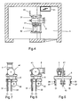
- said machine could be positioned with its motor axis arranged vertically as indicated in FIG. 7 instead of with its motor axis arranged horizontally as shown in FIG. 5. This would have the advantage of better practicability of the machine room or the possibility of further reduction of its occupied space.
Landscapes
- Engineering & Computer Science (AREA)
- Civil Engineering (AREA)
- Mechanical Engineering (AREA)
- Structural Engineering (AREA)
- Lift-Guide Devices, And Elevator Ropes And Cables (AREA)
- Types And Forms Of Lifts (AREA)
- Cage And Drive Apparatuses For Elevators (AREA)
- Load-Engaging Elements For Cranes (AREA)
Abstract
Description
- saving of useful space and making more rational use of the hoistway,
- having only one bearing wall of the hoistway, designed to bear only the forces coming from the guide track anchors,
- having much reduced machine room space not burdened by the vertical load of the car and of the counterweight, and
- allowing car access doors on three sides.
- the above mentioned movable frame presents a cantilever structure and comprises horizontal support beams for the car base and a pair of vertical beams abreast of one of the car walls,
- the vertical beams of the above mentioned pair are also abreast of the said guide tracks with which they are engaged with the possibility of vertical running,
- the above mentioned traction and diverting pulleys are both supported by the above mentioned fixed frame,
- the movable frame and counterweight guide tracks are located near a same hoistway wall, and
- the fixed frame supporting the hoisting machine discharges the overall load force on the above mentioned guide tracks which in turn discharge this overall force into the pit located at the bottom of the hoistway.
- FIG.1:
- shows a vertical cross section view of a machine room in accordance with the present invention with the car in upper limit-stop position,
- FIG.2:
- shows a horizontal cross section view of the hoistway and car of FIG 1,
- FIG.3:
- shows a perspective view of a movable car-rack frame in accordance with the present invention,
- FIG.4:
- horizontal cross section view of the machine room of FIG 1,
- FIGS. 5 and 6:
- show side and front views of the fixed frame supporting the hoisting machine of FIG 1, and
- FIG.7:
- shows a variant of FIG 5 concerning the different positioning of the hoisting machine.
- elimination of a machine room over the hoistway,
- considerably reduced space occupied by the machine room thanks to location of the hoisting machine partly in the hoistway and partly in the machine room,
- considerably reduced space occupied (in horizontal section) of the hoistway thanks to location of the supporting steel-structural work (vertical beams of the car-rack frame, counterweight, guide tracks, anchor brackets) near a same hoistway wall,
- confining the transverse forces exerted by the pulleys inside the
frame 6 because of the common location on said frame of the hoisting machine and pulleys, - discharging of all the vertical loads in the pit due to resting of the
frame 6 on the guide track pillars, resulting elimination of loads in the machine room and reduction of the bearing function of the hoistway wall behind the tracks to only the strength necessary to support the horizontal forces transmitted by the car-rack frame shoes to the tracks in the most critical situations (sudden stopping of the car with full load due to operation of the parachute), and - possibility of access to the car from three sides.
Claims (7)
- Traction lift for passenger or goods, with car hoisting machine locatable beside the top of the hoistway, comprising:characterized in that:a fixed frame (6) supporting the hoisting machine (5),a counterweight (7) and movable car-rack frame (2) for supporting the car (1),a traction pulley (41) for operation of the hauling ropes and a diverting pulley (42) designed to locate the vertical section of the counterweight support ropes in the desired position,guide tracks (31-34) guiding the movement of the car-rack frame and counterweight, andbrackets (35, 36) for fastening said tracks to the hoistway walls,the above mentioned car-rack frame presents a cantilever structure and comprises horizontal beams (21) for support of the car base (11) and a pair of vertical beams (22) abreast of one of the car walls,the vertical beams of the above mentioned pair are also abreast of the car-rack frame guide tracks (31, 32) with which they are engaged with possibility of vertical running,the above mentioned traction and diverting pulleys (41, 42) are both supported by the above mentioned fixed frame (6),the said guide tracks (31-34) of the car-rack frame and counterweight are located near a same wall of the hoistway, andthe fixed hoisting machine support frame (6) discharges the overall load force on the above mentioned guide tracks (31-34) of the car-rack frame and counterweight, which in turn is suitable for discharging said overall force inside the pit located at the bottom of the hoistway.
- Traction lift in accordance with the above claim characterized in that the guide tracks of car-rack frame and counterweight are fastened to the above mentioned same hoistway wall and that the brackets fastening the car-rack frame guide tracks to the wall are the same as those which fasten the counterweight guide tracks.
- Traction lift in accordance with claim 1 characterized in that the vertical section of the hauling ropes leading to the anchoring point with the above mentioned car-rack frame lies substantially in the plane passing through the guide tracks of the frame itself and that the vertical section of the supporting cables of the above mentioned counterweight lies substantially in the plane passing through the counterweight guide tracks.
- Traction lift in accordance with claim 1 characterized in that the hoisting machine is located partly in the hoistway and partly in a machine room abreast of the hoistway.
- Traction lift in accordance with claim 1 characterized in that the hoisting machine is located over the above mentioned fixed frame with its motor rotation axis arranged vertically.
- Traction lift in accordance with claim 1 characterized in that buffers for damping the vibration which could be transmitted from the hoisting machine to the guide tracks and the car are placed between the car base and the car-rack frame as well as between the above mentioned fixed frame and the guide tracks, i.e. between the hoisting machine and the fixed frame.
- Traction lift in accordance with the above claim characterized in that to prevent the danger of falling of the car in case of breakage of the hauling cables, in the lower part of the car-rack frame is installed a stop device capable of mechanically stopping the car-rack frame by means of blocks clamping on the guide tracks and that operation of this stop device is caused by a speed limiting device having pulleys whose peripheral speed is held equal to that of the car be means of a cable fastened at one of its points to the car-rack frame, with said limiting device causing operation of the parachute device when the above mentioned cable exceeds a predetermined peak value whether rising or falling.
Applications Claiming Priority (3)
| Application Number | Priority Date | Filing Date | Title |
|---|---|---|---|
| ITMI991324 | 1999-06-15 | ||
| IT1999MI001324A ITMI991324A1 (en) | 1999-06-15 | 1999-06-15 | LIFTING SYSTEM FOR PEOPLE AND TRACTION ROPE TYPES |
| PCT/EP2000/003752 WO2000076898A1 (en) | 1999-06-15 | 2000-04-19 | Elevator construction |
Publications (2)
| Publication Number | Publication Date |
|---|---|
| EP1105337A1 EP1105337A1 (en) | 2001-06-13 |
| EP1105337B1 true EP1105337B1 (en) | 2002-07-24 |
Family
ID=11383165
Family Applications (1)
| Application Number | Title | Priority Date | Filing Date |
|---|---|---|---|
| EP00927062A Expired - Lifetime EP1105337B1 (en) | 1999-06-15 | 2000-04-19 | Elevator construction |
Country Status (7)
| Country | Link |
|---|---|
| EP (1) | EP1105337B1 (en) |
| AT (1) | ATE221024T1 (en) |
| AU (1) | AU4557500A (en) |
| DE (1) | DE60000282D1 (en) |
| IT (1) | ITMI991324A1 (en) |
| PL (1) | PL346130A1 (en) |
| WO (1) | WO2000076898A1 (en) |
Families Citing this family (7)
| Publication number | Priority date | Publication date | Assignee | Title |
|---|---|---|---|---|
| WO2002100752A1 (en) * | 2001-06-11 | 2002-12-19 | Mac Puar, S.A. | Machine and machine bed arrangement inside the elevator pit |
| GB2395191B (en) * | 2001-11-05 | 2005-10-19 | Otis Elevator Co | Traction sheave elevators |
| ATE520617T1 (en) * | 2005-03-01 | 2011-09-15 | Ind Montanesas Electricas Mecanicas S L | MACHINE, LIFTING SYSTEM AND MACHINE ROOM-LESS ELEVATOR |
| EP3313765A1 (en) * | 2015-06-23 | 2018-05-02 | Otis Elevator Company | Increased traction of elevator system belt |
| WO2018163282A1 (en) * | 2017-03-07 | 2018-09-13 | 三菱電機株式会社 | Elevator car and elevatror car frame |
| CN115535749A (en) * | 2021-05-24 | 2022-12-30 | 湖南大举信息科技有限公司 | Multi-car intelligent parallel elevator |
| CN116553337A (en) * | 2023-06-19 | 2023-08-08 | 成都信泰科技有限公司 | A reciprocating hoist |
Family Cites Families (3)
| Publication number | Priority date | Publication date | Assignee | Title |
|---|---|---|---|---|
| EP0686594B1 (en) * | 1994-06-09 | 2000-05-17 | Aldo Loiodice | Self load bearing lift system and arrangement for mounting the main motor thereof |
| JPH1081463A (en) * | 1996-08-30 | 1998-03-31 | Otis Elevator Co | Side fork type elevator |
| DE29718047U1 (en) * | 1997-10-10 | 1999-02-04 | Vestner, Paul, 85748 Garching | Elevator system |
-
1999
- 1999-06-15 IT IT1999MI001324A patent/ITMI991324A1/en unknown
-
2000
- 2000-04-19 AU AU45575/00A patent/AU4557500A/en not_active Abandoned
- 2000-04-19 PL PL00346130A patent/PL346130A1/en not_active Application Discontinuation
- 2000-04-19 DE DE60000282T patent/DE60000282D1/en not_active Expired - Lifetime
- 2000-04-19 EP EP00927062A patent/EP1105337B1/en not_active Expired - Lifetime
- 2000-04-19 WO PCT/EP2000/003752 patent/WO2000076898A1/en not_active Ceased
- 2000-04-19 AT AT00927062T patent/ATE221024T1/en not_active IP Right Cessation
Also Published As
| Publication number | Publication date |
|---|---|
| ITMI991324A1 (en) | 2000-12-15 |
| ATE221024T1 (en) | 2002-08-15 |
| PL346130A1 (en) | 2002-01-28 |
| DE60000282D1 (en) | 2002-08-29 |
| ITMI991324A0 (en) | 1999-06-15 |
| AU4557500A (en) | 2001-01-02 |
| WO2000076898A1 (en) | 2000-12-21 |
| EP1105337A1 (en) | 2001-06-13 |
Similar Documents
| Publication | Publication Date | Title |
|---|---|---|
| KR100207905B1 (en) | Arrangement for fixing an elevator rope | |
| EP0710618B1 (en) | Traction sheave elevator | |
| CA2385569C (en) | Rope elevator | |
| AU762403B2 (en) | Machine-room-less elevator | |
| KR100326109B1 (en) | Elevator having governor | |
| KR20010040287A (en) | Traction sheave elevator | |
| KR20000023059A (en) | Traction type elevator having cable hitches securing cable ends to guide rails | |
| US20120201638A1 (en) | Method and arrangement for moving a heavy load | |
| KR20070045207A (en) | How to install an elevator and elevator | |
| KR20070037995A (en) | How to install the supporting means of the hoisting cabins and hoistways | |
| CN1446173A (en) | Elevator system using minimal building space | |
| EP1105337A1 (en) | Elevator construction | |
| JPH11139730A (en) | Elevator | |
| JPWO2003020628A1 (en) | Elevator equipment | |
| EP0687644B1 (en) | Suspension arrangement for a hydraulic elevator | |
| WO2001074704A1 (en) | Machine-room-less elevator installation structure with traction machine mounted at a rooftop | |
| JP4091326B2 (en) | Elevator equipment | |
| CN110294392B (en) | Mounting structure and mounting method of car door machine, main connecting support and auxiliary connecting support | |
| JP4195063B2 (en) | Elevator | |
| US7299896B1 (en) | Elevator system having drive motor located adjacent to hoistway door | |
| EP1329411A1 (en) | Elevator device | |
| KR20180101486A (en) | Elevator device | |
| KR200157403Y1 (en) | Balancing Device | |
| KR20100000908U (en) | Emergency stop system of elevator | |
| AU2005247035B2 (en) | Method of modernising a drive in a lift installation |
Legal Events
| Date | Code | Title | Description |
|---|---|---|---|
| PUAI | Public reference made under article 153(3) epc to a published international application that has entered the european phase |
Free format text: ORIGINAL CODE: 0009012 |
|
| 17P | Request for examination filed |
Effective date: 20000915 |
|
| AK | Designated contracting states |
Kind code of ref document: A1 Designated state(s): AT BE CH CY DE DK ES FI FR GB GR IE IT LI LU MC NL PT SE |
|
| AX | Request for extension of the european patent |
Free format text: AL;LT;LV;MK;RO;SI |
|
| GRAG | Despatch of communication of intention to grant |
Free format text: ORIGINAL CODE: EPIDOS AGRA |
|
| 17Q | First examination report despatched |
Effective date: 20010720 |
|
| GRAG | Despatch of communication of intention to grant |
Free format text: ORIGINAL CODE: EPIDOS AGRA |
|
| GRAH | Despatch of communication of intention to grant a patent |
Free format text: ORIGINAL CODE: EPIDOS IGRA |
|
| GRAH | Despatch of communication of intention to grant a patent |
Free format text: ORIGINAL CODE: EPIDOS IGRA |
|
| GRAA | (expected) grant |
Free format text: ORIGINAL CODE: 0009210 |
|
| AK | Designated contracting states |
Kind code of ref document: B1 Designated state(s): AT BE CH CY DE DK ES FI FR GB GR IE IT LI LU MC NL PT SE |
|
| AX | Request for extension of the european patent |
Free format text: AL;LT;LV;MK;RO;SI |
|
| PG25 | Lapsed in a contracting state [announced via postgrant information from national office to epo] |
Ref country code: BE Free format text: LAPSE BECAUSE OF FAILURE TO SUBMIT A TRANSLATION OF THE DESCRIPTION OR TO PAY THE FEE WITHIN THE PRESCRIBED TIME-LIMIT Effective date: 20020724 Ref country code: CH Free format text: LAPSE BECAUSE OF FAILURE TO SUBMIT A TRANSLATION OF THE DESCRIPTION OR TO PAY THE FEE WITHIN THE PRESCRIBED TIME-LIMIT Effective date: 20020724 Ref country code: FI Free format text: LAPSE BECAUSE OF FAILURE TO SUBMIT A TRANSLATION OF THE DESCRIPTION OR TO PAY THE FEE WITHIN THE PRESCRIBED TIME-LIMIT Effective date: 20020724 Ref country code: AT Free format text: LAPSE BECAUSE OF FAILURE TO SUBMIT A TRANSLATION OF THE DESCRIPTION OR TO PAY THE FEE WITHIN THE PRESCRIBED TIME-LIMIT Effective date: 20020724 Ref country code: LI Free format text: LAPSE BECAUSE OF FAILURE TO SUBMIT A TRANSLATION OF THE DESCRIPTION OR TO PAY THE FEE WITHIN THE PRESCRIBED TIME-LIMIT Effective date: 20020724 Ref country code: GR Free format text: LAPSE BECAUSE OF FAILURE TO SUBMIT A TRANSLATION OF THE DESCRIPTION OR TO PAY THE FEE WITHIN THE PRESCRIBED TIME-LIMIT Effective date: 20020724 Ref country code: NL Free format text: LAPSE BECAUSE OF FAILURE TO SUBMIT A TRANSLATION OF THE DESCRIPTION OR TO PAY THE FEE WITHIN THE PRESCRIBED TIME-LIMIT Effective date: 20020724 Ref country code: FR Free format text: LAPSE BECAUSE OF NON-PAYMENT OF DUE FEES Effective date: 20020724 |
|
| REF | Corresponds to: |
Ref document number: 221024 Country of ref document: AT Date of ref document: 20020815 Kind code of ref document: T |
|
| REG | Reference to a national code |
Ref country code: GB Ref legal event code: FG4D |
|
| REG | Reference to a national code |
Ref country code: CH Ref legal event code: EP |
|
| REG | Reference to a national code |
Ref country code: IE Ref legal event code: FG4D |
|
| REF | Corresponds to: |
Ref document number: 60000282 Country of ref document: DE Date of ref document: 20020829 |
|
| PG25 | Lapsed in a contracting state [announced via postgrant information from national office to epo] |
Ref country code: SE Free format text: LAPSE BECAUSE OF FAILURE TO SUBMIT A TRANSLATION OF THE DESCRIPTION OR TO PAY THE FEE WITHIN THE PRESCRIBED TIME-LIMIT Effective date: 20021024 Ref country code: DK Free format text: LAPSE BECAUSE OF FAILURE TO SUBMIT A TRANSLATION OF THE DESCRIPTION OR TO PAY THE FEE WITHIN THE PRESCRIBED TIME-LIMIT Effective date: 20021024 |
|
| PG25 | Lapsed in a contracting state [announced via postgrant information from national office to epo] |
Ref country code: DE Free format text: LAPSE BECAUSE OF FAILURE TO SUBMIT A TRANSLATION OF THE DESCRIPTION OR TO PAY THE FEE WITHIN THE PRESCRIBED TIME-LIMIT Effective date: 20021025 |
|
| PG25 | Lapsed in a contracting state [announced via postgrant information from national office to epo] |
Ref country code: PT Free format text: LAPSE BECAUSE OF FAILURE TO SUBMIT A TRANSLATION OF THE DESCRIPTION OR TO PAY THE FEE WITHIN THE PRESCRIBED TIME-LIMIT Effective date: 20021029 |
|
| LTIE | Lt: invalidation of european patent or patent extension |
Effective date: 20020724 |
|
| NLV1 | Nl: lapsed or annulled due to failure to fulfill the requirements of art. 29p and 29m of the patents act | ||
| PG25 | Lapsed in a contracting state [announced via postgrant information from national office to epo] |
Ref country code: ES Free format text: LAPSE BECAUSE OF FAILURE TO SUBMIT A TRANSLATION OF THE DESCRIPTION OR TO PAY THE FEE WITHIN THE PRESCRIBED TIME-LIMIT Effective date: 20030130 |
|
| REG | Reference to a national code |
Ref country code: CH Ref legal event code: PL |
|
| EN | Fr: translation not filed | ||
| PG25 | Lapsed in a contracting state [announced via postgrant information from national office to epo] |
Ref country code: CY Free format text: LAPSE BECAUSE OF FAILURE TO SUBMIT A TRANSLATION OF THE DESCRIPTION OR TO PAY THE FEE WITHIN THE PRESCRIBED TIME-LIMIT Effective date: 20030419 Ref country code: LU Free format text: LAPSE BECAUSE OF NON-PAYMENT OF DUE FEES Effective date: 20030419 |
|
| PG25 | Lapsed in a contracting state [announced via postgrant information from national office to epo] |
Ref country code: IE Free format text: LAPSE BECAUSE OF NON-PAYMENT OF DUE FEES Effective date: 20030421 |
|
| PG25 | Lapsed in a contracting state [announced via postgrant information from national office to epo] |
Ref country code: MC Free format text: LAPSE BECAUSE OF NON-PAYMENT OF DUE FEES Effective date: 20030430 |
|
| PLBE | No opposition filed within time limit |
Free format text: ORIGINAL CODE: 0009261 |
|
| STAA | Information on the status of an ep patent application or granted ep patent |
Free format text: STATUS: NO OPPOSITION FILED WITHIN TIME LIMIT |
|
| 26N | No opposition filed |
Effective date: 20030425 |
|
| REG | Reference to a national code |
Ref country code: IE Ref legal event code: MM4A |
|
| PGFP | Annual fee paid to national office [announced via postgrant information from national office to epo] |
Ref country code: GB Payment date: 20150430 Year of fee payment: 16 |
|
| PGFP | Annual fee paid to national office [announced via postgrant information from national office to epo] |
Ref country code: IT Payment date: 20150428 Year of fee payment: 16 |
|
| GBPC | Gb: european patent ceased through non-payment of renewal fee |
Effective date: 20160419 |
|
| PG25 | Lapsed in a contracting state [announced via postgrant information from national office to epo] |
Ref country code: GB Free format text: LAPSE BECAUSE OF NON-PAYMENT OF DUE FEES Effective date: 20160419 |
|
| PG25 | Lapsed in a contracting state [announced via postgrant information from national office to epo] |
Ref country code: IT Free format text: LAPSE BECAUSE OF NON-PAYMENT OF DUE FEES Effective date: 20160419 |