EP1105246B1 - Welding head - Google Patents
Welding head Download PDFInfo
- Publication number
- EP1105246B1 EP1105246B1 EP99933684A EP99933684A EP1105246B1 EP 1105246 B1 EP1105246 B1 EP 1105246B1 EP 99933684 A EP99933684 A EP 99933684A EP 99933684 A EP99933684 A EP 99933684A EP 1105246 B1 EP1105246 B1 EP 1105246B1
- Authority
- EP
- European Patent Office
- Prior art keywords
- probe
- force
- probe member
- welding apparatus
- workpiece
- Prior art date
- Legal status (The legal status is an assumption and is not a legal conclusion. Google has not performed a legal analysis and makes no representation as to the accuracy of the status listed.)
- Expired - Lifetime
Links
- 238000003466 welding Methods 0.000 title claims abstract description 71
- 239000000523 sample Substances 0.000 claims abstract description 153
- 239000012530 fluid Substances 0.000 claims description 28
- 238000000926 separation method Methods 0.000 claims description 12
- 238000000034 method Methods 0.000 claims description 9
- 238000006073 displacement reaction Methods 0.000 claims description 5
- 239000012809 cooling fluid Substances 0.000 claims description 3
- 238000001816 cooling Methods 0.000 claims 2
- 239000002826 coolant Substances 0.000 claims 1
- 238000005242 forging Methods 0.000 description 9
- 238000004886 process control Methods 0.000 description 6
- 238000005452 bending Methods 0.000 description 3
- 238000005259 measurement Methods 0.000 description 3
- 230000003287 optical effect Effects 0.000 description 3
- 238000003756 stirring Methods 0.000 description 2
- 229910000831 Steel Inorganic materials 0.000 description 1
- 238000004891 communication Methods 0.000 description 1
- 230000006870 function Effects 0.000 description 1
- 238000007789 sealing Methods 0.000 description 1
- 239000010959 steel Substances 0.000 description 1
Images



Classifications
-
- B—PERFORMING OPERATIONS; TRANSPORTING
- B23—MACHINE TOOLS; METAL-WORKING NOT OTHERWISE PROVIDED FOR
- B23K—SOLDERING OR UNSOLDERING; WELDING; CLADDING OR PLATING BY SOLDERING OR WELDING; CUTTING BY APPLYING HEAT LOCALLY, e.g. FLAME CUTTING; WORKING BY LASER BEAM
- B23K20/00—Non-electric welding by applying impact or other pressure, with or without the application of heat, e.g. cladding or plating
- B23K20/12—Non-electric welding by applying impact or other pressure, with or without the application of heat, e.g. cladding or plating the heat being generated by friction; Friction welding
- B23K20/122—Non-electric welding by applying impact or other pressure, with or without the application of heat, e.g. cladding or plating the heat being generated by friction; Friction welding using a non-consumable tool, e.g. friction stir welding
- B23K20/1245—Non-electric welding by applying impact or other pressure, with or without the application of heat, e.g. cladding or plating the heat being generated by friction; Friction welding using a non-consumable tool, e.g. friction stir welding characterised by the apparatus
- B23K20/126—Workpiece support, i.e. backing or clamping
-
- B—PERFORMING OPERATIONS; TRANSPORTING
- B23—MACHINE TOOLS; METAL-WORKING NOT OTHERWISE PROVIDED FOR
- B23K—SOLDERING OR UNSOLDERING; WELDING; CLADDING OR PLATING BY SOLDERING OR WELDING; CUTTING BY APPLYING HEAT LOCALLY, e.g. FLAME CUTTING; WORKING BY LASER BEAM
- B23K20/00—Non-electric welding by applying impact or other pressure, with or without the application of heat, e.g. cladding or plating
- B23K20/12—Non-electric welding by applying impact or other pressure, with or without the application of heat, e.g. cladding or plating the heat being generated by friction; Friction welding
- B23K20/122—Non-electric welding by applying impact or other pressure, with or without the application of heat, e.g. cladding or plating the heat being generated by friction; Friction welding using a non-consumable tool, e.g. friction stir welding
- B23K20/123—Controlling or monitoring the welding process
-
- B—PERFORMING OPERATIONS; TRANSPORTING
- B23—MACHINE TOOLS; METAL-WORKING NOT OTHERWISE PROVIDED FOR
- B23K—SOLDERING OR UNSOLDERING; WELDING; CLADDING OR PLATING BY SOLDERING OR WELDING; CUTTING BY APPLYING HEAT LOCALLY, e.g. FLAME CUTTING; WORKING BY LASER BEAM
- B23K20/00—Non-electric welding by applying impact or other pressure, with or without the application of heat, e.g. cladding or plating
- B23K20/12—Non-electric welding by applying impact or other pressure, with or without the application of heat, e.g. cladding or plating the heat being generated by friction; Friction welding
- B23K20/122—Non-electric welding by applying impact or other pressure, with or without the application of heat, e.g. cladding or plating the heat being generated by friction; Friction welding using a non-consumable tool, e.g. friction stir welding
- B23K20/1245—Non-electric welding by applying impact or other pressure, with or without the application of heat, e.g. cladding or plating the heat being generated by friction; Friction welding using a non-consumable tool, e.g. friction stir welding characterised by the apparatus
- B23K20/125—Rotary tool drive mechanism
-
- B—PERFORMING OPERATIONS; TRANSPORTING
- B23—MACHINE TOOLS; METAL-WORKING NOT OTHERWISE PROVIDED FOR
- B23K—SOLDERING OR UNSOLDERING; WELDING; CLADDING OR PLATING BY SOLDERING OR WELDING; CUTTING BY APPLYING HEAT LOCALLY, e.g. FLAME CUTTING; WORKING BY LASER BEAM
- B23K20/00—Non-electric welding by applying impact or other pressure, with or without the application of heat, e.g. cladding or plating
- B23K20/12—Non-electric welding by applying impact or other pressure, with or without the application of heat, e.g. cladding or plating the heat being generated by friction; Friction welding
- B23K20/122—Non-electric welding by applying impact or other pressure, with or without the application of heat, e.g. cladding or plating the heat being generated by friction; Friction welding using a non-consumable tool, e.g. friction stir welding
- B23K20/1245—Non-electric welding by applying impact or other pressure, with or without the application of heat, e.g. cladding or plating the heat being generated by friction; Friction welding using a non-consumable tool, e.g. friction stir welding characterised by the apparatus
- B23K20/1255—Tools therefor, e.g. characterised by the shape of the probe
-
- B—PERFORMING OPERATIONS; TRANSPORTING
- B23—MACHINE TOOLS; METAL-WORKING NOT OTHERWISE PROVIDED FOR
- B23K—SOLDERING OR UNSOLDERING; WELDING; CLADDING OR PLATING BY SOLDERING OR WELDING; CUTTING BY APPLYING HEAT LOCALLY, e.g. FLAME CUTTING; WORKING BY LASER BEAM
- B23K20/00—Non-electric welding by applying impact or other pressure, with or without the application of heat, e.g. cladding or plating
- B23K20/12—Non-electric welding by applying impact or other pressure, with or without the application of heat, e.g. cladding or plating the heat being generated by friction; Friction welding
- B23K20/122—Non-electric welding by applying impact or other pressure, with or without the application of heat, e.g. cladding or plating the heat being generated by friction; Friction welding using a non-consumable tool, e.g. friction stir welding
- B23K20/1265—Non-butt welded joints, e.g. overlap-joints, T-joints or spot welds
Definitions
- the present invention relates to a welding apparatus and a method of welding a joint between first and second workpiece sections according to the preamble of claims 1 and 17 respectively (see, for example, EP 0810055 ), for friction stir welding applications.
- Friction stir welding is a process of welding component parts together using friction heat generated at a welding joint to form a plasticized region which solidifies joining workpiece sections.
- a welding head is used to generate friction heat along a welding joint.
- the welding head includes a welding probe which is inserted into a joint between workpiece sections.
- the probe includes a pin that is inserted into the joint and a shoulder which is urged against an upper surface of the workpiece. The pin and shoulder spin to generate friction heat to form a plasticize region along the joint for welding operation.
- a workpiece is supported by a rigid table or backplate typically formed of a steel plate.
- Rigid backplate stabilizes the actuation force of the upper shoulder to maintain the integrity of the workpiece so that the workpiece does not bend or deform under the load.
- the welded portion should extend the entire thickness of the workpiece. To assure that the weld extends the entire thickness, sufficient friction heat must be generated between upper and lower surfaces of the workpiece so that the plasticized region extends between upper and lower surfaces of the workpiece.
- the thickness of a workpiece can vary along the joint. Variations in the workpiece thickness can vary pin depth or extension into the workpiece joint. If pin depth does not extend sufficient thickness, the plasticized region does not extend the entire thickness of the workpiece causing stress notches in the joint. For a smaller thickness, pin can extend too close to the backplate so that workpiece becomes joined to the backplate as a result of the welding operation.
- the present invention relates to a welding apparatus according to claim 1, with adjustable probe or pin depth to compensate for variations in workpiece thickness.
- the present invention relates to a welding method according to claim 17.
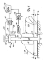
- FIG. 1 schematically illustrates an embodiment of a welding probe 50 for friction welding application.
- Welding probe 50 welds workpiece sections 52, 54 at joint 56.
- Welding probe 50 is connected to a spindle drive 58 to rotate probe 50 for welding operation.
- welding probe 50 includes an upper probe member 60, a lower probe member 62 and a probe pin 64.
- lower probe member 62 is rigidly connected to probe pin 64 and is movable therewith.
- Lower probe member 62 and probe pin 64 are slideably supported as illustrated by arrow 66 relative to upper probe member 60 for adjusting pin 64 extension relative to upper probe member 60 for use for workpieces of various thickness and for compensating for thickness variations in a workpiece as will be explained.
- upper probe member 60 includes an upper shoulder 72 and lower probe member 62 includes a lower shoulder 74.
- upper probe member 60 is supported so that shoulder 72 abuts an upper surface 76 of workpiece sections 52, 54.
- Pin 64 extends through joint 56 and shoulder 74 of lower probe member 62 abuts a lower surface 78 of the workpiece sections 52, 54.
- An upper forge actuator 80 is coupled to the upper probe member 60 and a lower forge actuator 82 is coupled to the lower probe member 62 and pin 64.
- probe 50 rotates and upper and lower forge actuators 80, 82 supply forging forces Fg 1 , Fg 2 to upper and lower probe members 60, 62 as illustrated by arrows Fg 1 , Fg 2 respectively.
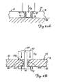
- a profile of plasticize region 92 formed by a prior art probe tapers from a thicker region 94 at an upper surface 76 of the workpiece to a thin region 96 proximate to a lower surface 78 of the workpiece. Stress notches or root openings form if the weld does not extend the entire thickness of the workpiece.
- upper and lower probe members 60, 60 form a plasticized region 98 that includes thicker regions 100, 102 at the upper and lower surfaces 76, 78 and a taper center region 104.
- Fg T
- Upper and lower forge actuators 80, 82 and spindle drive 58 are coupled to controller 106 as schematically illustrated in FIG. 1 for operation. Controller operates upper and lower forge actuators 80, 82 to maintain upper and lower probe members 60, 62 or shoulders 72, 74 in abutment with upper and lower surfaces of the workpiece to compensate for variations in workpiece thickness and profile and to provide a balanced load on opposed surfaces of the workpiece. Controller 106 can be a digital controller or an analog controller set to supply a balanced forging force for upper and lower actuators. A digital controller 106 includes a processor and memory four storing programmed instructions.
- controller operates lower forge actuator 82 to maintain appropriate spacing between upper and lower probe members 60, 62 to adjust pin 64 depth relative to workpiece thickness and variations in workpiece thickness.
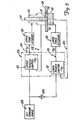
- FIG. 3 illustrates a simplified embodiment for controlling operation of upper and lower forge actuators 80, 82.
- controller 106 uses an input or command forging force 108, which is used to control upper and lower actuators 80, 82.
- Controller 106 includes upper and lower process control 110, 112 which provides operating control to upper and lower forge actuators 80, 82 as illustrated by lines 114, 116 based upon input parameters 108, 109 and control feedback 118, 120.
- feedback 118, 120 includes force feedback as will be explained to maintain a balanced load to the workpiece to limit deformation or bending of the workpiece.
- welding probe provides a plasticized profile having thicker regions relative to upper and lower surfaces 76, 78 of the workpiece to provide a relatively rigid weld joint across the thickness of the workpiece joint, while rigidly supporting the workpiece to limit bending and distortion.
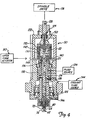
- FIG. 4 is a detailed cross-sectional view of an embodiment of a welding probe 50 including actuatable upper and lower probe members 60, 62.
- probe 50 includes an outer housing 122 and an inner housing 124 rotationally connected to outer housing by bearings 125.
- Upper probe member 60 is formed by inner housing 124.
- Pin 64 is slidably supported in housing 124 via rod 126.
- Probe member 62 is connected to pin 64 to slidably support lower shoulder 74 relative to upper shoulder 72 formed by housing 124.
- Spindle shaft 128 is coupled to housing 124 to rotate housing 124 (upper probe member 60, lower probe member 62 and pin 64) by operation of spindle drive 58 for welding operation.
- spindle drive 58 includes an inline torque transducer for spindle control.
- Spindle control includes simultaneous torque and RPM (revolutions per minute) control.
- upper forge actuator 80 is connected to outer housing 122 to position and actuator upper probe member 60 as will be explained.
- lower forge actuator 82 is a fluid actuator supported in inner housing 124 and coupled to rod 126 connected to lower probe member 62 and pin 64.
- Fluid actuator includes an actuation chamber 130 and piston 132.
- Rod 126 is connected to piston 132 operable in chamber 130.
- Actuator fluid is delivered to chamber 130 from fluid source 134 for bi-directional movement as illustrated by arrow 136.
- Fluid is delivered from fluid source 134 to rotating housing 124 by fluid commutator or slip rings 138.
- Fluid is delivered through channels 140, 142 for bi-directional actuation as illustrated by arrow 136.
- fluid source 134 is a hydraulic fluid although other fluids can be used.
- cooling fluid is supplied from a cooling fluid source 144 to channels 146 in the probe through fluid commutator 138 for temperature control during welding operation.
- Housing 122 includes upper and lower portions separated by a sealing ring 148 for operating fluid containment.
- a displacement sensor 150 (for example, a linear voltage displacement transducer "LVDT") is coupled to rod 126 for position feedback control for pin 64 extension and separation distance between upper and lower probe members 60, 62 as will be explained.
- probe housing 122 is supported for movement along a probe track 152 supported by a welding fixture 154.
- Fixture includes a base 156, and posts 160, 162 which extend from base 156 to support probe track 150 above a workpiece table or backplate 164.
- Probe track 152 is movably coupled to tracks 166, 168 along posts 160, 162 to raise and lower probe 50 as illustrated by arrow 170 for welding operation.
- Table 164 includes a groove 172 or alternately two separately spaced table sections can be used to support the workpiece. Workpiece joint is aligned with groove 172 or separation for placement of the lower probe member 62 underneath the workpiece supported by table 164.
- probe track 152 supports probe 50 for movement along a welding joint of a workpiece supported by table 164 as illustrated by arrow 174.
- Fluid actuators 176, 178 are coupled to probe track 152 to raise and lower track 152 and probe 50 as illustrated by arrow 170. Actuators 176, 178 position probe 50 relative to workpiece and supply forging force to upper probe member 60 through housing 122. Although a particular fixture is shown, application is not limited to the particular fixture.
- table 164 can be movably supported relative to base 180 as illustrated by arrows 180 for probe placement along a welding joint. Bi-directional placement of the probe as illustrated by arrows 180 facilitates complex welding operation along a curved joint in addition to straight line welding along a straight joint. Operation of the actuators 176, 178 can be independently controlled to vary rake angle 184 of the probe for contour welding operations, as will be explained.
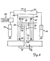
- force feedback 118 for upper probe member 60 is measured by force transducer 188 connected in series with force actuator 80 (fluid actuators 176, 178) and upper probe member 60.
- Force feedback 120 for lower probe member 62 is measured by a pressure sensor assembly for measuring pressure differential between chamber portions 190, 192 of fluid actuator 82.
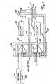
- FIG. 7 illustrates a control schematic for force and position control.
- upper and lower process control 110, 112 receive and process force 108, 109 and position 194, 196 input or command and force 118, 120 and position feedback 198, 200.
- Upper and lower process control 110, 112 includes mode switching for switching between force and position control. Mode switching includes a mode controller 202 or operating actuator 80, 82 between force and position control to maintain force and position parameter within command parameters or limits.
- Mode controller 202 switches mode control between force and position control based upon the force and position error between the program commands 108, 109, 194, 196 and feedback 118, 120, 198, 200.
- mode controller 202 provides force control to maintain force feedback relative to command parameters and switches to position if force feedback 118, 120 is within command parameters 108, 109 and provides position control to maintain position feedback within command parameter and switches to force control when position feedback 198, 200 is within command parameters.
- a proportional integrated controller (DID) provides force and position control and bumpless mode switching between force and position control.
- position feedback 198 can be used to maintain minimum separation ⁇ z between upper and lower probe members 60, 62 based upon workpiece thickness ⁇ t.
- ⁇ z can be controlled based upon preprogrammed command parameters based upon the profile of the workpiece.
- upper and lower process control 110, 112 adjust the position of upper and lower probe members 60, 62 to adjust ⁇ z (separation between upper and lower probe members 60, 62) to correspond to workpiece thickness or minimum separation command parameter.
- the position of lower probe is fixed relative to a workpiece supported by table 164.
- actuator 82 adjusts the position of upper probe member 62 for ⁇ z, and the position of the probe member 60 is also adjusted the same increment as lower probe member 62 by actuator 80 to compensate for the adjustment of lower probe member 62 to maintain the elevation of lower probe member 62 aligned with table 164.
- Position feedback can be used to compensate for profile or dimension changes in the workpiece based upon position commands.
- upper and lower probe members 60, 62 can be adjusted relative to workpiece profile data 204.
- Workpiece profile data ⁇ z 204 can be measured or downloaded off-line or during the welding process by various sensors such as optical sensors to provide position commands 194 for operation.
- the thickness of the workpiece may fluctuate or the thickness may increase ⁇ t.
- position feedback 198, 200 from upper and lower probe members 60, 62, as illustrated in FIG. 7 , and position commands can be used by controllers for placement of upper and lower probe members in abutment with upper and lower workpiece surfaces 76, 78.
- z u , z 1 and ⁇ z can be used for placement of upper and lower probe members 60, 62 based upon position feedback z u , ⁇ z and position commands for z u , ⁇ z where:
- Position commands for z u, z 1 , and ⁇ z can be derived from workpiece image or profile data which is uploaded to controller memory for execution or can be derived during the welding process via various sensors such as laser or optical sensors.
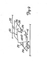
- head is flexibly supported to flexibly couple the head (upper and lower probe members) to follow the contour of the workpiece for adapting head 50 for welding complex shapes and forms.
- head 50 is flexibly supported to pitch and roll relative to an x axis by first and second frame members 210, 212 for sloped or contour welding of surface 208.
- Head 50 is pivotally connected first frame member at trunions 214 to roll relative to the x-axis as illustrated by arrow 216.
- Frame member 210 is pivotally connected to frame member 212 to support the head 50 to pitch as illustrated by arrow 218.
- pitch and roll actuators 220, 222 adjust the position of the head 50 so that the surface of the head 50 (for example, upper and lower shoulders 72, 74) are normal to the surface of the workpiece for contour welding via operation by controller 106 based upon programmed data or profile measurements received during the welding operation via optical or laser sensors.
- probe members have been described relative to an upper and lower orientation, it should be understood, that probe members are not restricted to an upper and lower orientation and the upper and lower probe members can be oriented in any opposed relation.
Landscapes
- Engineering & Computer Science (AREA)
- Mechanical Engineering (AREA)
- Pressure Welding/Diffusion-Bonding (AREA)
- Arc Welding In General (AREA)
- Resistance Welding (AREA)
- Lining Or Joining Of Plastics Or The Like (AREA)
Abstract
Description
- The present invention relates to a welding apparatus and a method of welding a joint between first and second workpiece sections according to the preamble of claims 1 and 17 respectively (see, for example,
EP 0810055 ), for friction stir welding applications. - Friction stir welding is a process of welding component parts together using friction heat generated at a welding joint to form a plasticized region which solidifies joining workpiece sections. A welding head is used to generate friction heat along a welding joint. The welding head includes a welding probe which is inserted into a joint between workpiece sections. The probe includes a pin that is inserted into the joint and a shoulder which is urged against an upper surface of the workpiece. The pin and shoulder spin to generate friction heat to form a plasticize region along the joint for welding operation.
- For welding operation, a workpiece is supported by a rigid table or backplate typically formed of a steel plate. Rigid backplate stabilizes the actuation force of the upper shoulder to maintain the integrity of the workpiece so that the workpiece does not bend or deform under the load. To maximize strength of the joint between workpiece sections, the welded portion should extend the entire thickness of the workpiece. To assure that the weld extends the entire thickness, sufficient friction heat must be generated between upper and lower surfaces of the workpiece so that the plasticized region extends between upper and lower surfaces of the workpiece.
- Typically, the thickness of a workpiece can vary along the joint. Variations in the workpiece thickness can vary pin depth or extension into the workpiece joint. If pin depth does not extend sufficient thickness, the plasticized region does not extend the entire thickness of the workpiece causing stress notches in the joint. For a smaller thickness, pin can extend too close to the backplate so that workpiece becomes joined to the backplate as a result of the welding operation. These and other problems are addressed by the present invention:
- The present invention relates to a welding apparatus according to claim 1, with adjustable probe or pin depth to compensate for variations in workpiece thickness. The present invention relates to a welding method according to claim 17.
-
-
FIG. 1 is a schematic illustration of an embodiment of a welding head of the present invention. -
FIG. 2A is an illustration of a plasticized region for a prior art probe including an upper shoulder and fixed pin. -
FIG. 2B is an illustration of a plasticized region for a probe including upper and lower probe members. -
FIG. 3 is a schematic control feedback for forging force Fg1 on upper probe member and forging force Fg2 on lower probe member. -
FIG. 4 is a cross sectional illustration of a welding head of the present invention. -
FIG. 5 is a perspective illustration of a fixture supporting a welding head of the present invention. -
FIG. 6 is a schematic illustration for force feedback Fg1 and F92 of upper and lower probe members. -
FIG. 7 is a schematic illustration of force and position control feedback for upper and lower probe members. -
FIG. 8 is a detailed illustration of an operation control embodiment for upper and lower probe members. -
FIG. 9 is a schematic illustration of a flexible mounting assembly for a welding head to follow the contour of shaped forms or components. -
FIG. 10 is a perspective illustration of a flexible mounting fixture supporting a welding head. -
FIG. 1 schematically illustrates an embodiment of awelding probe 50 for friction welding application.Welding probe 50welds workpiece sections joint 56.Welding probe 50 is connected to aspindle drive 58 to rotateprobe 50 for welding operation. As shownwelding probe 50 includes anupper probe member 60, alower probe member 62 and aprobe pin 64. As shown,lower probe member 62 is rigidly connected toprobe pin 64 and is movable therewith.Lower probe member 62 andprobe pin 64 are slideably supported as illustrated byarrow 66 relative toupper probe member 60 for adjustingpin 64 extension relative toupper probe member 60 for use for workpieces of various thickness and for compensating for thickness variations in a workpiece as will be explained. - As shown,
upper probe member 60 includes anupper shoulder 72 andlower probe member 62 includes alower shoulder 74. For operation,upper probe member 60 is supported so thatshoulder 72 abuts anupper surface 76 ofworkpiece sections Pin 64 extends throughjoint 56 andshoulder 74 oflower probe member 62 abuts alower surface 78 of theworkpiece sections - An
upper forge actuator 80 is coupled to theupper probe member 60 and alower forge actuator 82 is coupled to thelower probe member 62 andpin 64. Forwelding operation probe 50 rotates and upper andlower forge actuators lower probe members - Rotation of
pin 64 and upper andlower probe members lower surfaces FIG. 2A , a profile ofplasticize region 92 formed by a prior art probe tapers from athicker region 94 at anupper surface 76 of the workpiece to athin region 96 proximate to alower surface 78 of the workpiece. Stress notches or root openings form if the weld does not extend the entire thickness of the workpiece. - In contrast, as illustrated in
FIG. 2B , upper andlower probe members plasticized region 98 that includesthicker regions lower surfaces taper center region 104. The friction heat generated on the workpiece to form theplasticized region 98 is a function of the total forging force of the upper and lower probe members or FgT = |Fg1| +|Fg2|. Thus friction heat generated by the probe is increased by thelower probe member 62 operating in cooperation with theupper probe member 60. - Upper and
lower forge actuators spindle drive 58 are coupled tocontroller 106 as schematically illustrated inFIG. 1 for operation. Controller operates upper andlower forge actuators lower probe members shoulders Controller 106 can be a digital controller or an analog controller set to supply a balanced forging force for upper and lower actuators. Adigital controller 106 includes a processor and memory four storing programmed instructions. - In particular, controller operates
lower forge actuator 82 to maintain appropriate spacing between upper andlower probe members pin 64 depth relative to workpiece thickness and variations in workpiece thickness. Controller is programmed or set to supply balanced forging force Fg1 = Fg2 to the upper andlower probe members FIG. 3 illustrates a simplified embodiment for controlling operation of upper andlower forge actuators FIG. 3 ,controller 106 uses an input orcommand forging force 108, which is used to control upper andlower actuators FIG.3 ,input forging force 108 = Fg1 and Fg2 is the inverse as illustrated byblock 109. In an alternative embodiment,input force 108 = Fgt and Fg1 = Fgt/2 and Fg2 = - Fgt/2.Controller 106 includes upper andlower process control lower forge actuators lines input parameters control feedback feedback lower probe members biases members proper pin 64 depth based upon workpiece thickness and variations in workpiece thickness. Thus, as described, welding probe provides a plasticized profile having thicker regions relative to upper andlower surfaces -
FIG. 4 is a detailed cross-sectional view of an embodiment of awelding probe 50 including actuatable upper andlower probe members probe 50 includes anouter housing 122 and aninner housing 124 rotationally connected to outer housing bybearings 125.Upper probe member 60 is formed byinner housing 124.Pin 64 is slidably supported inhousing 124 viarod 126.Probe member 62 is connected to pin 64 to slidably supportlower shoulder 74 relative toupper shoulder 72 formed byhousing 124.Spindle shaft 128 is coupled tohousing 124 to rotate housing 124 (upper probe member 60,lower probe member 62 and pin 64) by operation of spindle drive 58 for welding operation. In one embodiment, spindle drive 58 includes an inline torque transducer for spindle control. Spindle control includes simultaneous torque and RPM (revolutions per minute) control. - As shown schematically,
upper forge actuator 80 is connected toouter housing 122 to position and actuatorupper probe member 60 as will be explained. In the embodiment shown,lower forge actuator 82 is a fluid actuator supported ininner housing 124 and coupled torod 126 connected tolower probe member 62 andpin 64. Fluid actuator includes anactuation chamber 130 andpiston 132.Rod 126 is connected topiston 132 operable inchamber 130. Actuator fluid is delivered tochamber 130 fromfluid source 134 for bi-directional movement as illustrated byarrow 136. Fluid is delivered fromfluid source 134 torotating housing 124 by fluid commutator or slip rings 138. Fluid is delivered throughchannels arrow 136. Preferably,fluid source 134 is a hydraulic fluid although other fluids can be used. - Although a fluid actuator is shown, application is not limited to a fluid actuator, and alternate actuators can be used, such as an electrical or mechanical actuator, with a fluid or electrical actuator interface, for communication between the rotating probe and stationary housing for actuation. In the embodiment shown, cooling fluid is supplied from a cooling
fluid source 144 tochannels 146 in the probe throughfluid commutator 138 for temperature control during welding operation.Housing 122 includes upper and lower portions separated by a sealingring 148 for operating fluid containment. - As previously described
force feedback lower probe members pin 64 to maintain a balance Fg1 and Fg2 on the workpiece as illustrated schematically inFIG. 1 . Additionally, in the embodiment illustrated inFIG. 4 , a displacement sensor 150 (for example, a linear voltage displacement transducer "LVDT") is coupled torod 126 for position feedback control forpin 64 extension and separation distance between upper andlower probe members - As shown in
FIG. 5 , for welding operation, probehousing 122 is supported for movement along aprobe track 152 supported by awelding fixture 154. Fixture includes abase 156, andposts base 156 to supportprobe track 150 above a workpiece table orbackplate 164.Probe track 152 is movably coupled totracks posts lower probe 50 as illustrated byarrow 170 for welding operation. Table 164 includes agroove 172 or alternately two separately spaced table sections can be used to support the workpiece. Workpiece joint is aligned withgroove 172 or separation for placement of thelower probe member 62 underneath the workpiece supported by table 164. As described,probe track 152supports probe 50 for movement along a welding joint of a workpiece supported by table 164 as illustrated byarrow 174. -
Fluid actuators track 152 to raise andlower track 152 and probe 50 as illustrated byarrow 170.Actuators position probe 50 relative to workpiece and supply forging force toupper probe member 60 throughhousing 122. Although a particular fixture is shown, application is not limited to the particular fixture. For example, table 164 can be movably supported relative to base 180 as illustrated byarrows 180 for probe placement along a welding joint. Bi-directional placement of the probe as illustrated byarrows 180 facilitates complex welding operation along a curved joint in addition to straight line welding along a straight joint. Operation of theactuators rake angle 184 of the probe for contour welding operations, as will be explained. - As shown schematically in
FIG. 6 ,force feedback 118 forupper probe member 60 is measured byforce transducer 188 connected in series with force actuator 80 (fluid actuators 176, 178) andupper probe member 60.Force feedback 120 forlower probe member 62 is measured by a pressure sensor assembly for measuring pressure differential betweenchamber portions fluid actuator 82. Althoughparticular force feedbacks force feedback - As previously explained, in one embodiment, position feedback from, for example,
displacement sensor 150, can be used for probe control.FIG. 7 illustrates a control schematic for force and position control. As shown schematically, upper andlower process control process force position force position feedback lower process control mode controller 202 or operatingactuator -
Mode controller 202 switches mode control between force and position control based upon the force and position error between the program commands 108, 109, 194, 196 andfeedback FIG. 7 ,mode controller 202 provides force control to maintain force feedback relative to command parameters and switches to position ifforce feedback command parameters position feedback - As illustrated in
FIG. 8 ,position feedback 198 can be used to maintain minimum separation Δz between upper andlower probe members lower process control lower probe members lower probe members 60, 62) to correspond to workpiece thickness or minimum separation command parameter. In particular, the position of lower probe is fixed relative to a workpiece supported by table 164. For separation control,actuator 82 adjusts the position ofupper probe member 62 for Δz, and the position of theprobe member 60 is also adjusted the same increment aslower probe member 62 byactuator 80 to compensate for the adjustment oflower probe member 62 to maintain the elevation oflower probe member 62 aligned with table 164. - Position feedback can be used to compensate for profile or dimension changes in the workpiece based upon position commands. As shown in
FIG. 8 , upper andlower probe members workpiece profile data 204. Workpieceprofile data Δz 204 can be measured or downloaded off-line or during the welding process by various sensors such as optical sensors to provide position commands 194 for operation. - For example, the thickness of the workpiece may fluctuate or the thickness may increase Δt. To compensate for profile variations,
lower process control 112 operatesforge actuator 82 based upon position commands for the workpiece profile so that the separation distance of upper andlower probe members - Δz is the separation distance between upper and
lower probe members - t - is the original workpiece thickness;
and - Δt - is the thickness change in the
workpiece. - For a fixed support,
upper process control 110 operatesactuator 80 to adjust the position ofupper probe member 60 relative to lowerprobe member 62 to maintain the elevation oflower probe 62 aligned with table 164 as follows zu2= zu1+ Δt where: - zu2 -is the adjusted position of the upper probe;
- zu1 -is the original position of upper probe; and
- Δt -is the workpiece thickness change.
- For operation outside a fixed reference frame (relative to table 164),
position feedback lower probe members FIG. 7 , and position commands can be used by controllers for placement of upper and lower probe members in abutment with upper and lower workpiece surfaces 76, 78. For example, zu, z1 and Δz can be used for placement of upper andlower probe members - Δz -is the displacement measurement of
sensor 150 corresponding to separation of upper andlower probe members - zu -is the position of upper probe member measured relative to elevation of
housing 122 based upon measurement byposition sensor 206 shown inFIG. 6 ; and - z1 -is the position of the lower probe member calculated based upon zu + Δz.
- Position commands for zu, z1, and Δz can be derived from workpiece image or profile data which is uploaded to controller memory for execution or can be derived during the welding process via various sensors such as laser or optical sensors. As shown in
FIGS. 9-10 , in one embodiment, head is flexibly supported to flexibly couple the head (upper and lower probe members) to follow the contour of the workpiece for adaptinghead 50 for welding complex shapes and forms. InFIG. 9 ,head 50 is flexibly supported to pitch and roll relative to an x axis by first andsecond frame members 210, 212 for sloped or contour welding ofsurface 208.Head 50 is pivotally connected first frame member attrunions 214 to roll relative to the x-axis as illustrated by arrow 216. Frame member 210 is pivotally connected to framemember 212 to support thehead 50 to pitch as illustrated byarrow 218. As shown inFIG. 10 , pitch and rollactuators head 50 so that the surface of the head 50 (for example, upper andlower shoulders 72, 74) are normal to the surface of the workpiece for contour welding via operation bycontroller 106 based upon programmed data or profile measurements received during the welding operation via optical or laser sensors. - Although the present invention has been described with reference to preferred embodiments, workers skilled in the art will recognize that changes may be made in form and detail without departing from the scope of the invention as defined in the appended claims. Although probe members have been described relative to an upper and lower orientation, it should be understood, that probe members are not restricted to an upper and lower orientation and the upper and lower probe members can be oriented in any opposed relation.
Claims (18)
- A welding apparatus (50) comprising a housing (124);
a rotating probe (50) including a rotating first probe member (60) having a first shoulder (72) orientated in a first direction; a rotating second probe member (62) movable relative to the first probe member (60) and having a second shoulder (74) oriented in a second direction opposite to the first shoulder (72) and the first and second shoulders (72, 74) being spaced to form a gap therebetween; and a probe pin (64) coupled to the second probe member (62) and rotatable therewith in the gap between the first and second shoulders (72, 74) characterized wherein the welding apparatus (50) comprises
a first actuator (80) coupled to the first probe member (60) and operable to provide a first controllable force to the first probe member (60) in the first direction;
a second actuator (82) coupled to the probe pin (64) movably supported in a channel of the first probe member (60) to supply a second controllable force to the second shoulder (74) of the second probe member (62) in the second direction through the probe pin (64) rotatable relative to the housing (124);
a controller (106) operably coupled to the first and second actuators (80, 82) and configured to control the first and second actuators (80, 82) to provide the first balancing controllable force and the second balancing controllable force reactive to the first balancing controllable force in the opposed first and second directions. - The welding apparatus (50) of claim 1 wherein the second actuator (82) is a fluid actuator (82) comprising a fluid commutator to provide a fluid interface between a fluid source and the fluid actuator (82) coupled to the probe pin (64) rotatable relative to the housing (124).
- The welding apparatus (50) of claim 1 including a displacement sensor (150) coupled to the probe pin (64) to measure the gap between the first and second shoulders (72, 74).
- The welding apparatus (50) of claim 2 including a pressure sensor assembly coupled to a fluid actuator chamber (130) of the fluid actuator (82) to measure actuation pressure to control operation of the second probe member (62).
- The welding apparatus (50) of claim 1 including cooling channels (146) in the rotating probe (50) and a fluid interface from a coolant fluid source (144) to the cooling channels (146) in the rotating probe (50) for delivery of cooling fluid to the rotating probe (50) for welding operation.
- The welding apparatus (50) of claim 1 including
a first force feedback (120) coupled to the controller (106)
and the first actuator (80); and
a second force feedback (118) coupled to the controller (106) and the second actuator (82) and the controller (106) controlling the first and second actuators (80, 82) based upon the first and second force feedback (118, 120). - The welding apparatus (50) of claim 6 wherein the controller (106) controls a dimension of the gap between the first and second shoulders (72, 74) based upon the first and second force feedback (118, 120) for the first and second actuators (80, 82) to provide desired separation between the first and second shoulders (72, 74) based upon a workpiece thickness.
- The welding apparatus (50) of claim 6 wherein at least one of the first or second force feedback (118, 120) is measured by a force transducer (188).
- The welding apparatus (50) of claim 6 wherein at least one of the first or second force feedback (118, 120) is measured by actuating pressure of the first or second actuators (80, 82).
- The welding apparatus (50) of claim 1 including position feedback coupled to the first and second probe members (60, 62) and the controller (106) is configured to control a dimension of the gap between the first and second shoulders (72, 74) based upon the position feedback for the first and second probe members (60, 62).
- The welding apparatus (50) of claim 1 including force feedback (118, 120) coupled to the first and second actuators (80, 82) and the controller (106) for force control and position feedback (198, 200) coupled to the first and second probe members (60, 62) for position control and the controller (106) is configured to control a dimension of the gap between the first and second shoulders (72, 74) based upon the force feedback (118, 120) and the position feedback (198, 200) based upon a workpiece thickness.
- The welding apparatus (50) of claim 11 wherein the controller (106) is set to mode switch between force and position control.
- The welding apparatus (50) of claim 1 wherein the controller (106) receives position commands for at least one of Δz, z1 or z2 wherein Δz is a separation distance between the first and second probe members (60, 62); z1 is a position of the first probe member (60) and z2 is a position of the second probe member (62) to control a dimension of the gap between the first and second shoulders (72, 74).
- The welding apparatus (50) of claim 11 wherein the controller (106) includes profile data (204) and the controller (106) is configured to control a position of the first and second probe members (60, 62) based upon the profile data (204) and the position feedback (198, 200).
- The welding apparatus (50) of claim 14 wherein the profile data (204) includes a memory stored image of a profile of a workpiece.
- The welding apparatus (50) of claim 1 wherein the probe pin (64) is rigidly connected to the second probe member (62) and slidably supported in the channel to movably support the second rotating probe member (62) relative to the first probe member (60) to adjust the gap between the first and second shoulders (72, 74) of the first and second probe members (60, 62).
- A method of welding a joint between first and second workpiece sections (52, 54) via rotating a probe (50) including a first probe member (60) having a first shoulder (72) oriented in a first direction and second probe member (62) having a second shoulder (74) oriented in a second direction opposite to the first shoulder (72) wherein the first probe member (60) and the second probe member (62) are located in the joint between the workpiece sections (52, 54) so that the first shoulder (72) abuts first surfaces of the first and second workpiece sections (52,54) and the second shoulder (74) abuts second surfaces of the first and second workpiece sections (52, 54) opposite the first surfaces of the workpiece sections (52, 54) characterized wherein the method comprises:rotating the probe while supplying a first balancing controllable force to the first probe member (60) ;rotating the probe while supplying a second balancing controllable force to the second probe member (62) through a probe pin (64) movable within a channel of the first probe member (60) wherein the second balancing controllable force is reactive to the first balancing controllable force to provide self reacting forces for welding operation;
providing a first force or position feedback (118,198) for the first probe member (60) and a second force or position feedback (120, 200) for the second probe member (62); and
adjusting the first or second balancing controllable forces on the first and second probe members (60, 62) based upon the first or second force or position feedback (118, 120; 198, 200). - The method of claim 17 further comprising the step of:adjusting a separation distance between the first and second probe members (60, 62) relative to a thickness of the workpiece sections (52, 54).
Applications Claiming Priority (3)
| Application Number | Priority Date | Filing Date | Title |
|---|---|---|---|
| US9233298P | 1998-07-09 | 1998-07-09 | |
| US92332P | 1998-07-09 | ||
| PCT/US1999/015148 WO2000002699A1 (en) | 1998-07-09 | 1999-07-08 | Welding head |
Publications (3)
| Publication Number | Publication Date |
|---|---|
| EP1105246A1 EP1105246A1 (en) | 2001-06-13 |
| EP1105246A4 EP1105246A4 (en) | 2007-05-02 |
| EP1105246B1 true EP1105246B1 (en) | 2011-04-27 |
Family
ID=22232725
Family Applications (1)
| Application Number | Title | Priority Date | Filing Date |
|---|---|---|---|
| EP99933684A Expired - Lifetime EP1105246B1 (en) | 1998-07-09 | 1999-07-08 | Welding head |
Country Status (9)
| Country | Link |
|---|---|
| US (1) | US6199745B1 (en) |
| EP (1) | EP1105246B1 (en) |
| AT (1) | ATE507025T1 (en) |
| CA (1) | CA2336828C (en) |
| DE (1) | DE69943391D1 (en) |
| DK (1) | DK1105246T3 (en) |
| ES (1) | ES2364950T3 (en) |
| PT (1) | PT1105246E (en) |
| WO (2) | WO2000002704A1 (en) |
Families Citing this family (126)
| Publication number | Priority date | Publication date | Assignee | Title |
|---|---|---|---|---|
| ES2177010T3 (en) * | 1997-05-16 | 2002-12-01 | Esab Ab | WELDING ASSEMBLY FOR AGITATION AND FRICTION WELDING. |
| US6421578B1 (en) * | 1999-02-12 | 2002-07-16 | Lockheed Martin Corporation | Stir-friction hot working control system |
| WO2000056497A1 (en) * | 1999-03-24 | 2000-09-28 | Framatome Anf Gmbh | Method and device for welding two work pieces |
| US6497355B1 (en) * | 1999-10-13 | 2002-12-24 | The United States Of America As Represented By The Administrator Of The National Aeronautics And Space Administration | System for controlling the stirring pin of a friction stir welding apparatus |
| DE19957136C1 (en) * | 1999-11-18 | 2001-02-08 | Geesthacht Gkss Forschung | Friction welding appts has a projecting and rotating pin to act on the workpiece materials at the welding zone to follow the welding line and soften the materials to fuse together and bond sheet plates with complex shapes |
| US6460752B1 (en) * | 2000-04-04 | 2002-10-08 | The Boeing Company | Method of friction stir welding with grooved backing member |
| JP3400409B2 (en) * | 2000-04-28 | 2003-04-28 | マツダ株式会社 | Joining method and joining device |
| CA2409489C (en) | 2000-05-08 | 2009-01-20 | Brigham Young University | Friction stir welding using a superabrasive tool |
| JP2002066763A (en) * | 2000-09-01 | 2002-03-05 | Honda Motor Co Ltd | Friction stir welding equipment |
| JP3763734B2 (en) * | 2000-10-27 | 2006-04-05 | 株式会社日立製作所 | Panel member processing method |
| US6676004B1 (en) | 2001-02-13 | 2004-01-13 | Edison Welding Institute, Inc. | Tool for friction stir welding |
| JP4050478B2 (en) * | 2001-03-29 | 2008-02-20 | マツダ株式会社 | Processing control method using friction stirring, computer program for executing the method, and storage medium storing the computer program |
| US7210610B2 (en) * | 2001-06-04 | 2007-05-01 | Brigham Young University | Apparatus and method for performing non-linear friction stir welds on either planar or non-planar surfaces |
| WO2002100586A1 (en) * | 2001-06-12 | 2002-12-19 | Brigham Young University | Anvil for friction stir welding high temperature materials |
| US6732901B2 (en) | 2001-06-12 | 2004-05-11 | Brigham Young University Technology Transfer Office | Anvil for friction stir welding high temperature materials |
| JP3471338B2 (en) * | 2001-07-30 | 2003-12-02 | 川崎重工業株式会社 | Friction stir welding equipment |
| US6660106B1 (en) | 2001-08-22 | 2003-12-09 | The Boeing Company | Methods of manufacture of spin-forming blanks, particularly for fabrication of rocket domes |
| US6543671B2 (en) | 2001-09-05 | 2003-04-08 | Lockheed Martin Corporation | Apparatus and method for friction stir welding using filler material |
| US6708866B2 (en) | 2001-09-26 | 2004-03-23 | Nova-Tech Engineering, Inc. | Method and apparatus for machine tooling, such as friction stir welder |
| SE522075C2 (en) * | 2001-10-23 | 2004-01-13 | Svensk Kaernbraenslehantering | Procedure for friction stir welding |
| WO2003045615A2 (en) * | 2001-11-27 | 2003-06-05 | THE UNITED STATES OF AMERICA as represented by the ADMINISTRATOR OF THE NATIONAL AERONAUTICS AND SPACE | Thermal stir welding process and apparatus |
| US6688512B2 (en) * | 2001-12-20 | 2004-02-10 | United Technologies Corporation | Apparatus and method for friction welding |
| SE0200303D0 (en) * | 2002-02-01 | 2002-02-01 | Esab Ab | Welding head for friction stir welding |
| US6732900B2 (en) | 2002-04-02 | 2004-05-11 | Mts Systems Corporation | Friction stir welding spindle with axially displaceable spindle shaft |
| US6908690B2 (en) | 2002-04-29 | 2005-06-21 | The Boeing Company | Method and apparatus for friction stir welding |
| JP2004136331A (en) * | 2002-10-18 | 2004-05-13 | Hitachi Ltd | Friction stir welding apparatus and welding method |
| JP2004141898A (en) * | 2002-10-23 | 2004-05-20 | Hitachi Ltd | Friction stir welding method and apparatus |
| JP4216048B2 (en) * | 2002-11-11 | 2009-01-28 | 三菱重工業株式会社 | Friction stir welding equipment using bobbin tool and its joining method |
| WO2004067218A2 (en) | 2003-01-30 | 2004-08-12 | Smith International, Inc. | Out-of-position stir welding of high melting temperature alloys |
| US6758382B1 (en) | 2003-05-02 | 2004-07-06 | The United States Of America As Represented By The Administrator Of The National Aeronautics And Space Administration | Auto-adjustable tool for self-reacting and conventional friction stir welding |
| US7530486B2 (en) | 2003-05-05 | 2009-05-12 | Sii Megadiamond, Inc. | Applications of friction stir welding using a superabrasive tool |
| EP1667811A4 (en) * | 2003-08-04 | 2008-08-27 | Sii Megadiamond Inc | CRACK REPAIR USING AGITATION FRICTION WELDING ON MATERIALS COMPRISING METAL MATRIX COMPOSITES, FERROUS ALLOYS, NON-FERROUS ALLOYS AND SUPERALLIAGES |
| US7163136B2 (en) * | 2003-08-29 | 2007-01-16 | The Boeing Company | Apparatus and method for friction stir welding utilizing a grooved pin |
| KR100543160B1 (en) * | 2003-10-01 | 2006-01-20 | 한국기계연구원 | Surface moving friction welding method for thin plate welding |
| KR100619615B1 (en) * | 2003-10-27 | 2006-09-01 | 더 보잉 컴파니 | System and Associated Friction Stir WeldingFSW Assembly, Controller and Method for Performing a Friction Stir Welding Operation |
| US7048175B2 (en) * | 2003-12-19 | 2006-05-23 | The Boeing Company | Friction welded structural assembly and preform and method for same |
| US20060032333A1 (en) | 2004-03-24 | 2006-02-16 | Steel Russell J | Solid state processing of industrial blades, edges and cutting elements |
| US20100078224A1 (en) | 2004-05-21 | 2010-04-01 | Smith International, Inc. | Ball hole welding using the friction stir welding (fsw) process |
| DE102004028553B3 (en) * | 2004-06-15 | 2005-11-03 | Gkss-Forschungszentrum Geesthacht Gmbh | Device for joining workpieces by the method of friction stir welding |
| DE102004028560B3 (en) * | 2004-06-15 | 2005-11-03 | Gkss-Forschungszentrum Geesthacht Gmbh | Device for joining workpieces by the method of friction stir welding |
| US7448526B2 (en) * | 2004-08-10 | 2008-11-11 | Transformation Technologies, Inc. | Adapter for friction stir welding |
| WO2006044215A2 (en) | 2004-10-05 | 2006-04-27 | Smith International, Inc. | Expandable mandrel for use in friction stir welding |
| JP4420785B2 (en) * | 2004-10-14 | 2010-02-24 | Obara株式会社 | Friction stir spot welding equipment |
| US8052030B2 (en) * | 2005-01-24 | 2011-11-08 | The Boeing Company | Apparatus for friction stir welding using spindle-in-spindle |
| DE102005029882A1 (en) * | 2005-06-27 | 2006-12-28 | Gkss-Forschungszentrum Geesthacht Gmbh | Friction stir welding apparatus includes first inner segment surrounding a pin and having first friction surface segment surrounding the first inner segment and rotationally driven independently of the first inner segment |
| DE102005029881A1 (en) * | 2005-06-27 | 2006-12-28 | Gkss-Forschungszentrum Geesthacht Gmbh | Friction stir welding apparatus includes pin to form plasticized zone, first friction surface segment having first friction surface for resting on the workpiece, and feed device for introducing filler material into the plasticized zone |
| DE102005032170A1 (en) * | 2005-07-09 | 2007-01-11 | Technische Universität Ilmenau | Friction friction welding tool and method and arrangement for online control of a friction stir welding process |
| US8632850B2 (en) | 2005-09-26 | 2014-01-21 | Schultz-Creehan Holdings, Inc. | Friction fabrication tools |
| US9511446B2 (en) | 2014-12-17 | 2016-12-06 | Aeroprobe Corporation | In-situ interlocking of metals using additive friction stir processing |
| US8875976B2 (en) | 2005-09-26 | 2014-11-04 | Aeroprobe Corporation | System for continuous feeding of filler material for friction stir welding, processing and fabrication |
| US9511445B2 (en) | 2014-12-17 | 2016-12-06 | Aeroprobe Corporation | Solid state joining using additive friction stir processing |
| US9266191B2 (en) | 2013-12-18 | 2016-02-23 | Aeroprobe Corporation | Fabrication of monolithic stiffening ribs on metallic sheets |
| US20080041921A1 (en) | 2005-09-26 | 2008-02-21 | Kevin Creehan | Friction stir fabrication |
| US8056797B2 (en) | 2005-10-05 | 2011-11-15 | Megastir Technologies | Expandable mandrel for use in friction stir welding |
| US8550326B2 (en) | 2005-10-05 | 2013-10-08 | Megastir Technologies Llc | Expandable mandrel for use in friction stir welding |
| DE102005049865A1 (en) * | 2005-10-11 | 2007-04-12 | Gkss-Forschungszentrum Geesthacht Gmbh | Friction stir welding tool with counter bearing for mounting on a handling device |
| JP4327788B2 (en) * | 2005-11-08 | 2009-09-09 | 本田技研工業株式会社 | Friction stir welding method |
| US20070228104A1 (en) * | 2006-03-31 | 2007-10-04 | Mankus Gary R | Friction stir welding spindle assembly |
| US7686202B1 (en) * | 2006-09-29 | 2010-03-30 | The United States Of America As Represented By The Administrator Of The National Aeronautics And Space Administration | Gimbaled-shoulder friction stir welding tool |
| US7774910B2 (en) * | 2006-10-05 | 2010-08-17 | The Boeing Company | Independent axis clamping apparatus and method |
| US7992761B2 (en) * | 2006-10-05 | 2011-08-09 | The Boeing Company | Process control system for friction stir welding |
| US9511461B2 (en) | 2006-10-05 | 2016-12-06 | The Boeing Company | Independent axis ancillary device |
| US9015948B2 (en) * | 2008-01-19 | 2015-04-28 | The Boeing Company | Joining fuselage skins using friction stir welding |
| US8079276B2 (en) | 2008-04-15 | 2011-12-20 | Spirit Aerosystems, Inc. | Dynamic calibration assembly for a friction stir welding machine |
| US8261959B2 (en) | 2008-09-25 | 2012-09-11 | Embraer S.A. | Friction stir welding spindle downforce and other control techniques, systems and methods |
| US20100072261A1 (en) * | 2008-09-25 | 2010-03-25 | Marcio Fernando Cruz | Friction stir welding spindle downforce and other control techniques, systems and methods |
| EP2398620A4 (en) * | 2009-02-19 | 2017-03-29 | Blue Origin, LLC | Modular friction welding head and associated systems and methods |
| US8878111B2 (en) * | 2009-02-24 | 2014-11-04 | Blue Origin, Llc | Bidirectional control surfaces for use with high speed vehicles, and associated systems and methods |
| JP5535502B2 (en) * | 2009-03-16 | 2014-07-02 | 川崎重工業株式会社 | Friction stir welding apparatus and method |
| DE102009040526B4 (en) | 2009-09-08 | 2017-08-03 | Airbus Defence and Space GmbH | Method and device for producing a component by friction stir welding, their use and friction stir welded component |
| US9079674B1 (en) | 2009-09-18 | 2015-07-14 | Blue Origin, Llc | Composite structures for aerospace vehicles, and associated systems and methods |
| JP2013509301A (en) | 2009-11-02 | 2013-03-14 | メガスター・テクノロジーズ・エルエルシー | Misalignment friction stir welding of casing and small diameter pipes or small diameter pipes |
| WO2011073465A1 (en) * | 2009-12-18 | 2011-06-23 | Fundacion Fatronik | Machine tool head for friction stir welding, including a floating hold-down plate |
| EP2338632A1 (en) * | 2009-12-22 | 2011-06-29 | Harms & Wende GmbH & Co. KG | Friction stir spot welding tool |
| DE102010027291A1 (en) * | 2010-07-16 | 2012-01-19 | Airbus Operations Gmbh | Method and apparatus for friction stir welding |
| AT509066B1 (en) * | 2010-08-11 | 2011-06-15 | Stirzone Og | DEVICE FOR REINFORCING WELDING |
| WO2012029176A1 (en) * | 2010-09-03 | 2012-03-08 | 三菱日立製鉄機械株式会社 | Friction stir joining system and friction stir joining method |
| CN103052463B (en) * | 2010-09-03 | 2015-08-05 | 三菱日立制铁机械株式会社 | The both surface friction stirring joint method of the metallic plate in gap is there is in docking section |
| JP5374528B2 (en) * | 2011-02-18 | 2013-12-25 | 三菱重工業株式会社 | Friction stir welding apparatus and friction stir welding method |
| JP5819084B2 (en) * | 2011-03-29 | 2015-11-18 | 学校法人近畿大学 | Friction stir processing apparatus and friction stir processing method |
| WO2013002869A2 (en) | 2011-04-07 | 2013-01-03 | Schultz-Creehan Holdings, Inc. | System for continuous feeding of filler material for friction stir fabrication and self-reacting friction stir welding tool |
| US8534530B2 (en) | 2011-04-27 | 2013-09-17 | Blue Origin, Llc | Inflatable ring for supporting friction welding workpieces, and associated systems and methods |
| JP2012245542A (en) * | 2011-05-27 | 2012-12-13 | Mitsubishi Heavy Ind Ltd | Friction stir welding tool and friction stir welding apparatus |
| DE102011106506A1 (en) * | 2011-06-15 | 2012-12-20 | Eurocopter Deutschland Gmbh | Welding tool for joining at least two workpieces, welding process and workpiece |
| WO2012175127A1 (en) | 2011-06-22 | 2012-12-27 | Sapa Ab | Friction stir welding tool with shoulders having different areas methods using such tool; product welded with such tool |
| WO2013007481A1 (en) | 2011-06-22 | 2013-01-17 | Sapa Ab | Friction stir welding tool with shoulders having different areas; methods using such tool; product welded with such tool |
| DE102011111750B3 (en) * | 2011-08-24 | 2012-12-13 | Technische Universität München | Friction friction welding device and method for joining workpieces by means of a friction stir welding process |
| AT13050U1 (en) | 2011-08-29 | 2013-05-15 | Stirtec Og | FSW welding head |
| DE102011112042A1 (en) * | 2011-09-01 | 2013-03-07 | Airbus Operations Gmbh | Friction friction welding method for connecting plate-shaped workpieces and apparatus therefor |
| WO2013054441A1 (en) * | 2011-10-14 | 2013-04-18 | 日本車輌製造株式会社 | Friction stir welding device |
| GB201120274D0 (en) | 2011-11-24 | 2012-01-04 | Welding Inst | Friction stir welding tool |
| CN102626823A (en) * | 2012-04-24 | 2012-08-08 | 郑英 | Center water-cooled stirring and friction processing tool |
| ES2435734B1 (en) * | 2012-05-16 | 2014-10-03 | Loxin 2002, S.L. | Electromandrino with axial force control for friction welding and other applications |
| CN103801817A (en) * | 2012-11-15 | 2014-05-21 | 上海航天设备制造总厂 | Double-speed rotating stirring tool for thick plate welding |
| US8544714B1 (en) | 2012-11-15 | 2013-10-01 | Fluor Technologies Corporation | Certification of a weld produced by friction stir welding |
| CN104718045B (en) * | 2012-12-19 | 2017-09-15 | 三菱重工业株式会社 | The manufacture method and engagement fixture of grafting material |
| US9249919B2 (en) * | 2013-02-04 | 2016-02-02 | Forge Tech, Inc. | Valve, pipe and pipe component repair |
| JP6084887B2 (en) * | 2013-04-16 | 2017-02-22 | 川崎重工業株式会社 | Friction stir welding apparatus and friction stir welding method |
| DE102014112683A1 (en) * | 2013-09-06 | 2015-03-12 | GM Global Technology Operations LLC (n. d. Gesetzen des Staates Delaware) | Apparatus and method for joining polymeric composites using a hybrid friction / ultrasonic technique to achieve desirable weld seam properties |
| US10189206B2 (en) * | 2013-09-06 | 2019-01-29 | GM Global Technology Operations LLC | Apparatus and methods for repairing discrepant welds |
| JP6226184B2 (en) * | 2013-11-07 | 2017-11-08 | 三菱重工業株式会社 | Friction stir welding method |
| US9010613B1 (en) | 2013-12-16 | 2015-04-21 | The Boeing Company | Apparatus for friction stir welding |
| DE102014001050A1 (en) | 2014-01-28 | 2015-07-30 | Grenzebach Maschinenbau Gmbh | Method and apparatus for friction stir welding for materials of different thickness and fillet welds |
| JP6383961B2 (en) * | 2014-03-26 | 2018-09-05 | 国立大学法人大阪大学 | Friction stir welding apparatus and friction stir welding method |
| US9975201B2 (en) | 2014-04-16 | 2018-05-22 | Honda Motor Co., Ltd. | Friction stir welding apparatus |
| PL2944418T3 (en) * | 2014-05-13 | 2019-09-30 | Deprag Schulz Gmbh U. Co. | Device for joining components, in particular using direct screwing, especially flow hole screwing or by means of friction welding, and method for connecting components, in particular using direct screwing or friction welding |
| EP2965851A1 (en) | 2014-07-11 | 2016-01-13 | NELA Razvojni center d.o.o. Podruznica Vincarje | Friction stir welding process with an offline tool breakage detection |
| EP2965858A1 (en) | 2014-07-11 | 2016-01-13 | NELA Razvojni center d.o.o. Podruznica Vincarje | Real-time tool breakage detection during the friction stir welding process |
| CN104227224A (en) * | 2014-07-31 | 2014-12-24 | 上海拓璞数控科技有限公司 | Force platform for friction stirring welding machine |
| WO2016021538A1 (en) * | 2014-08-07 | 2016-02-11 | 本田技研工業株式会社 | Friction stir welding device |
| CN104475965A (en) * | 2014-11-24 | 2015-04-01 | 上海拓璞数控科技有限公司 | Friction stir welding device |
| CA2921794C (en) | 2015-02-24 | 2023-08-01 | AlumaBridge, LLC | Modular bridge deck system consisting of hollow extruded aluminum elements |
| PT3069812T (en) | 2015-03-18 | 2017-12-21 | Helmholtz-Zentrum Geesthacht Zentrum für Material-und Küstenforschung GmbH | Apparatus for friction stir welding with a shoulder comprising first and second through holes |
| FR3045426B1 (en) * | 2015-12-18 | 2018-02-09 | Ecole Normale Superieure De Rennes | FRICTION WELDING HEAD MIXING |
| CN106001907A (en) * | 2016-07-26 | 2016-10-12 | 哈尔滨万洲焊接技术有限公司 | Friction stir welding tool with cooling function |
| CN106112254B (en) | 2016-08-16 | 2018-08-10 | 东晓 | A kind of 3D printing device and method |
| US10279423B2 (en) * | 2016-08-17 | 2019-05-07 | The Boeing Company | Apparatuses and methods for fabricating metal matrix composite structures |
| AU2018359514C1 (en) | 2017-10-31 | 2021-05-27 | MELD Manufacturing Corporation | Solid-state additive manufacturing system and material compositions and structures |
| US20200047279A1 (en) * | 2018-08-10 | 2020-02-13 | Spirit Aerosystems, Inc. | Friction stir welding machines and methods |
| US12330214B1 (en) | 2019-02-11 | 2025-06-17 | Blue Origin Manufacturing, LLC | Printed porous media, such as for use in aerospace parts, and associated systems and methods |
| CN110834179B (en) * | 2019-11-13 | 2020-09-01 | 西安交通大学 | Axial continuous path friction stir material increase manufacturing process for large thin-wall high-cylinder ring piece |
| DE102021126767A1 (en) | 2021-10-15 | 2023-04-20 | Universität Kassel, Körperschaft des öffentlichen Rechts | friction stir welding device |
| CN115582615B (en) * | 2022-09-15 | 2025-11-21 | 东南大学 | Friction stir welding device and method |
| JP7305903B1 (en) | 2022-09-16 | 2023-07-10 | ヤマザキマザック株式会社 | Multi-tasking device, control method for multi-tasking device, and program for executing control method |
| JP7362975B1 (en) | 2022-09-16 | 2023-10-17 | ヤマザキマザック株式会社 | A multi-tasking device, a control method for the multi-tasking device, and a program for executing the control method |
| FR3148155B1 (en) | 2023-04-26 | 2025-12-26 | Comau France | Machining machine tool employing a friction stir welding process, its working process and friction stir welding tool |
Family Cites Families (17)
| Publication number | Priority date | Publication date | Assignee | Title |
|---|---|---|---|---|
| DE2102020A1 (en) | 1971-01-16 | 1972-09-21 | Luc J | Adhesive processes, facilities for carrying out the process and application of the process |
| US3949896A (en) | 1970-10-23 | 1976-04-13 | Penelope Jane Vesey Luc | Seamed article |
| US3817439A (en) * | 1971-01-28 | 1974-06-18 | Production Technology Inc | Apparatus for flash removal from heat and pressure welded articles |
| GB9125978D0 (en) | 1991-12-06 | 1992-02-05 | Welding Inst | Hot shear butt welding |
| GB9309819D0 (en) * | 1993-05-13 | 1993-06-23 | Allwood Searle & Timney | Imprivements relating to friction welding |
| DE69404738T2 (en) * | 1993-05-13 | 1998-02-19 | Rolls Royce Plc | Friction welding |
| US5558265A (en) * | 1994-02-04 | 1996-09-24 | The Safe Seal Company, Inc. | Friction welding apparatus |
| GB2296885B (en) * | 1994-12-23 | 1998-02-04 | Rolls Royce Plc | Friction welding tooling |
| US5713507A (en) * | 1996-03-21 | 1998-02-03 | Rockwell International Corporation | Programmable friction stir welding process |
| US5697544A (en) | 1996-03-21 | 1997-12-16 | Boeing North American, Inc. | Adjustable pin for friction stir welding tool |
| US5794835A (en) * | 1996-05-31 | 1998-08-18 | The Boeing Company | Friction stir welding |
| US5769306A (en) * | 1996-05-31 | 1998-06-23 | The Boeing Company | Weld root closure method for friction stir welds |
| US5718366A (en) * | 1996-05-31 | 1998-02-17 | The Boeing Company | Friction stir welding tool for welding variable thickness workpieces |
| JP3311590B2 (en) * | 1996-08-06 | 2002-08-05 | 株式会社日立製作所 | Friction welding method |
| SE508231C2 (en) * | 1996-09-25 | 1998-09-14 | Esab Ab | Installation for friction stir welding |
| GB9625394D0 (en) * | 1996-12-06 | 1997-01-22 | Lead Sheet Ass | Mobile friction welding apparatus |
| US5893507A (en) * | 1997-08-07 | 1999-04-13 | The United States Of America As Represented By The Administrator Of The National Aeronautics And Space Administration | Auto-adjustable pin tool for friction stir welding |
-
1999
- 1999-07-08 WO PCT/US1999/015587 patent/WO2000002704A1/en not_active Ceased
- 1999-07-08 CA CA2336828A patent/CA2336828C/en not_active Expired - Fee Related
- 1999-07-08 ES ES99933684T patent/ES2364950T3/en not_active Expired - Lifetime
- 1999-07-08 DK DK99933684.5T patent/DK1105246T3/en active
- 1999-07-08 WO PCT/US1999/015148 patent/WO2000002699A1/en not_active Ceased
- 1999-07-08 EP EP99933684A patent/EP1105246B1/en not_active Expired - Lifetime
- 1999-07-08 DE DE69943391T patent/DE69943391D1/en not_active Expired - Lifetime
- 1999-07-08 PT PT99933684T patent/PT1105246E/en unknown
- 1999-07-08 US US09/349,628 patent/US6199745B1/en not_active Expired - Lifetime
- 1999-07-08 AT AT99933684T patent/ATE507025T1/en active
Also Published As
| Publication number | Publication date |
|---|---|
| CA2336828A1 (en) | 2000-01-20 |
| DK1105246T3 (en) | 2011-08-01 |
| WO2000002699A1 (en) | 2000-01-20 |
| EP1105246A4 (en) | 2007-05-02 |
| EP1105246A1 (en) | 2001-06-13 |
| ATE507025T1 (en) | 2011-05-15 |
| DE69943391D1 (en) | 2011-06-09 |
| WO2000002704A1 (en) | 2000-01-20 |
| US6199745B1 (en) | 2001-03-13 |
| CA2336828C (en) | 2010-03-16 |
| ES2364950T3 (en) | 2011-09-19 |
| PT1105246E (en) | 2011-07-20 |
Similar Documents
| Publication | Publication Date | Title |
|---|---|---|
| CA2336828C (en) | Welding head | |
| JP3301409B2 (en) | Apparatus and method for controlling the force exerted on a workpiece by a friction welding tool | |
| US5248077A (en) | Friction welding and welds made by friction | |
| US7255258B2 (en) | System and associated friction stir welding (FSW) assembly, controller and method for performing a friction stir welding operation | |
| EP2168708B1 (en) | Friction stir welding method and system. | |
| US6874672B2 (en) | Apparatus and method for frictional stirring weld | |
| US6450395B1 (en) | Method and apparatus for friction stir welding tubular members | |
| US4616447A (en) | Method and apparatus for machining a workpiece ultrasonically | |
| EP1375050B1 (en) | Machining control method and robot | |
| US20060196916A1 (en) | Method and device for pressure welding, which takes into account deviations in the length of workpieces | |
| US20070187466A1 (en) | Friction stir welding apparatus and method of operating same | |
| JP4526444B2 (en) | Workpiece coupling device using friction stir welding | |
| US11407060B2 (en) | Counter support, device and method for friction stir welding | |
| JP4335513B2 (en) | Friction stir welding apparatus and friction stir welding method | |
| JP2025156534A (en) | Friction stir tool control method and friction stir tool | |
| JP7441172B2 (en) | Workpiece processing device with servoelastic actuator system having a compliant elastic member and a weight-compensating elastic member | |
| JP2006021250A (en) | Workpiece coupling device using friction stir welding | |
| WO2019189509A1 (en) | Friction stir welding device, and friction stir welding method | |
| US6204468B1 (en) | Force-controlled resistance welding device | |
| EP0539564B1 (en) | Selectively formed plate edge method and apparatus | |
| US6180910B1 (en) | Force control techniques on a resistance welding machine | |
| EP1875982B1 (en) | Spot welding method and spot welding system | |
| JPH11291060A (en) | Resistance welding method and apparatus | |
| US4177644A (en) | Apparatus for controlling and taking up axial displacement in machinings on large diameter cylinders | |
| JPH0312981B2 (en) |
Legal Events
| Date | Code | Title | Description |
|---|---|---|---|
| PUAI | Public reference made under article 153(3) epc to a published international application that has entered the european phase |
Free format text: ORIGINAL CODE: 0009012 |
|
| 17P | Request for examination filed |
Effective date: 20010208 |
|
| AK | Designated contracting states |
Kind code of ref document: A1 Designated state(s): AT BE CH CY DE DK ES FI FR GB GR IE IT LI LU MC NL PT SE |
|
| A4 | Supplementary search report drawn up and despatched |
Effective date: 20070302 |
|
| RIC1 | Information provided on ipc code assigned before grant |
Ipc: B23K 20/12 20060101AFI20000125BHEP |
|
| 17Q | First examination report despatched |
Effective date: 20070809 |
|
| GRAP | Despatch of communication of intention to grant a patent |
Free format text: ORIGINAL CODE: EPIDOSNIGR1 |
|
| GRAS | Grant fee paid |
Free format text: ORIGINAL CODE: EPIDOSNIGR3 |
|
| GRAA | (expected) grant |
Free format text: ORIGINAL CODE: 0009210 |
|
| AK | Designated contracting states |
Kind code of ref document: B1 Designated state(s): AT BE CH CY DE DK ES FI FR GB GR IE IT LI LU MC NL PT SE |
|
| REG | Reference to a national code |
Ref country code: GB Ref legal event code: FG4D |
|
| REG | Reference to a national code |
Ref country code: CH Ref legal event code: EP |
|
| REG | Reference to a national code |
Ref country code: IE Ref legal event code: FG4D |
|
| REF | Corresponds to: |
Ref document number: 69943391 Country of ref document: DE Date of ref document: 20110609 Kind code of ref document: P |
|
| REG | Reference to a national code |
Ref country code: DE Ref legal event code: R096 Ref document number: 69943391 Country of ref document: DE Effective date: 20110609 |
|
| REG | Reference to a national code |
Ref country code: NL Ref legal event code: T3 Ref country code: PT Ref legal event code: SC4A Free format text: AVAILABILITY OF NATIONAL TRANSLATION Effective date: 20110713 |
|
| REG | Reference to a national code |
Ref country code: DK Ref legal event code: T3 |
|
| REG | Reference to a national code |
Ref country code: SE Ref legal event code: TRGR |
|
| REG | Reference to a national code |
Ref country code: ES Ref legal event code: FG2A Ref document number: 2364950 Country of ref document: ES Kind code of ref document: T3 Effective date: 20110919 |
|
| REG | Reference to a national code |
Ref country code: CH Ref legal event code: NV Representative=s name: VOSSIUS & PARTNER |
|
| PG25 | Lapsed in a contracting state [announced via postgrant information from national office to epo] |
Ref country code: GR Free format text: LAPSE BECAUSE OF FAILURE TO SUBMIT A TRANSLATION OF THE DESCRIPTION OR TO PAY THE FEE WITHIN THE PRESCRIBED TIME-LIMIT Effective date: 20110728 Ref country code: CY Free format text: LAPSE BECAUSE OF FAILURE TO SUBMIT A TRANSLATION OF THE DESCRIPTION OR TO PAY THE FEE WITHIN THE PRESCRIBED TIME-LIMIT Effective date: 20110427 |
|
| PG25 | Lapsed in a contracting state [announced via postgrant information from national office to epo] |
Ref country code: MC Free format text: LAPSE BECAUSE OF NON-PAYMENT OF DUE FEES Effective date: 20110731 |
|
| PLBE | No opposition filed within time limit |
Free format text: ORIGINAL CODE: 0009261 |
|
| STAA | Information on the status of an ep patent application or granted ep patent |
Free format text: STATUS: NO OPPOSITION FILED WITHIN TIME LIMIT |
|
| 26N | No opposition filed |
Effective date: 20120130 |
|
| REG | Reference to a national code |
Ref country code: DE Ref legal event code: R097 Ref document number: 69943391 Country of ref document: DE Effective date: 20120130 |
|
| PGFP | Annual fee paid to national office [announced via postgrant information from national office to epo] |
Ref country code: LU Payment date: 20140730 Year of fee payment: 16 |
|
| PGFP | Annual fee paid to national office [announced via postgrant information from national office to epo] |
Ref country code: DK Payment date: 20140725 Year of fee payment: 16 Ref country code: FI Payment date: 20140729 Year of fee payment: 16 Ref country code: NL Payment date: 20140726 Year of fee payment: 16 Ref country code: CH Payment date: 20140728 Year of fee payment: 16 Ref country code: IE Payment date: 20140728 Year of fee payment: 16 |
|
| PGFP | Annual fee paid to national office [announced via postgrant information from national office to epo] |
Ref country code: AT Payment date: 20140721 Year of fee payment: 16 Ref country code: ES Payment date: 20140728 Year of fee payment: 16 |
|
| PGFP | Annual fee paid to national office [announced via postgrant information from national office to epo] |
Ref country code: PT Payment date: 20140718 Year of fee payment: 16 Ref country code: IT Payment date: 20140724 Year of fee payment: 16 |
|
| PGFP | Annual fee paid to national office [announced via postgrant information from national office to epo] |
Ref country code: BE Payment date: 20140730 Year of fee payment: 16 |
|
| REG | Reference to a national code |
Ref country code: PT Ref legal event code: MM4A Free format text: LAPSE DUE TO NON-PAYMENT OF FEES Effective date: 20160108 |
|
| REG | Reference to a national code |
Ref country code: DK Ref legal event code: EBP Effective date: 20150731 |
|
| REG | Reference to a national code |
Ref country code: CH Ref legal event code: PL |
|
| REG | Reference to a national code |
Ref country code: AT Ref legal event code: MM01 Ref document number: 507025 Country of ref document: AT Kind code of ref document: T Effective date: 20150708 |
|
| PG25 | Lapsed in a contracting state [announced via postgrant information from national office to epo] |
Ref country code: LU Free format text: LAPSE BECAUSE OF NON-PAYMENT OF DUE FEES Effective date: 20150708 |
|
| REG | Reference to a national code |
Ref country code: NL Ref legal event code: MM Effective date: 20150801 |
|
| REG | Reference to a national code |
Ref country code: IE Ref legal event code: MM4A |
|
| PG25 | Lapsed in a contracting state [announced via postgrant information from national office to epo] |
Ref country code: CH Free format text: LAPSE BECAUSE OF NON-PAYMENT OF DUE FEES Effective date: 20150731 Ref country code: IT Free format text: LAPSE BECAUSE OF NON-PAYMENT OF DUE FEES Effective date: 20150708 Ref country code: LI Free format text: LAPSE BECAUSE OF NON-PAYMENT OF DUE FEES Effective date: 20150731 |
|
| PG25 | Lapsed in a contracting state [announced via postgrant information from national office to epo] |
Ref country code: FI Free format text: LAPSE BECAUSE OF NON-PAYMENT OF DUE FEES Effective date: 20150708 Ref country code: AT Free format text: LAPSE BECAUSE OF NON-PAYMENT OF DUE FEES Effective date: 20150708 Ref country code: NL Free format text: LAPSE BECAUSE OF NON-PAYMENT OF DUE FEES Effective date: 20150801 Ref country code: PT Free format text: LAPSE BECAUSE OF NON-PAYMENT OF DUE FEES Effective date: 20160108 |
|
| REG | Reference to a national code |
Ref country code: FR Ref legal event code: PLFP Year of fee payment: 18 |
|
| PG25 | Lapsed in a contracting state [announced via postgrant information from national office to epo] |
Ref country code: IE Free format text: LAPSE BECAUSE OF NON-PAYMENT OF DUE FEES Effective date: 20150708 |
|
| REG | Reference to a national code |
Ref country code: ES Ref legal event code: FD2A Effective date: 20160826 |
|
| PG25 | Lapsed in a contracting state [announced via postgrant information from national office to epo] |
Ref country code: DK Free format text: LAPSE BECAUSE OF NON-PAYMENT OF DUE FEES Effective date: 20150731 |
|
| PG25 | Lapsed in a contracting state [announced via postgrant information from national office to epo] |
Ref country code: ES Free format text: LAPSE BECAUSE OF NON-PAYMENT OF DUE FEES Effective date: 20150709 |
|
| REG | Reference to a national code |
Ref country code: FR Ref legal event code: PLFP Year of fee payment: 19 |
|
| PG25 | Lapsed in a contracting state [announced via postgrant information from national office to epo] |
Ref country code: BE Free format text: LAPSE BECAUSE OF NON-PAYMENT OF DUE FEES Effective date: 20150731 |
|
| REG | Reference to a national code |
Ref country code: FR Ref legal event code: PLFP Year of fee payment: 20 |
|
| PGFP | Annual fee paid to national office [announced via postgrant information from national office to epo] |
Ref country code: FR Payment date: 20180726 Year of fee payment: 20 Ref country code: DE Payment date: 20180727 Year of fee payment: 20 |
|
| PGFP | Annual fee paid to national office [announced via postgrant information from national office to epo] |
Ref country code: GB Payment date: 20180727 Year of fee payment: 20 Ref country code: SE Payment date: 20180727 Year of fee payment: 20 |
|
| REG | Reference to a national code |
Ref country code: DE Ref legal event code: R071 Ref document number: 69943391 Country of ref document: DE |
|
| REG | Reference to a national code |
Ref country code: GB Ref legal event code: PE20 Expiry date: 20190707 |
|
| PG25 | Lapsed in a contracting state [announced via postgrant information from national office to epo] |
Ref country code: GB Free format text: LAPSE BECAUSE OF EXPIRATION OF PROTECTION Effective date: 20190707 |