BACKGROUND OF THE INVENTION
-
This invention relates in general to an apparatus for performing a hydroforming
operation on a closed channel workpiece. In particular, this invention relates to an
improved structure for such a hydroforming apparatus that is capable of performing
two or more hydroforming operations simultaneously to decrease cycle time and
increase productivity.
-
Hydroforming is a well known metal working process that uses pressurized
fluid to expand a closed channel workpiece, such as a tubular member, outwardly into
conformance with a die cavity having a desired shape. A typical hydroforming
apparatus includes a frame having two die sections that are supported thereon for
relative movement between opened and closed positions. The die sections have
cooperating recesses formed therein which together define a die cavity having a shape
corresponding to a desired final shape for the workpiece. When moved to the opened
position, the die sections are spaced apart from one another to allow a workpiece to be
inserted within or removed from the die cavity. When moved to the closed position,
the die sections are disposed adjacent to one another so as to enclose the workpiece
within the die cavity. Although the die cavity is usually somewhat larger than the
workpiece to be hydroformed, movement of the two die sections from the opened
position to the closed position may, in some instances, cause some mechanical
deformation of the hollow member. In any event, the workpiece is then filled with a
fluid, typically a relatively incompressible liquid such as water. The pressure of the
fluid within the workpiece is increased to such a magnitude that the workpiece is
expanded outwardly into conformance with the die cavity. As a result, the workpiece
is deformed into the desired final shape. Hydroforming is an advantageous process for
forming vehicle frame components and other structures because it can quickly deform
a workpiece into a desired complex shape.
-
In a typical hydroforming apparatus, the two die sections are arranged such that
an upper die section is supported on a ram of the apparatus, while a lower die section
is supported on a bed of the apparatus. A mechanical or hydraulic actuator is provided
for raising the ram and the upper die section upwardly to the opened position relative
to the bed and the lower die section, thereby allowing a previously deformed
workpiece to be removed from the die cavity and new workpiece to be inserted
therein. The actuator also lowers the ram and the upper die section downwardly to the
closed position relative to the bed and the lower die section, allowing the
hydroforming process to be performed. To maintain the die sections together during
the hydroforming process, a mechanical clamping device is usually provided. The
mechanical clamping device mechanically engages the die sections (or, alternatively,
the ram and the base upon which the die sections are supported) to prevent them from
moving apart from one another during the hydroforming process. Such movement
would obviously be undesirable because the shape of the die cavity would become
distorted, resulting in unacceptable variations in the final shape of the workpiece.
-
Although known hydroforming apparatuses have been found to function
satisfactorily, the use of a single hydroforming die within a single hydroforming
apparatus has been found to be somewhat inefficient from a time consumption
standpoint. This is because each operational cycle performed by the hydroforming
apparatus involves both a preliminary step of filling the article to be hydroformed with
the hydroforming fluid prior to performing the hydroforming process, and a
subsequent step of emptying the hydroforming fluid from the article after performing
the hydroforming process. These filling and emptying steps can consume relatively
long periods of time, particularly when the articles to be formed are physically large,
as is often the case in the manufacture of vehicle frame components. This inefficiency
is further exacerbated when the hydroforming apparatus is used to manufacture
products in relatively high volumes, as is also the case in the manufacture of vehicle
frame components. Thus, it would be desirable to provide an improved structure for a
hydroforming apparatus that is capable of performing two or more hydroforming
operations simultaneously to decrease operational cycle time and, therefore, increase
overall productivity.
SUMMARY OF THE INVENTION
-
The invention relates to an improved structure for an apparatus for
simultaneously performing two or more hydroforming operations. The hydroforming
apparatus includes a frame that is sized to support a plurality of hydroforming dies in a
stacked relationship. Each of the dies includes a pair of cooperating die sections
having respective recesses formed therein that define a die cavity. The first die section
of the first die is preferably mounted on or otherwise connected to a movable ram of
the hydroforming apparatus for movement therewith. The second die section of the
first die is preferably connected to or formed integrally with the first die section of the
second die, and the combined assembly is preferably supported on a support
mechanism of the hydroforming apparatus for movement therewith. The second die
section of the second die is preferably connected to or formed integrally with a
stationary bed of the hydroforming apparatus. Initially, the ram is moved upwardly
relative to the bed so as to position the first die section of the first die in an uppermost
spaced apart position relative to the second die section of the second die. At the same
time, the support mechanism is also moved upwardly relative to the bed so as to
position the second die section of the first die and the first die section of the second die
in an intermediate spaced apart position relative to both the first die section of the first
die and the second die section of the second die. Then, hollow tubular blanks are
inserted between the spaced apart die sections of the first and second dies. Next, the
ram and the, support mechanism are moved downwardly relative to the bed such that
the pairs of cooperating die sections of the first and second dies engage one another.
End feed cylinders are then moved laterally into engagement with the ends of the
tubular blanks to facilitate the filling thereof with a hydroforming fluid. The pressure
of the fluid within the tubular blanks is then increased to such a magnitude that the
tubular blanks are expanded outwardly into conformance with the respective die
cavities. Thus, the hydroforming apparatus is capable of performing two or more
hydroforming operations simultaneously to decrease the overall amount of operational
cycle time and, therefore, increase overall productivity.
-
Various objects and advantages of this invention will become apparent to those
skilled in the art from the following detailed description of the preferred embodiment,
when read in light of the accompanying drawings.
BRIEF DESCRIPTION OF THE DRAWINGS
-
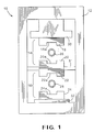
Fig. 1 is a side elevational view of the hydroforming apparatus including a
plurality of separate dies in accordance with this invention, wherein the hydroforming
apparatus is illustrated in a open position prior to the commencement of an operational
cycle of the hydroforming process.
-
Fig. 2 is a side elevational view of the hydroforming apparatus illustrated in
Fig. 1, wherein the hydroforming apparatus is illustrated in a closed position but still
prior to the commencement of the hydroforming process.
-
Fig. 3 is a side elevational view of the hydroforming apparatus illustrated in
Fig. 1, wherein the hydroforming apparatus is illustrated in the closed position after
the commencement of the hydroforming process.
-
Fig. 4 is an enlarged sectional elevational view of a portion of the hydroforming
apparatus taken along line 4-4 of Fig. 3.
-
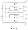
Fig. 5 is a schematic free body diagram of a portion of the hydroforming
apparatus illustrated in Figs. 1 through 4 schematically showing the distribution of
forces that occur during the hydroforming process.
DETAILED DESCRIPTION OF THE PREFERRED EMBODIMENT
-
Referring now to the drawings, there is illustrated in Figs. 1 through 4 an
apparatus, indicated generally at 10, for performing a hydroforming process in
accordance with this invention. The apparatus 10 includes a frame 12 that is sized to
support a plurality of hydroforming dies, two of which are indicated generally at 14
16, in a vertically oriented relationship. Although this invention will be described and
illustrated in the context of the two vertically oriented hydroforming dies 14 and 16, it
will be appreciated that this invention can be practiced with a greater number of such
hydroforming dies if desired. Furthermore, the hydroforming dies 14 and 16 can be
oriented within the hydroforming apparatus 10 in any desired direction other than the
illustrated vertical direction, such as in the horizontal direction for example.
-
The first die 14 includes a first pair of cooperating die sections 18 and 20 that
have respective recesses 18a and 20a formed therein. When the two die sections 18
and 20 are moved together as shown in Figs. 2 and 3, the recesses 18a and 20a formed
therein cooperate to define a first die cavity 21 (see Fig. 2). Similarly, the second die
16 includes a second pair of cooperating die sections 22 and 24 that have respective
recesses 22a and 24a formed therein. When the two die sections 22 and 24 are moved
together as shown in Figs. 2 and 3, the recesses 22a and 24a formed therein cooperate
to define a second die cavity 25 (see Fig. 2).
-
The first die section 18 of the first die 16 is preferably mounted on or otherwise
connected to a first portion of the hydroforming apparatus 10, such as a ram 30, for
movement therewith. The second die section 20 of the first die 14 is preferably
connected to or formed integrally with the first die section 22 of the second die 16.
The combined assembly of the second die section 20 of the first die 14 and the first die
section 22 of the second die 16 is preferably supported on a support mechanism 31 of
the hydroforming apparatus 10 for movement therewith. Alternatively, if the second
die section 20 of the first die 14 and the first die section 22 of the second die 16 are
formed as separate pieces, then each may be supported on individual support
mechanisms (not shown). Lastly, the second die section 24 of the second die 18 is
preferably connected to or formed integrally with a second portion of the
hydroforming apparatus 10, such as a stationary bed 32.
-
Prior to the commencement of an operational cycle of the hydroforming
apparatus 10, the various components thereof are oriented in the opened position
illustrated in Fig. 1. As shown therein, the ram 30 is moved upwardly relative to the
bed 32 so as to position the first die section 18 of the first die 14 in an uppermost
spaced apart position relative to the second die section 24 of the second die 18. At the
same time, the support mechanism 31 is also moved upwardly relative to the bed 32 so
as to position the second die section 20 of the first die 14 and the first die section 22 of
the second die 18 in an intermediate spaced apart position relative to both the first die
section 18 of the first die 14 and the second die section 24 of the second die 18.
-
Thereafter, a first hollow tubular blank 26 is inserted between the spaced apart
die sections 18 and 20 of the first die 16, and a second hollow tubular blank 28 is
inserted between the spaced apart die sections 22 and 24 of the second die 18. The
illustrated tubular blanks 26 and 28 are substantially circular in cross-sectional shape.
However, it should be understood that the invention is not limited to any specific
shape of the tubular blanks 26 and 28, and that the invention can be practiced using
hollow members of any shape, as long as they can be disposed within their respective
die cavities 21 and 25 prior to the hydroforming operation. The tubular blanks 26 and
28 can be manufactured in any conventional manner, such as by rolling a sheet of
metallic material into a complete closed tubular configuration and welding the
adjacent edges together. Alternatively, the tubular blanks 26 and 28 can be
manufactured as seamless tubes. If desired, the tubular blanks 26 and 28 can be
mechanically pre-bent prior to insertion within the first and second dies 16 and 18 so
as to approximate the desired final shapes. It will be appreciated that the two die
cavities 21 and 25 can be configured to form the tubular blanks 26 and 28 into either
the same shape or into two different shapes, as desired.
-
After the tubular blanks 26 and 28 have been inserted into their respective die
cavities 21 and 25, the ram 30 and the support mechanism 31 are moved downwardly
relative to the bed 32 to the closed position illustrated in Fig. 2. During such closing
movement of the first and second dies 16 and 18, portions of the two tubular blanks 26
and 28 may be mechanically deformed somewhat, as is shown in Fig. 2, although such
is not required. When the ram 30 reaches the lowermost position illustrated in Fig. 2,
the dies 14 and 16 are disposed in a stacked relationship between the ram 30 and the
bed 32. As used herein, the term "stacked relationship" means that the cooperating die
sections of each of the dies engage one another, and further that the adjacent die
sections of different dies engage one another. Thus, in the illustrated embodiment, the
first pair of cooperating die sections 18 and 20 of the first die 14 engage one another,
the second pair of cooperating die sections 22 and 24 of the second die 16 engage one
another, and the second die section 20 of the first die 14 engages the first die section
22 of the second die 18. At that time, a conventional clamping mechanism (not
shown) can be engaged so as to maintain the die sections 18 and 20 of the first die 14
and the die sections 22 and 24 of the second die 18 in the illustrated stacked
relationship. Alternatively, if the hydroforming apparatus 10 is adapted from a
conventional mechanical press, the ram 30 can function as the clamping mechanism
by moving it to its bottom dead center position illustrated in Fig. 2 so as to urge or
otherwise maintain the die sections 18 and 20 of the first die 14 and the die sections 22
and 24 of the second die 18 in the illustrated stacked relationship.
-
Then, a first pair of end feed cylinders 35 and 36 are moved laterally into
engagement with the ends of the first tubular blank 26, while a second pair of end feed
cylinders 37 and 38 are moved laterally into engagement with the ends of the second
tubular blank 28, as shown in Fig. 4. The end feed cylinders 35, 36, 37, and 38 have
respective passageways 35a, 36a, 37a, and 38a formed therethrough to facilitate the
filling and emptying of the tubular blanks 26 and 28 with a hydroforming fluid,
typically a relatively incompressible liquid such as water. The illustrated end feed
cylinders 35, 36, 37, and 38 are intended to be representative of any mechanism or
mechanisms for sealing the ends of the tubular blanks 26 and 28, for supplying
pressurized hydroforming fluid into the interiors of the tubular blanks 26 and 28, and
for emptying hydroforming fluid from the interiors of the tubular blanks 26 and 28 at
the conclusion of the hydroforming process.
-
In the next step of the operational cycle of the hydroforming process, the
pressure of the fluid within the tubular blanks 26 and 28 is then increased to such a
magnitude that the tubular blank 26 is expanded outwardly into engagement with the
recesses 18a and 20a formed in the first and second die sections 18 and 20 of the first
die 16, while the second tubular blank 28 is expanded outwardly into engagement with
the recesses 22a and 24a formed in the first and second die sections 22 and 24 of the
second die 18. Such expansion causes the tubular members 26 and 28 to conform with
the shape of the die cavities 21 and 25, respectively, as shown in Figs. 3 and 4.
Preferably, a single source provides pressurized fluid to each of the tubular blanks 26
and 28 at the same time so that the respective hydroforming processes can be
performed substantially simultaneously at the same pressures. As a result, the
hydroforming apparatus 10 is capable of performing two or more hydroforming
operations simultaneously to decrease the overall amount of operational cycle time
and, therefore, increase overall productivity. However, the hydroforming processes
are essentially independent of one another and, therefore, can be performed with
differing parameters, including times, pressures, and the like if desired.
-
Fig. 5 is a free body diagram of a portion of the hydroforming apparatus 10
illustrated in Figs. 1 through 4 schematically showing the distribution of forces that
occur during the hydroforming process. As mentioned above, the introduction of
pressurized fluid within each of the tubular members 26 and 28 causes them to expand
outwardly into engagement with the respective dies 16 and 18. As a result, oppositely
directed forces are exerted by the first tubular blank 26 against the first and second die
sections 18 and 20 of the first die 16, tending to separate move them apart from one
another, thereby disrupting the stacked relationship therebetween. These oppositely
directed separation forces are equal in magnitude to one another and are indicated
graphically at FS1 and FS2 Fig. 5. Similarly, oppositely directed forces are exerted by
the second tubular blank 28 against the first and second die sections 22 and 24 of the
second die 18, tending to separate move them apart from one another, thereby
disrupting the stacked relationship therebetween. These oppositely directed separation
forces are also equal in magnitude to one another and are indicated graphically at FS3
and FS4 in Fig. 5.
-
The frame 12 of the hydroforming apparatus 10 is designed with sufficient
strength to absorb these separation forces FS1 and FS2 to prevent any relative
movement from occurring between the first and second die sections 18 and 20 of the
first die 16 and the first and second die sections 22 and 24 of the second die 18 and
thereby maintain the illustrated stacked relationship. To accomplish this, a first
reaction force FR1 is exerted by the ram 30 of the hydroforming apparatus 10 against
the first die section 18 of the first die 16. The first reaction force FR1 is equal in
magnitude and opposite in direction to the separation force FS1 and, therefore,
prevents any relative movement of the first die section 18 of the first die 16.
Similarly, a second reaction force FR2 is exerted by the bed 32 of the hydroforming
apparatus 10 against the second die section 24 of the second die 18. The second
reaction force FR2 is equal in magnitude and opposite in direction to the separation
force FS4 and, therefore, prevents any relative movement of the second die section 24
of the second die 18.
-
As mentioned above, the hydroforming processes are preferably performed on
the tubular blanks 26 and 28 substantially simultaneously and at substantially the same
internal pressures. In this situation, and assuming that the tubular blanks 26 and 28 are
substantially the same size, then the separation forces FS1 and FS2 generated by the
first tubular blank 26 are substantially equal in magnitude to the separation forces FS3
and FS4 generated by the second tubular blank 28. Thus, the separation forces FS2
and FS3 are substantially equal in magnitude and opposite in direction to one another.
Therefore, such separation forces FS2 and FS3 substantially cancel out one another,
leaving a net force of approximately zero. Thus, for the reasons described above, the
frame 12 of the hydroforming apparatus 10 must only be sufficiently strong as to be
capable of absorbing the summation of the oppositely directed separation forces FS1
and FS4 to maintain the illustrated stacked relationship between the dies 14 and 16.
-
As a result of this cancellation effect, the net force exerted on the frame 12 of
the hydroforming apparatus 10 is equal to the sum of the separation forces FS1 and
FS4. This net force is no greater than would occur if a single die were provided within
the hydroforming apparatus 10. Such a single die would exert separation forces that
would be the same as the separation forces FS1 and FS4. Thus, it can be seen that by
stacking the first and second dies 14 and 16 in the manner described and illustrated
herein, a plurality of tubular blanks 26 and 28 can be hydroformed simultaneously
without increasing the net force exerted on the frame member 12 as compared to a
conventional, single die hydroforming apparatus. Such a structure, therefore, is
capable of performing two or more hydroforming operations simultaneously to
decrease operational cycle time and, therefore, increase overall productivity without
requiring a significant increase in the capacity of the hydroforming apparatus 10.
-
In accordance with the provisions of the patent statutes, the principle and mode
of operation of this invention have been explained and illustrated in its preferred
embodiment. However, it must be understood that this invention may be practiced
otherwise than as specifically explained and illustrated without departing from its
spirit or scope.