EP1103776A2 - Echangeur de chaleur à tubes protégé contre la corrosion et sa méthode de construction - Google Patents
Echangeur de chaleur à tubes protégé contre la corrosion et sa méthode de construction Download PDFInfo
- Publication number
- EP1103776A2 EP1103776A2 EP00660212A EP00660212A EP1103776A2 EP 1103776 A2 EP1103776 A2 EP 1103776A2 EP 00660212 A EP00660212 A EP 00660212A EP 00660212 A EP00660212 A EP 00660212A EP 1103776 A2 EP1103776 A2 EP 1103776A2
- Authority
- EP
- European Patent Office
- Prior art keywords
- pipe
- corrosion
- hole
- construction
- heat exchanger
- Prior art date
- Legal status (The legal status is an assumption and is not a legal conclusion. Google has not performed a legal analysis and makes no representation as to the accuracy of the status listed.)
- Withdrawn
Links
Images

Classifications
-
- F—MECHANICAL ENGINEERING; LIGHTING; HEATING; WEAPONS; BLASTING
- F28—HEAT EXCHANGE IN GENERAL
- F28F—DETAILS OF HEAT-EXCHANGE AND HEAT-TRANSFER APPARATUS, OF GENERAL APPLICATION
- F28F19/00—Preventing the formation of deposits or corrosion, e.g. by using filters or scrapers
- F28F19/002—Preventing the formation of deposits or corrosion, e.g. by using filters or scrapers by using inserts or attachments
Definitions
- the present invention relates to a corrosion-protected construction in a pipe heat exchanger, which construction includes
- Heat exchangers are used particularly in power plants.
- One of the applications of heat exchangers is as a in a power plant used pre-heater for the air, the flue gases formed during production being lead through the pre-heater.
- air is circulated through the pipes of a pipe heat exchanger, and is led to the process after being pre-heated.
- the pipes are usually arranged as banks of pipes, which are connected to each other to form the heat exchanger. In the banks of pipes, the pipes are attached by their ends to a pipe plate, which supports the pipes.
- Corrosion forms a significant problem in terms of the service life of a heat exchanger. Corrosion is generally most rapid in the pipes through which cold air is led to the heat exchanger. Usually, these pipes are also the final pipes in the direction of circulation of the flue gases, when the temperature in the lower part of the pipe heat exchanger is at precisely the condensation point of acid. Thus, especially the sulphur compounds of the flue gas condense onto the surface of the pipes as sulphuric acid, causing the pipes to corrode rapidly. At the same time, the pipes corrode at the attachment welds, when the pipes can even become detached.
- Japanese patent publication number 7253289 discloses precisely an arrangement for attaching surfaced pipes to the pipe plate. According to this publication, special attachment members are used, being placed between the surfaced pipe and the through-hole in the pipe plate, to prevent the surfacing of the pipe from being broken.
- the attachment members themselves are made from corrosion-resistant material. The solution referred to avoids welding, but the installation of the attachment members is difficult and the tightness of the finished attachment is questionable. In addition, the tolerance requirements of the attachment members are disadvantageously tight, in terms of manufacture and installation.
- the present invention is intended to achieve a simpler corrosion-protected construction for a pipe heat exchanger, which is both simpler and more durable than previously.
- the invention is also intended to achieve a method for forming the corrosion-protected construction, which can be used with different kinds of pipes and which is more economical than previously to implement.
- the characteristic features of the construction according to the invention are stated in the accompanying Claim 1, while the characteristic features of the method are stated in the accompanying Claim 7.
- the attachment of the pipe exploits both a corrosion-protection substance and its properties.
- the construction is then corrosion-protected throughout.
- the corrosion protection and also the attachment of the pipe are considerably easier to implement than previously.
- the corrosion-protected construction is entirely tight and will withstand well both thermal and mechanical stress.
- the method according to the invention provides not only corrosion protection, but also easy attachment of the pipe.
- the final result is a corrosion-protected construction, which is durable and has little effect on the flow of the flue gases.
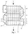
- Figures 1 and 2 show as an embodiment of the invention a air pre-heater, which applies the corrosion-protected construction according to the invention.
- the actual flue gas duct is not shown, but in the pipe heat exchanger of Figure 1 the flue gases travel from the top downwards. The direction of movement of the flue gas is shown with a thick arrow.
- Air travels mostly horizontally in the pipe heat exchanger.
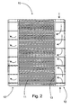
- the pipe heat exchanger is formed of banks of pipes 10, 10', and 10", in which there are numerous pipes a small distance from each other.
- the banks of pipes 10, 10', and 10" are connected to each other by means of air ducts 12, 12', and 12", so that in the embodiment the air travels in an S-shaped route (thin line of dots and dashes).
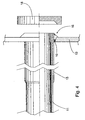
- Figure 3 shows a partial cross-section of one pipe 11, which is being attached to the pipe plate 13, which carries the pipe 11.
- the actual attachment takes place by means of an attachment piece 16 ( Figure 4), made of corrosion-resistant material, arranged between the surfaced pipe 11 and the through-hole 14.
- the attachment piece 16 is made of hardening corrosion protection material, which essentially fills the entire space between the through-hole 14 and the pipe 11.
- hardening means that the corrosion-protection substance can be freely shaped during installation, but dries to harden into an attachment piece.
- Figure 3 shows the construction according to the invention just before the corrosion-protection substance has set.
- the surfacing of the pipe is preferably essentially the same substance as the corrosion-protection substance.
- the corrosion-protection substance is preferably a polymeric composite substance, in which an epoxy resin filler reacts with an aliphatic or cycloaliphatic hardener.
- One such substance is a polymeric composite with the trade name ARC 858.
- the substance is manufactured by A. W. CHESTERTON CO., USA.
- the substance in question can be easily spread, but on hardening forms a joint that withstands various corrosive substances and mechanical and thermal stress.
- the substance with the trade name ARC PYRO S6, made by the same manufacturer, with which the pipes are also surfaced, can also be used for the attachment.
- ARC S4 is also highly suitable for surfacing.
- the clearance is 2 - 10, preferably 4 - 8 mm.
- the corrosion-protection substance is able to fill the entire space between the through-hole and the pipe.
- Penetration can be further improved by forming the through-hole 14 as a conical hole, which is arranged to open out in the direction of the end of the pipe 11 ( Figure 3).
- the coning angle a is 10° - 50°, preferably 20° - 40°, when the thickness layer for the corrosion-protection substance remains reasonable, while the conicality of is, however, sufficient to ensure penetration.
- the surfaced pipe is attached to the pipe plate by means of a hardening corrosion-protection substance, which is used to essentially fill the entire space between the through-hole and the pipe.
- the attachment is then always made absolutely tight in a simple manner. Because corrosion is a problem precisely at the start of the lower pipes, according to the invention, only the pipes of the lower bank of pipes are pre-surfaced.
- the pipes in question are preferably pre-surfaced by spraying a 100 - 1000-mm, preferably 250 - 650-mm length of pipe, beginning from the first end.
- the critical part of the pipe is surfaced, while most of the pipe remains uncoated. Besides achieving sufficient protection, the amount of corrosion-protection substance is reduced.
- the length of the surfacing varies in individual cases, depending on the construction and operating conditions of the heat exchanger.
- the layer thickness 15 is intentionally exaggerated, to illustrate the matter. By spraying, an even layer thickness is achieved and its size can be easily controlled.
- the layer thickness of the surfacing is 0,1 - 2 mm.
- the pipe 11 is set in the through-hole 14 ( Figure 3) and the corrosion-protection substance is extruded into the space 17 (not shown) delimited by the pipe 11 and the through-hole 14.
- the corrosion-protection substance that has been squeezed is extruded in the direction of the pipe 11 and, at the same time, the part that has been pressed is smoothed.
- the amount of corrosion-protection substance is adjusted so that it essentially fills the space between the through-hole and the pipe.
- Figure 4 also shows the pressing tool 18, by means of which the corrosion-protection substance is pressed and smoothed.
- both the corrosion protection of the construction and the attachment of the pipe are ready for use.
- a centring ring 9 Before extrusion, it is preferable to place around the pipe 14 a centring ring 9 according to Figure 3.
- the centring ring 19 is supported on the sides of through-hole 14, thus centring the pipe 11.
- the pipe then needs no other support to remain in the correct place while the corrosion-protection substance is being extruded round it and setting.
- the centring ring also prevents the corrosion-protection substance from being extruded inside the heat exchanger. In addition, this avoids spurting and prevents the corrosion-protection substance from being extruded into only one place.
- the centring ring is preferably made from nylon, so that it will not adhere to the corrosion-protection substance used and can thus be easily removed if necessary, once the corrosion-protection substance has dried.
- the construction according to the invention is highly resistant to corrosive substances, heat, and mechanical stresses. Nevertheless, the construction is economical to manufacture.
- the method according to the invention is simple and can be applied in connection with different kinds of pipes. The method can be implemented, despite minor structural deviations and dimensional errors. The method also permits structures of different materials to be combined and even for an unsurfaced pipe to be attached. Thus, the method according to the invention can be applied to attach all the pipes in a heat exchanger.
Landscapes
- Engineering & Computer Science (AREA)
- Physics & Mathematics (AREA)
- Thermal Sciences (AREA)
- Mechanical Engineering (AREA)
- General Engineering & Computer Science (AREA)
- Heat-Exchange Devices With Radiators And Conduit Assemblies (AREA)
- Protection Of Pipes Against Damage, Friction, And Corrosion (AREA)
Applications Claiming Priority (2)
| Application Number | Priority Date | Filing Date | Title |
|---|---|---|---|
| FI992502 | 1999-11-24 | ||
| FI992502 | 1999-11-24 |
Publications (2)
| Publication Number | Publication Date |
|---|---|
| EP1103776A2 true EP1103776A2 (fr) | 2001-05-30 |
| EP1103776A3 EP1103776A3 (fr) | 2003-08-27 |
Family
ID=8555629
Family Applications (1)
| Application Number | Title | Priority Date | Filing Date |
|---|---|---|---|
| EP00660212A Withdrawn EP1103776A3 (fr) | 1999-11-24 | 2000-11-23 | Echangeur de chaleur à tubes protégé contre la corrosion et sa méthode de construction |
Country Status (1)
| Country | Link |
|---|---|
| EP (1) | EP1103776A3 (fr) |
Cited By (1)
| Publication number | Priority date | Publication date | Assignee | Title |
|---|---|---|---|---|
| DE10331209A1 (de) * | 2003-07-10 | 2005-02-03 | Alto Deutschland Gmbh | Wärmetauscher mit Keramikboden |
Citations (9)
| Publication number | Priority date | Publication date | Assignee | Title |
|---|---|---|---|---|
| FR883606A (fr) * | 1941-04-17 | 1943-07-09 | Kegin Ab | échangeur de chaleur et procédé pour sa fabrication |
| GB731431A (en) * | 1951-03-06 | 1955-06-08 | Ustav Pro Vyzkum Motorovych Vo | A radiator, particularly for internal-combustion engines, and a method of its manufacture |
| GB806195A (en) * | 1955-08-24 | 1958-12-23 | Standard Pressed Steel Co | Improvements in or relating to the hardening of epoxy resins |
| GB855011A (en) * | 1955-12-02 | 1960-11-30 | Welding Engineers | Method of production of plastic material |
| DE1501630A1 (de) * | 1966-07-15 | 1969-10-23 | Hubert Salmen | Roehrenwaermeaustauscher |
| FR2034351A1 (en) * | 1969-03-19 | 1970-12-11 | Chausson Usines Sa | Cooling radiators for vehicles manufac - ture |
| US4295522A (en) * | 1977-08-03 | 1981-10-20 | Willi Frei | Process for the production of a tubular heat exchanger, and a tubular heat exchanger produced according to this process |
| FR2587468A1 (fr) * | 1985-09-16 | 1987-03-20 | Chausson Usines Sa | Procede pour la liaison entre les tubes et les plaques collectrices d'un echangeur de chaleur et echangeur obtenu par ce procede |
| JPH07253289A (ja) * | 1994-03-15 | 1995-10-03 | Hitachi Zosen Corp | 熱交換器における伝熱管の取付け構造および取付け方法 |
-
2000
- 2000-11-23 EP EP00660212A patent/EP1103776A3/fr not_active Withdrawn
Patent Citations (9)
| Publication number | Priority date | Publication date | Assignee | Title |
|---|---|---|---|---|
| FR883606A (fr) * | 1941-04-17 | 1943-07-09 | Kegin Ab | échangeur de chaleur et procédé pour sa fabrication |
| GB731431A (en) * | 1951-03-06 | 1955-06-08 | Ustav Pro Vyzkum Motorovych Vo | A radiator, particularly for internal-combustion engines, and a method of its manufacture |
| GB806195A (en) * | 1955-08-24 | 1958-12-23 | Standard Pressed Steel Co | Improvements in or relating to the hardening of epoxy resins |
| GB855011A (en) * | 1955-12-02 | 1960-11-30 | Welding Engineers | Method of production of plastic material |
| DE1501630A1 (de) * | 1966-07-15 | 1969-10-23 | Hubert Salmen | Roehrenwaermeaustauscher |
| FR2034351A1 (en) * | 1969-03-19 | 1970-12-11 | Chausson Usines Sa | Cooling radiators for vehicles manufac - ture |
| US4295522A (en) * | 1977-08-03 | 1981-10-20 | Willi Frei | Process for the production of a tubular heat exchanger, and a tubular heat exchanger produced according to this process |
| FR2587468A1 (fr) * | 1985-09-16 | 1987-03-20 | Chausson Usines Sa | Procede pour la liaison entre les tubes et les plaques collectrices d'un echangeur de chaleur et echangeur obtenu par ce procede |
| JPH07253289A (ja) * | 1994-03-15 | 1995-10-03 | Hitachi Zosen Corp | 熱交換器における伝熱管の取付け構造および取付け方法 |
Non-Patent Citations (1)
| Title |
|---|
| PATENT ABSTRACTS OF JAPAN vol. 1996, no. 02, 29 February 1996 (1996-02-29) -& JP 07 253289 A (HITACHI ZOSEN CORP), 3 October 1995 (1995-10-03) * |
Cited By (1)
| Publication number | Priority date | Publication date | Assignee | Title |
|---|---|---|---|---|
| DE10331209A1 (de) * | 2003-07-10 | 2005-02-03 | Alto Deutschland Gmbh | Wärmetauscher mit Keramikboden |
Also Published As
| Publication number | Publication date |
|---|---|
| EP1103776A3 (fr) | 2003-08-27 |
Similar Documents
| Publication | Publication Date | Title |
|---|---|---|
| CA1085818A (fr) | Echangeur thermique tubulaire, et procede de fabrication connexe | |
| CA1302394C (fr) | Collecteur d'admission/echappement pour echangeurs de chaleur a panneaux en polymeres thermoplastiques | |
| US5469915A (en) | Panel heat exchanger formed from tubes and sheets | |
| CA2129636C (fr) | Tuyau | |
| US5172877A (en) | Pipe fixing structure using clamp member | |
| US3724537A (en) | Heat exchanger with backed thin tubes | |
| US4474233A (en) | Tube bundle heat exchanger | |
| US6164702A (en) | Reinforced thermoplastic pipe couping | |
| FI86769C (fi) | Saett att tillverka en vaermevaexlare foer anvaendning vid en korrosiv miljoe | |
| EP1103776A2 (fr) | Echangeur de chaleur à tubes protégé contre la corrosion et sa méthode de construction | |
| KR100359531B1 (ko) | 고정형 증발식 열교환기 | |
| US20120192523A1 (en) | Composite structural tie | |
| US5275235A (en) | Panel heat exchanger | |
| JPH02186196A (ja) | 煙道ガス脱硫装置等の腐食防止方法 | |
| EP1627195A1 (fr) | Recipient de traitement pourvu d'elements de refroidissement | |
| JPS5933830B2 (ja) | 熱交換器の製造方法 | |
| EP0954734B1 (fr) | Element de retenue, procede pour revetir un substrat, et installation thermique | |
| KR102663358B1 (ko) | 공조기용 배기배관 연결 구조 | |
| FI73075C (fi) | Isolering och foerfarande foer att isolera en ugnsyta. | |
| CN220170050U (zh) | 一种基于空冷器的耐腐蚀的换热管组 | |
| CA2063718C (fr) | Panneau echangeur de chaleur | |
| JPH05272671A (ja) | 補強された合成樹脂製フランジ付管 | |
| CN214467082U (zh) | 一种埋地管道的保温结构 | |
| SU1032324A1 (ru) | Способ креплени трубы в отверстии сдвоенной трубной доски теплообменника | |
| RU2043885C1 (ru) | Способ изготовления теплообменника |
Legal Events
| Date | Code | Title | Description |
|---|---|---|---|
| PUAI | Public reference made under article 153(3) epc to a published international application that has entered the european phase |
Free format text: ORIGINAL CODE: 0009012 |
|
| AK | Designated contracting states |
Kind code of ref document: A2 Designated state(s): AT BE CH CY DE DK ES FI FR GB GR IE IT LI LU MC NL PT SE TR |
|
| AX | Request for extension of the european patent |
Free format text: AL;LT;LV;MK;RO;SI |
|
| PUAL | Search report despatched |
Free format text: ORIGINAL CODE: 0009013 |
|
| AK | Designated contracting states |
Designated state(s): AT BE CH CY DE DK ES FI FR GB GR IE IT LI LU MC NL PT SE TR |
|
| AX | Request for extension of the european patent |
Extension state: AL LT LV MK RO SI |
|
| AKX | Designation fees paid | ||
| REG | Reference to a national code |
Ref country code: DE Ref legal event code: 8566 |
|
| STAA | Information on the status of an ep patent application or granted ep patent |
Free format text: STATUS: THE APPLICATION IS DEEMED TO BE WITHDRAWN |
|
| 18D | Application deemed to be withdrawn |
Effective date: 20040228 |