EP1103763A1 - Chimney - Google Patents
Chimney Download PDFInfo
- Publication number
- EP1103763A1 EP1103763A1 EP00850196A EP00850196A EP1103763A1 EP 1103763 A1 EP1103763 A1 EP 1103763A1 EP 00850196 A EP00850196 A EP 00850196A EP 00850196 A EP00850196 A EP 00850196A EP 1103763 A1 EP1103763 A1 EP 1103763A1
- Authority
- EP
- European Patent Office
- Prior art keywords
- chimney
- jacket
- insulating material
- flue
- outer jacket
- Prior art date
- Legal status (The legal status is an assumption and is not a legal conclusion. Google has not performed a legal analysis and makes no representation as to the accuracy of the status listed.)
- Granted
Links
Images

Classifications
-
- F—MECHANICAL ENGINEERING; LIGHTING; HEATING; WEAPONS; BLASTING
- F23—COMBUSTION APPARATUS; COMBUSTION PROCESSES
- F23J—REMOVAL OR TREATMENT OF COMBUSTION PRODUCTS OR COMBUSTION RESIDUES; FLUES
- F23J13/00—Fittings for chimneys or flues
- F23J13/02—Linings; Jackets; Casings
- F23J13/025—Linings; Jackets; Casings composed of concentric elements, e.g. double walled
-
- F—MECHANICAL ENGINEERING; LIGHTING; HEATING; WEAPONS; BLASTING
- F23—COMBUSTION APPARATUS; COMBUSTION PROCESSES
- F23J—REMOVAL OR TREATMENT OF COMBUSTION PRODUCTS OR COMBUSTION RESIDUES; FLUES
- F23J11/00—Devices for conducting smoke or fumes, e.g. flues
-
- F—MECHANICAL ENGINEERING; LIGHTING; HEATING; WEAPONS; BLASTING
- F23—COMBUSTION APPARATUS; COMBUSTION PROCESSES
- F23J—REMOVAL OR TREATMENT OF COMBUSTION PRODUCTS OR COMBUSTION RESIDUES; FLUES
- F23J2213/00—Chimneys or flues
- F23J2213/30—Specific materials
- F23J2213/301—Specific materials flexible
-
- F—MECHANICAL ENGINEERING; LIGHTING; HEATING; WEAPONS; BLASTING
- F23—COMBUSTION APPARATUS; COMBUSTION PROCESSES
- F23J—REMOVAL OR TREATMENT OF COMBUSTION PRODUCTS OR COMBUSTION RESIDUES; FLUES
- F23J2213/00—Chimneys or flues
- F23J2213/30—Specific materials
- F23J2213/303—Specific materials metallic
-
- F—MECHANICAL ENGINEERING; LIGHTING; HEATING; WEAPONS; BLASTING
- F23—COMBUSTION APPARATUS; COMBUSTION PROCESSES
- F23J—REMOVAL OR TREATMENT OF COMBUSTION PRODUCTS OR COMBUSTION RESIDUES; FLUES
- F23J2213/00—Chimneys or flues
- F23J2213/40—Heat insulation fittings
Definitions
- the present invention is for a chimney which may be used with one or more fireplaces or hearths both at new installations and rebuilding.
- Chimneys for fireplaces or hearths which are intend to generate heat primarily for heating and hot water generation have traditionally been built of brick.
- the chimney stack then mainly has its extension inside through the building.
- chimneys having chimney flues made from steel Due to the high temperatures of the flue gases these ways of building strictly regulated and at known constructions it is required that the the chimneys or flues are built into special shafts in the building. This takes up a lot of space and means that the building of the chimney must be at the site. Further requirements then are that the shaft must be sealed so that the intrusion of oxygen to possibly leaking out flue gases is prevented as the gases may be explosive.
- Conventional outer jackets made from metal or concrete, pumice or the like has joints and are not satisfactorily sealed.
- the object of the present invention is a chimney which has flue flues made from steel and so made that it may be installed without a shaft.
- a chimney may be installed inside or adjacent all kinds of building constructions and building materials.
- the chimney according to the invention och embodiments thereof has the characterising features which are mentioned in the claims.
- the chimney In order that the chimney may be installed without a shaft the temperature at its outer surface may not at any moment or at any spot be above a highest allowed temperature.
- the chimney according to the present invention thus has a smoke flue which is surrounded by an inner jacket and an outer jacket, preferably made from steel.
- the space between the outer jacket and the smoke flue is filled with insulating material which is of granular or powder form or other form which allows flowing of the material.
- the chimney is so designed that no empty pockets may occur within the insulating material neither at manufacture nor at use.
- the inner jacket is so adapted that its has regular discontinuities through which the insulating material may pass between the two sides of the inner jacket, where the motions of the insulating material may be caused by expansion and retraction of the smoke flue due to the always occurring changes of temperature.
- the smoke flue is made from corrugated steel.
- a reservoir or compensation possibility for insulating material is arranged at the top section of the chimney.
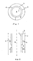
- Figure 1 is a horizontal cross section through a vertical section of a chimney.
- Figure 2 is a vertical cross section through the section of the chimney.
- Figure 3 is a vertical cross section through a partially deflecting chimney.
- the chimney according to the invention comprises a smoke flue 1 which is surrounded by an inner jacket 2 and an outer jacket 3.
- the inner jacket flue 2 is connected to the outer jacket 3 by means of members 4 whereas the smoke flue 1 is freely arranged inside the inner jacket.
- the three tubes are mainly concentric but deviations occur at chimneys having deflections.
- the space between the outer jacket 3 and the smoke flue 1 is totally filled with insulating material.
- the smoke flue 1 is preferably made from corrugated, spirally wound steel which forms a flexible tube. Goods and dimensions are selected considering the application where the selection of fuel and the number of hearths are essential parameters.
- the smoke flue tube is continuous without any discontinuities or junctions except for possible branching where smoke flues from several hearths are joined.
- the outer jacket 3 is divided into sections which are joined by sleeves to a continuous outer jacket.
- the inner jacket 2 is divided into sections. These are fixedly mounted to the outer jacket by means of members 4 so that there is a open slot between each of the inner jacket sections
- Chimneys according to the invention may be made with some sections deflecting from the vertical line for example as shown in figure 3.
- the sections of the outer jacket are connected by sleeves 7 and the section of the inner jacket in a corresponding way by joint guides 8.
- joint guides 8 There are members 4 as required between the outer and inner jacket and that section of the inner jacket which deviates from the vertical line is preferably without joint slots.
- the insulating material 5 is selected so that it will fill up all of the accessible spce between the smoke flue and outer jacket. Thus the material ought to be powdered or granular and be flowing.
- the individual sections of the outer and inner jacket are first joined together where after jacket sections are put together to a chimney jacket.
- the flexible flue is then inserted into the jacket and connected to the hearth in known manner.
- the insulating material is filled in between the flue and the outer jacket by way of pouring into the volume 5 from the top of the chimney.
- the slots between the sections of the inner jacket will then secure that all accessible space is filled with insulating material as this may flow both vertically downwards into accessible volumes and between the sides of the inner jacket by passing through the slots.
- the chimney When in use the chimney is exposed to great variations of temperature which cause expansion and contraction of the flue and the jackets, causing that the insulating material is deformed and very slowly disintegrates into small parts. The disintegration and the movements cause a gradual compacting of the insulating material. Additional insulating material may continuously be added from the storage container and the upwards and downwards movements of the corrugated surface, which are caused by the changes of temperature, provide a feeding function which secures that fresh insulating material is continuously supplied so that no empty pockets occur in the insulation. At the top of the chimney there are means for compensation of the reduced volume of insulating material.
- this comprises a ring of rockwool or the like flexible or elastic insulating material which fills up the entire space between the flue and the outer jacket At the assembly the height of the ring is compressed and it then expands downwards as the volume of the granular insulating material is reduced.
- a container which is in open connection with the insulation volume 5.
- the container which for example may be made as a surrounding funnel or be arranged at one side of the top of the chimney, is filled up with a supply of insulating material which gradually flows down into the insulation space as the existing material there is reduced in volume.
- the container is filled up with insulating material when required.
- the chimney may be installed without a surrounding shaft. It may wholly or partially be prefabricated at a factory, which is preferred in case of new buildings, while by rebuilding and replacement of old chimneys it is also possible to manufacture the jacket as sections of desired length. The are put in position and the flue is then inserted and insulating material is filled in.
- the outer jacket is made as sections which are that much longer than the sections of the inner jacket as corresponds to the size of the desired slots between the sections of the inner jacket. At the assembly it is preferred to make use of joint sleeves with insulating material so that a sealed outer jacket is obtained.
- Chimney according to the invention also brings further advantages with it.
- the low-weight and steady design means that the chimney may be raised on existing framing of joists without reinforcements and the structure is self-supporting also at sidewise deflecting design. Compared to previously known designs also the problem with noise that is generated at the changes of length of the material is reduced. Control and inspection is made easier as the installation is well visible and all joints may be positioned so that they are readily available for inspection.
- the chimney may be adapted to various conditions of use and more than one flue may be installed in one and the same jacket. At change of hearth or method of heating, e. g. changing oil to logs, the flue may be exchanged so that the best condition also are obtained.
- the chimney according to the invention further has the important advantage that there is smaller decrease of the temperature of the flue gas than is the case with hereto known chimney designs for corresponding applications and uses.
- the reduced decrease of the drop of the temperature may be utilised either to to lower the temperature of the output gas from the hearth and so achieve a higher efficiency thereof or to achieve a higher temperature of the flue gases out from the chimney. It is a further advantage that at start up the initially cold chimney quickly reaches a steady state temperature both of the flue and the outer jacket.
- Both the flue and the surrounding jacket may have cross sections which are different from circular, primarily elliptic or rectangular shapes are possible.
- the flue may be a smooth tube.
Landscapes
- Engineering & Computer Science (AREA)
- Mechanical Engineering (AREA)
- General Engineering & Computer Science (AREA)
- Chimneys And Flues (AREA)
- Devices For Conveying Motion By Means Of Endless Flexible Members (AREA)
- Exhaust Silencers (AREA)
Abstract
Description
- The present invention is for a chimney which may be used with one or more fireplaces or hearths both at new installations and rebuilding.
- Chimneys for fireplaces or hearths which are intend to generate heat primarily for heating and hot water generation have traditionally been built of brick. The chimney stack then mainly has its extension inside through the building. There have also been developed chimneys having chimney flues made from steel. Due to the high temperatures of the flue gases these ways of building strictly regulated and at known constructions it is required that the the chimneys or flues are built into special shafts in the building. This takes up a lot of space and means that the building of the chimney must be at the site. Further requirements then are that the shaft must be sealed so that the intrusion of oxygen to possibly leaking out flue gases is prevented as the gases may be explosive. Conventional outer jackets made from metal or concrete, pumice or the like has joints and are not satisfactorily sealed.
- The object of the present invention is a chimney which has flue flues made from steel and so made that it may be installed without a shaft. This means that a chimney may be installed inside or adjacent all kinds of building constructions and building materials. It is also an object that is shall be possible to assemble the chimney in whole in a factory for direct installation at its place in the building. It is further an object to achieve a chimney of low weight so that it may be put on the existing framing of joists without any reinforcement thereof. The chimney according to the invention och embodiments thereof has the characterising features which are mentioned in the claims.
- In order that the chimney may be installed without a shaft the temperature at its outer surface may not at any moment or at any spot be above a highest allowed temperature. The chimney according to the present invention thus has a smoke flue which is surrounded by an inner jacket and an outer jacket, preferably made from steel. The space between the outer jacket and the smoke flue is filled with insulating material which is of granular or powder form or other form which allows flowing of the material. The chimney is so designed that no empty pockets may occur within the insulating material neither at manufacture nor at use. For this aim the inner jacket is so adapted that its has regular discontinuities through which the insulating material may pass between the two sides of the inner jacket, where the motions of the insulating material may be caused by expansion and retraction of the smoke flue due to the always occurring changes of temperature. Preferably the smoke flue is made from corrugated steel. A reservoir or compensation possibility for insulating material is arranged at the top section of the chimney.
- The invention will below be described more in detail with reference to the embodiment which is shown in the enclosed figures.
- Figure 1 is a horizontal cross section through a vertical section of a chimney.
- Figure 2 is a vertical cross section through the section of the chimney.
- Figure 3 is a vertical cross section through a partially deflecting chimney.
- The chimney according to the invention comprises a smoke flue 1 which is surrounded by an
inner jacket 2 and anouter jacket 3. Theinner jacket flue 2 is connected to theouter jacket 3 by means ofmembers 4 whereas the smoke flue 1 is freely arranged inside the inner jacket. The three tubes are mainly concentric but deviations occur at chimneys having deflections. The space between theouter jacket 3 and the smoke flue 1 is totally filled with insulating material. - The smoke flue 1 is preferably made from corrugated, spirally wound steel which forms a flexible tube. Goods and dimensions are selected considering the application where the selection of fuel and the number of hearths are essential parameters. The smoke flue tube is continuous without any discontinuities or junctions except for possible branching where smoke flues from several hearths are joined. The
outer jacket 3 is divided into sections which are joined by sleeves to a continuous outer jacket. Also theinner jacket 2 is divided into sections. These are fixedly mounted to the outer jacket by means ofmembers 4 so that there is a open slot between each of the inner jacket sections - Chimneys according to the invention may be made with some sections deflecting from the vertical line for example as shown in figure 3. The sections of the outer jacket are connected by
sleeves 7 and the section of the inner jacket in a corresponding way byjoint guides 8. There aremembers 4 as required between the outer and inner jacket and that section of the inner jacket which deviates from the vertical line is preferably without joint slots. - The
insulating material 5 is selected so that it will fill up all of the accessible spce between the smoke flue and outer jacket. Thus the material ought to be powdered or granular and be flowing. At manufacture and installation of a chimney according to the invention the individual sections of the outer and inner jacket are first joined together where after jacket sections are put together to a chimney jacket. The flexible flue is then inserted into the jacket and connected to the hearth in known manner. After this the insulating material is filled in between the flue and the outer jacket by way of pouring into thevolume 5 from the top of the chimney. The slots between the sections of the inner jacket will then secure that all accessible space is filled with insulating material as this may flow both vertically downwards into accessible volumes and between the sides of the inner jacket by passing through the slots. - When in use the chimney is exposed to great variations of temperature which cause expansion and contraction of the flue and the jackets, causing that the insulating material is deformed and very slowly disintegrates into small parts. The disintegration and the movements cause a gradual compacting of the insulating material. Additional insulating material may continuously be added from the storage container and the upwards and downwards movements of the corrugated surface, which are caused by the changes of temperature, provide a feeding function which secures that fresh insulating material is continuously supplied so that no empty pockets occur in the insulation. At the top of the chimney there are means for compensation of the reduced volume of insulating material. Primarily this comprises a ring of rockwool or the like flexible or elastic insulating material which fills up the entire space between the flue and the outer jacket At the assembly the height of the ring is compressed and it then expands downwards as the volume of the granular insulating material is reduced. Another alternative is to arrange at the top of the chimney a container which is in open connection with the
insulation volume 5. The container, which for example may be made as a surrounding funnel or be arranged at one side of the top of the chimney, is filled up with a supply of insulating material which gradually flows down into the insulation space as the existing material there is reduced in volume. The container is filled up with insulating material when required. - As it is secured with a chimney according to the invention that there always is sufficient amount of insulating material between the outer jacket and the flue so that the outside temperature of the outer jacket always is below the highest temperature allowed the chimney may be installed without a surrounding shaft. It may wholly or partially be prefabricated at a factory, which is preferred in case of new buildings, while by rebuilding and replacement of old chimneys it is also possible to manufacture the jacket as sections of desired length. The are put in position and the flue is then inserted and insulating material is filled in. Preferably the outer jacket is made as sections which are that much longer than the sections of the inner jacket as corresponds to the size of the desired slots between the sections of the inner jacket. At the assembly it is preferred to make use of joint sleeves with insulating material so that a sealed outer jacket is obtained.
- Chimney according to the invention also brings further advantages with it. The low-weight and steady design means that the chimney may be raised on existing framing of joists without reinforcements and the structure is self-supporting also at sidewise deflecting design. Compared to previously known designs also the problem with noise that is generated at the changes of length of the material is reduced. Control and inspection is made easier as the installation is well visible and all joints may be positioned so that they are readily available for inspection. The chimney may be adapted to various conditions of use and more than one flue may be installed in one and the same jacket. At change of hearth or method of heating, e. g. changing oil to logs, the flue may be exchanged so that the best condition also are obtained.
- The chimney according to the invention further has the important advantage that there is smaller decrease of the temperature of the flue gas than is the case with hereto known chimney designs for corresponding applications and uses. The reduced decrease of the drop of the temperature may be utilised either to to lower the temperature of the output gas from the hearth and so achieve a higher efficiency thereof or to achieve a higher temperature of the flue gases out from the chimney. It is a further advantage that at start up the initially cold chimney quickly reaches a steady state temperature both of the flue and the outer jacket.
- Within the frame of the inventive idea there are also other possible embodiments besides what is apparent from the examples above. Both the flue and the surrounding jacket may have cross sections which are different from circular, primarily elliptic or rectangular shapes are possible. At certain embodiments with a straight chimney or a chimney which only has a small sideways deviation the flue may be a smooth tube.
Claims (5)
- Chimney having a flexible steel tube flue and a surrounding jacket and insulating material between the flue and the jacket characterized in that the jacket comprises an outer jacket (3) and an inner jacket (2) where the outer jacket (3) is continuous along the whole length of the chimney and the inner jacket (2) is split into sections between which there are open slots.
- Chimney according to claim 1 characterized in that the insulating material (5) is in the shape of powder or granules and flowing.
- Chimney according to claim 2 characterized in that the flue (1) is made from a flexible tube of corrugated steel.
- Chimney according to claim 2 or 3 characterized in that means for increasing the volume of insulating material is arranged at the upper section of the chimney in order to compensate for a reduction of the volume of the powdered or granular insulating material.
- Chimney according to claim 4 characterized in that the means comprises a ring or the like flexible or elastic insulating material which fills up the space between the flue and the outer jacket.
Applications Claiming Priority (2)
| Application Number | Priority Date | Filing Date | Title |
|---|---|---|---|
| SE9904246A SE522196C2 (en) | 1999-11-24 | 1999-11-24 | Chimney with flue gas duct of flexible steel pipe and a surrounding jacket and insulating material |
| SE9904246 | 1999-11-24 |
Publications (2)
| Publication Number | Publication Date |
|---|---|
| EP1103763A1 true EP1103763A1 (en) | 2001-05-30 |
| EP1103763B1 EP1103763B1 (en) | 2004-06-16 |
Family
ID=20417832
Family Applications (1)
| Application Number | Title | Priority Date | Filing Date |
|---|---|---|---|
| EP00850196A Expired - Lifetime EP1103763B1 (en) | 1999-11-24 | 2000-11-17 | Chimney |
Country Status (5)
| Country | Link |
|---|---|
| EP (1) | EP1103763B1 (en) |
| AT (1) | ATE269514T1 (en) |
| DE (1) | DE60011552T2 (en) |
| NO (1) | NO316654B1 (en) |
| SE (1) | SE522196C2 (en) |
Citations (6)
| Publication number | Priority date | Publication date | Assignee | Title |
|---|---|---|---|---|
| US2457471A (en) * | 1945-12-05 | 1948-12-28 | Ernest O Howle | Chimney construction |
| US2457470A (en) * | 1945-12-05 | 1948-12-28 | Ernest O Howle | Insulated chimney |
| GB1032469A (en) * | 1963-12-23 | 1966-06-08 | Max Beaumont | Improvements in or relating to insulated chimneys and flues |
| US3464174A (en) * | 1966-11-18 | 1969-09-02 | Rosengrens Plat Ab | Chimneys |
| DE2016520A1 (en) * | 1970-04-02 | 1971-10-21 | Method and device for treating and narrowing chimneys. Anmj Kutter, Gerhard, 1000 Berlin | |
| GB2336893A (en) * | 1998-04-30 | 1999-11-03 | John Trevor Garrod | Flue ducting for atmospheric boilers |
-
1999
- 1999-11-24 SE SE9904246A patent/SE522196C2/en not_active IP Right Cessation
-
2000
- 2000-11-17 AT AT00850196T patent/ATE269514T1/en active
- 2000-11-17 DE DE60011552T patent/DE60011552T2/en not_active Expired - Lifetime
- 2000-11-17 EP EP00850196A patent/EP1103763B1/en not_active Expired - Lifetime
- 2000-11-20 NO NO20005853A patent/NO316654B1/en not_active IP Right Cessation
Patent Citations (6)
| Publication number | Priority date | Publication date | Assignee | Title |
|---|---|---|---|---|
| US2457471A (en) * | 1945-12-05 | 1948-12-28 | Ernest O Howle | Chimney construction |
| US2457470A (en) * | 1945-12-05 | 1948-12-28 | Ernest O Howle | Insulated chimney |
| GB1032469A (en) * | 1963-12-23 | 1966-06-08 | Max Beaumont | Improvements in or relating to insulated chimneys and flues |
| US3464174A (en) * | 1966-11-18 | 1969-09-02 | Rosengrens Plat Ab | Chimneys |
| DE2016520A1 (en) * | 1970-04-02 | 1971-10-21 | Method and device for treating and narrowing chimneys. Anmj Kutter, Gerhard, 1000 Berlin | |
| GB2336893A (en) * | 1998-04-30 | 1999-11-03 | John Trevor Garrod | Flue ducting for atmospheric boilers |
Also Published As
| Publication number | Publication date |
|---|---|
| NO20005853D0 (en) | 2000-11-20 |
| NO20005853L (en) | 2001-05-25 |
| DE60011552T2 (en) | 2005-08-25 |
| SE9904246D0 (en) | 1999-11-24 |
| EP1103763B1 (en) | 2004-06-16 |
| SE9904246L (en) | 2001-05-25 |
| NO316654B1 (en) | 2004-03-22 |
| DE60011552D1 (en) | 2004-07-22 |
| SE522196C2 (en) | 2004-01-20 |
| ATE269514T1 (en) | 2004-07-15 |
Similar Documents
| Publication | Publication Date | Title |
|---|---|---|
| FI124429B (en) | Method and apparatus for supporting the walls of a power boiler | |
| US4979343A (en) | Chimney | |
| US5117770A (en) | Combustion unit | |
| EP1103763B1 (en) | Chimney | |
| JP2010236677A (en) | Fireproof member for piping | |
| US4075799A (en) | Building insulation system and method | |
| US4111107A (en) | Double walled smokestack apparatus | |
| CN212176045U (en) | Laminated floor slab splicing structure and residential system with composite structure | |
| CA1065608A (en) | Blast furnace air heater | |
| CA2498262C (en) | Furnace wall structure | |
| CN2128693Y (en) | Sectional pipe bearing adiabatic supporting seat of boiler bracket roof arch | |
| US865372A (en) | Chimney. | |
| JPH0742411A (en) | Double cylinder type stack and construction method thereof | |
| RU2022024C1 (en) | Blast furnace cooling device | |
| CN220818554U (en) | Kiln top suspension structure | |
| KR200169146Y1 (en) | Elliptic intake/exhaust duct of helical-type | |
| RU2218531C1 (en) | Heat-resistant concrete panel for lining thermal units | |
| CN220451332U (en) | Reinforcing system with chimney lining brick wall as cylinder wall inner template | |
| CN218374516U (en) | Building earthquake-resistant structure | |
| CN215598096U (en) | Z-shaped expansion joint for refractory castable construction | |
| CN219624484U (en) | Ignition furnace lining and ignition furnace | |
| CS197533B1 (en) | Thin-walled chimney for building in in the structure | |
| DE2700246A1 (en) | Two shelled heavily insulated chimney - with load bearing, pressure resistant insulating sheath outside gas pipe | |
| US4947826A (en) | Chimney and fireplace construction | |
| SU1493757A1 (en) | Flue |
Legal Events
| Date | Code | Title | Description |
|---|---|---|---|
| PUAI | Public reference made under article 153(3) epc to a published international application that has entered the european phase |
Free format text: ORIGINAL CODE: 0009012 |
|
| AK | Designated contracting states |
Kind code of ref document: A1 Designated state(s): AT BE CH CY DE DK ES FI FR GB GR IE IT LI LU MC NL PT SE TR |
|
| AX | Request for extension of the european patent |
Free format text: AL;LT;LV;MK;RO;SI |
|
| 17P | Request for examination filed |
Effective date: 20011022 |
|
| AKX | Designation fees paid |
Free format text: AT BE CH CY DE DK ES FI FR GB GR IE IT LI LU MC NL PT SE TR |
|
| GRAH | Despatch of communication of intention to grant a patent |
Free format text: ORIGINAL CODE: EPIDOS IGRA |
|
| GRAS | Grant fee paid |
Free format text: ORIGINAL CODE: EPIDOSNIGR3 |
|
| GRAA | (expected) grant |
Free format text: ORIGINAL CODE: 0009210 |
|
| RAP1 | Party data changed (applicant data changed or rights of an application transferred) |
Owner name: NORDISKA SKORSTENSPRODUKTER AB |
|
| AK | Designated contracting states |
Kind code of ref document: B1 Designated state(s): AT BE CH CY DE DK ES FI FR GB GR IE IT LI LU MC NL PT SE TR |
|
| PG25 | Lapsed in a contracting state [announced via postgrant information from national office to epo] |
Ref country code: IT Free format text: LAPSE BECAUSE OF FAILURE TO SUBMIT A TRANSLATION OF THE DESCRIPTION OR TO PAY THE FEE WITHIN THE PRESCRIBED TIME-LIMIT;WARNING: LAPSES OF ITALIAN PATENTS WITH EFFECTIVE DATE BEFORE 2007 MAY HAVE OCCURRED AT ANY TIME BEFORE 2007. THE CORRECT EFFECTIVE DATE MAY BE DIFFERENT FROM THE ONE RECORDED. Effective date: 20040616 Ref country code: TR Free format text: LAPSE BECAUSE OF FAILURE TO SUBMIT A TRANSLATION OF THE DESCRIPTION OR TO PAY THE FEE WITHIN THE PRESCRIBED TIME-LIMIT Effective date: 20040616 Ref country code: CH Free format text: LAPSE BECAUSE OF FAILURE TO SUBMIT A TRANSLATION OF THE DESCRIPTION OR TO PAY THE FEE WITHIN THE PRESCRIBED TIME-LIMIT Effective date: 20040616 Ref country code: CY Free format text: LAPSE BECAUSE OF FAILURE TO SUBMIT A TRANSLATION OF THE DESCRIPTION OR TO PAY THE FEE WITHIN THE PRESCRIBED TIME-LIMIT Effective date: 20040616 Ref country code: LI Free format text: LAPSE BECAUSE OF FAILURE TO SUBMIT A TRANSLATION OF THE DESCRIPTION OR TO PAY THE FEE WITHIN THE PRESCRIBED TIME-LIMIT Effective date: 20040616 |
|
| REG | Reference to a national code |
Ref country code: GB Ref legal event code: FG4D |
|
| REG | Reference to a national code |
Ref country code: CH Ref legal event code: EP |
|
| REF | Corresponds to: |
Ref document number: 60011552 Country of ref document: DE Date of ref document: 20040722 Kind code of ref document: P |
|
| REG | Reference to a national code |
Ref country code: IE Ref legal event code: FG4D |
|
| PG25 | Lapsed in a contracting state [announced via postgrant information from national office to epo] |
Ref country code: DK Free format text: LAPSE BECAUSE OF FAILURE TO SUBMIT A TRANSLATION OF THE DESCRIPTION OR TO PAY THE FEE WITHIN THE PRESCRIBED TIME-LIMIT Effective date: 20040916 Ref country code: GR Free format text: LAPSE BECAUSE OF FAILURE TO SUBMIT A TRANSLATION OF THE DESCRIPTION OR TO PAY THE FEE WITHIN THE PRESCRIBED TIME-LIMIT Effective date: 20040916 Ref country code: SE Free format text: LAPSE BECAUSE OF FAILURE TO SUBMIT A TRANSLATION OF THE DESCRIPTION OR TO PAY THE FEE WITHIN THE PRESCRIBED TIME-LIMIT Effective date: 20040916 |
|
| PG25 | Lapsed in a contracting state [announced via postgrant information from national office to epo] |
Ref country code: ES Free format text: LAPSE BECAUSE OF FAILURE TO SUBMIT A TRANSLATION OF THE DESCRIPTION OR TO PAY THE FEE WITHIN THE PRESCRIBED TIME-LIMIT Effective date: 20040927 |
|
| PG25 | Lapsed in a contracting state [announced via postgrant information from national office to epo] |
Ref country code: IE Free format text: LAPSE BECAUSE OF NON-PAYMENT OF DUE FEES Effective date: 20041117 Ref country code: LU Free format text: LAPSE BECAUSE OF NON-PAYMENT OF DUE FEES Effective date: 20041117 |
|
| PG25 | Lapsed in a contracting state [announced via postgrant information from national office to epo] |
Ref country code: MC Free format text: LAPSE BECAUSE OF NON-PAYMENT OF DUE FEES Effective date: 20041130 |
|
| REG | Reference to a national code |
Ref country code: CH Ref legal event code: PL |
|
| ET | Fr: translation filed | ||
| PLBE | No opposition filed within time limit |
Free format text: ORIGINAL CODE: 0009261 |
|
| STAA | Information on the status of an ep patent application or granted ep patent |
Free format text: STATUS: NO OPPOSITION FILED WITHIN TIME LIMIT |
|
| 26N | No opposition filed |
Effective date: 20050317 |
|
| REG | Reference to a national code |
Ref country code: IE Ref legal event code: MM4A |
|
| PG25 | Lapsed in a contracting state [announced via postgrant information from national office to epo] |
Ref country code: PT Free format text: LAPSE BECAUSE OF NON-PAYMENT OF DUE FEES Effective date: 20041116 |
|
| REG | Reference to a national code |
Ref country code: FR Ref legal event code: PLFP Year of fee payment: 16 |
|
| REG | Reference to a national code |
Ref country code: FR Ref legal event code: PLFP Year of fee payment: 17 |
|
| REG | Reference to a national code |
Ref country code: FR Ref legal event code: PLFP Year of fee payment: 18 |
|
| REG | Reference to a national code |
Ref country code: FR Ref legal event code: PLFP Year of fee payment: 19 |
|
| PGFP | Annual fee paid to national office [announced via postgrant information from national office to epo] |
Ref country code: NL Payment date: 20191119 Year of fee payment: 20 Ref country code: FI Payment date: 20191016 Year of fee payment: 20 Ref country code: DE Payment date: 20191017 Year of fee payment: 20 |
|
| PGFP | Annual fee paid to national office [announced via postgrant information from national office to epo] |
Ref country code: FR Payment date: 20191017 Year of fee payment: 20 Ref country code: BE Payment date: 20191015 Year of fee payment: 20 |
|
| PGFP | Annual fee paid to national office [announced via postgrant information from national office to epo] |
Ref country code: AT Payment date: 20191016 Year of fee payment: 20 |
|
| PGFP | Annual fee paid to national office [announced via postgrant information from national office to epo] |
Ref country code: GB Payment date: 20191017 Year of fee payment: 20 |
|
| REG | Reference to a national code |
Ref country code: DE Ref legal event code: R071 Ref document number: 60011552 Country of ref document: DE |
|
| REG | Reference to a national code |
Ref country code: NL Ref legal event code: MK Effective date: 20201116 |
|
| REG | Reference to a national code |
Ref country code: GB Ref legal event code: PE20 Expiry date: 20201116 |
|
| REG | Reference to a national code |
Ref country code: FI Ref legal event code: MAE |
|
| REG | Reference to a national code |
Ref country code: AT Ref legal event code: MK07 Ref document number: 269514 Country of ref document: AT Kind code of ref document: T Effective date: 20201117 Ref country code: BE Ref legal event code: MK Effective date: 20201117 |
|
| PG25 | Lapsed in a contracting state [announced via postgrant information from national office to epo] |
Ref country code: GB Free format text: LAPSE BECAUSE OF EXPIRATION OF PROTECTION Effective date: 20201116 |